Jung DS 4092 TS Operator's manual

Product documentation
Rotary sensor
Art. No. DS 4092 TS
ALBRECHT JUNG GMBH & CO. KG
Volmestraße 1
58579 Schalksmühle
Telefon: +49.23 55.8 06-0
Telefax: +49.23 55.8 06-2 04
www.jung.de
Service Center
Kupferstr. 17-19
44532 Lünen
Germany
Issue: 02.04.2014
TD 6505x320 V2

Art. No. DS 4092 TS
Contents
Product definition1 4.................................................................................................................
Product catalogue1.1 4...........................................................................................................
Function1.2 4..........................................................................................................................
Accessories1.3
Installation, electrical connection and operation2 5..............................................................
Safety instructions2.1 5...........................................................................................................
Device components2.2 6........................................................................................................
Fitting and electrical connection2.3 7......................................................................................
Commissioning2.4 9...............................................................................................................
Operation2.5 10......................................................................................................................
Technical data3 11....................................................................................................................
Software description4 12..........................................................................................................
Software specification4.1 12...................................................................................................
Software "Rotary sensor with extensions 10FE1x"4.2 13.......................................................
Scope of functions4.2.1 13.................................................................................................
Notes on software4.2.2 15..................................................................................................
Object table4.2.3 16...........................................................................................................
Objects push-button4.2.3.1 16.......................................................................................
Objects rotary knob4.2.3.2 20........................................................................................
Objects disabling functions push-button rotary knob4.2.3.3 23.....................................
Objects Buzzer4.2.3.4 30...............................................................................................
Objects Status-LED4.2.3.5 32........................................................................................
Object energy saving mode4.2.3.6 33...........................................................................
Extension input objects4.2.3.7 34..................................................................................
Functional description4.2.4 37............................................................................................
Push-button (PB)4.2.4.1 37............................................................................................
Push-button function Switching4.2.4.1.1 37..............................................................
Push-button function Dimming4.2.4.1.2 38...............................................................
Push-button function Venetian blind4.2.4.1.3 39.......................................................
Push-button function value transmitter4.2.4.1.4 42...................................................
Push-button function Scene extension4.2.4.1.5 44...................................................
Push-button function 2-channel operation4.2.4.1.6 45..............................................
Rotary knob (RK)4.2.4.2 47...........................................................................................
Rotary knob function Switching4.2.4.2.1 47..............................................................
Rotary knob function Dimming4.2.4.2.2 49...............................................................
Rotary knob function Venetian blind4.2.4.2.3 56.......................................................
Rotary knob function 1-byte value transmitter4.2.4.2.4 58........................................
Rotary knob function 2-byte value transmitter4.2.4.2.5 66........................................
Rotary knob function scene extension4.2.4.2.6 72....................................................
Disabling function for push-button and rotary knob4.2.4.3 74.......................................
Extension inputs (E1, E2, E3)4.2.4.4 78........................................................................
Extension function Switching4.2.4.4.1 78..................................................................
Extension function Dimming4.2.4.4.2 79...................................................................
Extension function Venetian blind4.2.4.4.3 80..........................................................
Extension function Value transmitter / Scene extension4.2.4.4.4 82........................
Product documentation
Page 2 of 143

Art. No. DS 4092 TS
Disabling function for extension inputs4.2.4.4.5 85...................................................
Acoustic signal encoder4.2.4.5 86.................................................................................
Status-LED (only with application program of version 1.2)4.2.4.6 90............................
Energy saving mode4.2.4.7 92......................................................................................
Delivery state4.2.4.8 94.................................................................................................
Parameters4.2.5 95............................................................................................................
Parameter push-button / rotary knob4.2.5.1 95.............................................................
Extension inputs parameter4.2.5.2 126.........................................................................
Energy saving mode parameter4.2.5.3 140...................................................................
Appendix5 142...........................................................................................................................
Index5.1 142...........................................................................................................................
Product documentation
Page 3 of 143

Art. No. DS 4092 TS
1 Product definition
1.1 Product catalogue
Product name: Rotary sensor
Use: Sensor
Design: FM (flush-mounted)
Art. No. DS 4092 TS
1.2 Function
The KNX rotary sensor combines the functions of a push-button sensor with extension
connection and a bus coupling unit in a single device. The KNX rotary sensor follows the
familiar operation concept of a press/rotary dimmer with incremental encoder. The rotary knob
serves as a rocker function (turn to the left <-> turn to the right, e.g. dimming), the push-button
serves as a push-button function (e.g. switching).
The KNX rotary sensor can be combined with the covers of conventional rotary dimmers in
which KNX operating functions can be integrated conventionally into electrical installations.
The function of the rotary knob in the ETS alternative can be configured to the following
functions: switching, dimming, Venetian blind, 1 byte value transmitter, 2-byte value transmitter,
scene extension. Depending on the direction of rotation, the commands of the functions (ON,
OFF / brighter, darker / UP, DOWN...) are transmitted to the bus via the communication objects
assigned to the rotary knob.
The push-button can be configured to the following functions: switching, dimming, Venetian
blind, 1 byte value transmitter, 2-byte value transmitter, scene extension, 2-channel operation.
The function of the rotary knob can be combined with the function of the push-button or can be
operated independently of it, too.
The KNX rotary sensor additionally has three extension inputs that affect the KNX separately
from the push-button and rotary knob. The connected potential-free switch or button contacts
are downloaded to the device via a shared reference potential. The inputs can transmit
telegrams independent of each other for switching or dimming, for shutter control or transmitter
application (dimmer value transmitter, light scene extension).
The connection of 230 V signals or other external voltages to the extension inputs is not
permitted!
The device has an acoustic buzzer (Piezo signal transmitter) that can be used for
acknowledgement or status signalling. Additionally, the integrated buzzer can signal a warning
or ring tone, an alarm and an active programming mode. The volume of the buzzer can be
differentiated in two states by means of a 1-bit communication object. The buzzer volume for
alarm signalling can also be configured separately.
In addition, the device has two red Status LEDs. These Status LEDs can - only when Version
1.2 of the application is used - be switched on or off independently of one another, function as a
button-press display or as a status display (control via separate communication object), as
required. When functioning as a button-press display, the left LED displays operations of the
push-button, whilst the right LED displays operations of the rotary knob.
The use of both Status LEDs is optional. If the visual display functions are required, then special
design covers with a control window must be used (see accessories).
The device has an energy saving mode to save electrical energy during operation. If the
function is used, the device switches to the energy saving mode after a preset time without
operation or controlled by an external telegram to a separate object. In the energy saving mode,
essential operation and signalling functions of the device are switched off. The acoustic signal
transmitter and extension inputs are then without any functions. The energy saving mode can
be deactivated by operating the rotary knob or push-button or by a special telegram. Afterwards,
the device is fully functional again.
A bus coupling unit is already permanently integrated in the KNX rotary sensor, allowing the
device to be connected directly to the bus line during commissioning. It requires no additional
power supply for operation. For project design and commissioning of the device, ETS3.0 from
Version "d" onwards, ETS4 from version 4.0.7 onwards or ETS5 is required.
Page 4 of 143
Product definition
Art. No. DS 4092 TS
2 Installation, electrical connection and operation
2.1 Safety instructions
Electrical equipment may only be installed and fitted by electrically skilled persons. The
applicable accident prevention regulations must be observed.
Failure to observe the instructions may cause damage to the device and result in fire and
other hazards.
Make sure during the installation that there is always sufficient insulation between the
mains voltage and the bus. A minimum distance of at least 4 mm must be maintained
between bus conductors and mains voltage cores.
Do not connect any external voltage to the inputs, since doing so may damage the
device(s), and the SELV potential on the KNX bus line will no longer be available.
The device may not be opened or operated outside the technical specifications.
Page 5 of 143
Installation, electrical connection and operation

Art. No. DS 4092 TS
2.2 Device components
Figure 1: Device components (View of front side)
(1) Status LED (red)
(2) Programming button
(3) Slide-in shaft for rotary knob with push-button (incremental encoder)
(4) Terminals for extension inputs
(5) KNX bus connection
Page 6 of 143
Installation, electrical connection and operation

Art. No. DS 4092 TS
2.3 Fitting and electrical connection
Connecting and fitting the device
DANGER!
Electrical shock on contact with live parts in the installation environment.
Electrical shocks can be fatal.
Before working on the device, disconnect the power supply and cover up live
parts in the working environment.
The device is installed in a standard flush-mounted appliance box or in suitable flush-mounted
switch boxes. Potential-free contacts (e.g. installation switches or buttons, magnetic contacts)
can be connected optionally as required.
iThe KNX rotary sensor can be installed in various Jung flush-mounted product ranges
(series AS, A, CD, LS). For this reason, the frames and covers are design-specific. The
design elements must be ordered separately (see accessories).
iIdeally, the device should be installed in such a way that the Status LEDs are at the top.
Figure 2: Mounting of the rotary sensor with decorative cover
(3) Slide-in shaft for rotary knob with push-button (incremental encoder)
(4) Terminals for extension inputs
(5) KNX bus connection
(6) Device with supporting plate
(7) Design frame (accessories)
(8a) Design central plate (accessories)
(8b) Design central plate with light guide for Status LED (accessories)
(9) Design control button (accessories)
oConnect KNX bus line with terminal to bus connection (5).
oOptionally, connect potential-free contacts to the extension inputs (4) (figure 3).
Page 7 of 143
Installation, electrical connection and operation

Art. No. DS 4092 TS
Figure 3: Connection of potential-free contacts to the extension inputs
oInstall the device with supporting plate (6) in a flush-mounted appliance box.
iBefore installing the decorative covers, program the physical address.
oMount the design frame (7), the central plate (8) and the control button (9).
Page 8 of 143
Installation, electrical connection and operation

Art. No. DS 4092 TS
2.4 Commissioning
Programming the physical address
The commissioning of the device is basically confined to programming of the physical address
and the application program with the ETS.
Project design and commissioning of the device using ETS3.0 from Version "d" onwards, ETS4
from version 4.0.7 onwards or ETS5.
The device is connected and ready for operation.
An appropriate device must be created and configured in the ETS project.
oDismantle central plate(7) and control button (8) if the device has already been completely
mounted (figure 2).
oActivating Programming mode: press the programming button (2).
The device indicates the programming mode with a pulsating tone (0.5 Hz) at maximum
volume.
oProgram the physical address with the help of the ETS.
Signal tone becomes silent.
Programming the application program
After programming the physical address, the application must be loaded into the device. The
ETS detects automatically whether a valid application has already been programmed into the
device before. To reduce the programming time, the ETS downloads the whole application only
if the device was programmed beforehand with another application or with no application at all.
In all other cases, the ETS makes a time-optimised partial download in which only the modified
data is loaded into the device.
Page 9 of 143
Installation, electrical connection and operation

Art. No. DS 4092 TS
2.5 Operation
The KNX rotary sensor combines the functions of a push-button sensor with extension
connection and a bus coupling unit in a single device. The KNX rotary sensor follows the
familiar operation concept of a press/rotary dimmer with incremental encoder. The rotary knob
serves as a rocker function (turn to the left <-> turn to the right, e.g. dimming), the push-button
serves as a push-button function (e.g. switching).
The KNX rotary sensor can be installed in various Jung flush-mounted product ranges (series
AS, A, CD, LS). For this reason, the frames and covers are design-specific. The design
elements must be ordered separately (see accessories).
The function of the rotary knob is defined in the ETS. The rotary knob can be set to the following
functions: switching, dimming, Venetian blind, 1-byte value transmitter, 2-byte value transmitter,
scene extension. Depending on the direction of rotation, the commands of the functions (ON,
OFF / brighter, darker / UP, DOWN...) are transmitted to the bus via the communication objects
assigned to the rotary knob.
The push-button is configured in the ETS independently of the rotary knob and can therefore
perform different functions, too. It is possible to combine the function of the rotary knob with the
function of the push-button via the communication objects (e.g. control of an actuator: turning =
dimming a lighting system / pressing = switching a lighting system). Alternatively, rotary knob
and push-button can also be operated independently (e.g. control of separate actuators: turning
= Venetian blind control / pressing = switching a lighting system).
The push-button can be configured to the following functions in the ETS: switching, dimming,
Venetian blind, 1 byte value transmitter, 2-byte value transmitter, scene extension, 2-channel
operation.
The KNX rotary sensor additionally has three extension inputs that affect the KNX separately
from the push-button and rotary knob. The connected potential-free switch or button contacts
are downloaded to the device via a shared reference potential. The inputs can transmit
telegrams independent of each other for switching or dimming, for shutter control or transmitter
application (dimmer value transmitter, light scene extension).
Page 10 of 143
Installation, electrical connection and operation

Art. No. DS 4092 TS
3 Technical data
General
Protection class III
Mark of approval KNX
Ambient temperature -25 ... +55 °C
Storage/transport temperature -25 ... +55 °C
Relative humidity 5 ... 93 % (No moisture condensation)
KNX supply
KNX medium TP 1
Commissioning mode S-mode
Rated voltage KNX DC 21 ... 32 V SELV
Current consumption KNX max. 12.5 mA
Connection type for bus Connection terminal
Extension inputs
Poll voltage, extension inputs approx. 20 V
Cable length max. 5 m
Page 11 of 143
Technical data

Art. No. DS 4092 TS
4 Software description
4.1 Software specification
ETS search paths: Push-button / Rotary sensor / Rotary sensor
Configuration: S-mode standard
AST type: "00"Hex / "0" Dec
PEI connector: no connector
Application program:
No. Short description Name Version from mask
version
1 Multifunctional application program
(rotary knob and push-button) incl.
extension function and control of an
acoustic signal transmitter.
Rotary sensor with
extensions 10FE11
1.1
for ETS3.0
Version d,
ETS4 and
ETS5.
705
2 Multifunctional application program
(rotary knob and push-button) incl.
extension function and control of an
acoustic signal transmitter and two
Status LEDs.
This application program replaces
Version 1.1.
Rotary sensor with
extensions 10FE12
1.2
for ETS3.0
Version d,
ETS4 and
ETS5.
705
Page 12 of 143
Software specification

Art. No. DS 4092 TS
4.2 Software "Rotary sensor with extensions 10FE1x"
4.2.1 Scope of functions
General
- 1 x rotary knob (RK), 1 x push-button (PB), 3 x extension inputs for potential-free contacts.
- Shared disable object for rotary knob and push-button. Different disabling reactions
configurable.
- Delay after bus voltage return, debounce time and telegram rate limit can be configured for
the extension inputs.
- Acoustic buzzer (Piezo signal transmitter) for acknowledgement or status signalling or for
signalling a warning, ring tone or alarm tone. The volume of the buzzer can be set.
- Two red Status LEDs can - only when Version 1.2 of the application is used - be switched
on or off permanently independently of one another, function as a button-press display or
as a status display (activation via separate communication object), as required. When
functioning as a button-press display, the left LED displays operations of the push-button,
whilst the right LED displays operations of the rotary knob.
- Energy saving mode for saving electrical energy. The device can switch to the energy
saving mode without operation after a preset time or controlled by an external telegram. In
the energy saving mode, essential operation and signalling functions of the device are
switched off. The acoustic signal transmitter and extension inputs are then without any
functions.
Push-button (PB)
- Free allocation of the functions switching, dimming, Venetian blind, 1-byte value
transmitter, 2-byte value transmitter, scene extension, 2-channel operation.
- Scope of detail for the "Switching" function:
Command on pressing and releasing the button is independently adjustable (ON, OFF,
TOGGLE, no reaction).
- Scope of detail for the "Dimming" function:
Command on pressing the button is adjustable (no reaction, lighter - ON, darker - OFF,
lighter/darker - TOGGLE, lighter - TOGGLE, darker - TOGGLE). Time between dimming
and switching and dimming step width is adjustable. Telegram repetition and stop telegram
transmission possible.
- Scope of detail for the "Venetian blind" function:
Command on pressing the button is adjustable (no reaction, UP, DOWN, TOGGLE).
Operation concept configurable. Time adjustable between short-time and long-time
operation (only for short – long – short) Adjustable slat adjustment time (time during which
a long time command can be terminated by releasing the push-button).
- Scope of detail for the "1-byte value transmitter" and "2-byte value transmitter" functions:
1-byte: Choice of value range (0...100 %, 0...255) / 2-byte: function configurable
(temperature value transmitter, brightness value transmitter, transmitter 0...65535)
On a long button-press, value adjustment with different step widths and optional overflow
when the end of the value range is reached.
- Scope of detail for the "Scene extension" function:
Recall of one from up to 64 external scenes via the extension object of the button.
Optionally with storage function on a long button-press.
- Scope of detail for the "2-channel operation" function:
Operation of up to two independent channels. This means that only one button-press is
enough to transmit up to two telegrams to the bus. The channels can be configured
independently of one another for the Switching, Value transmitter (1 byte) or Temperature
value transmitter (2 bytes) functions.
Rotary knob (RK)
- Free allocation of the functions switching, dimming, Venetian blind, 1-byte value
transmitter, 2-byte value transmitter, scene extension.
Page 13 of 143
Software "Rotary sensor with extensions 10FE1x"
Scope of functions

Art. No. DS 4092 TS
- Scope of detail for the "Switching" function:
Command on turning clockwise and anticlockwise is separately adjustable (ON, OFF,
TOGGLE, no reaction). Optionally, separate objects for both directions of rotation (e.g. for
controlling different actuation channels).
- Scope of detail for the "Dimming" function:
Operation concept is adjustable (dimming with or without OFF telegram / dimming comfort:
Operation dependent on speed and rotation angle). Command on turning is configurable
depending on the direction of rotation (brighter - ON, darker - OFF). Dimming step width in
the operation concept "Dimming comfort" is adjustable.
- Scope of detail for the "Venetian blind" function:
Operation concept: Move - Step. Command on turning is adjustable depending on the
direction of rotation (UP, DOWN). Rotation angle for slat adjustment is definable.
- Scope of detail for the "1-byte value transmitter" and "2-byte value transmitter" functions:
1-byte: Choice of function (0...100 %, 0...255, value transmitter comfort
0...255: speed dependent operation for value adjustment) / 2-byte: function configurable
(temperature value transmitter, brightness value transmitter, transmitter 0...65535)
Value adjustment with different step widths, direction of the value adjustment and optional
overflow when the end of the value range is reached.
- Scope of detail for the "Scene extension" function:
Recall of one from up to 64 external scenes via the extension object of the rotary knob.
Different scenes can be recalled depending on the direction of rotation. Without memory
function.
- Time definition for standstill of the rotary knob for detecting a new operation.
Extension inputs (E1, E2, E3)
- Free allocation of the functions switching, dimming, Venetian blind and value transmitter.
- Behaviour on bus voltage return can be configured separately for each input.
- Scope of detail for the "Switching" function:
Two independent switching objects available for each input (switching commands can be
configured individually).
Command can be set independently for rising and falling edge (ON, OFF, TOGGLE, no
reaction).
Independent cyclical transmission of the switching objects can be selected depending on
the edge or depending on the object value.
- Scope of detail for the "Dimming" function:
Single-surface and double-surface operation possible.
Time between dimming and switching and dimming step width is adjustable.
Telegram repetition and stop telegram transmission possible.
- Scope of detail for the "Venetian blind" function:
Command can be set independently for rising edge (no function, UP, DOWN, TOGGLE).
Operation concept configurable (short – long – short or long – short).
Time adjustable between short-time and long-time operation (only for short – long – short)
Adjustable slat adjustment time (time during which a MOVE command can be terminated
by releasing a pushbutton on the input).
- Scope of detail for the "Value transmitter" function:
Edge (pushbutton as NO contact, pushbutton as NC contact, switch) and value for edge
can be configured.
Value adjustment for pushbutton long key-press possible for value transmitter.
For light scene extension with memory function, the scene can also be saved without prior
recall.
- Disable object for disabling individual inputs (polarity of the disable object is adjustable).
Page 14 of 143
Software "Rotary sensor with extensions 10FE1x"
Scope of functions

Art. No. DS 4092 TS
4.2.2 Notes on software
ETS project design and commissioning
For project design and commissioning of the device, ETS3.0 from Version "d" onwards, ETS4
from version 4.0.7 onwards or ETS5 is required. The product database is offered in the
*.VD4 format. No product database is available for ETS2 and older versions of ETS3.
Unloading of the application program
If the application program is unloaded by the ETS, the Status LEDs flash at a slow rate in an
alternating pattern (approx. 0.75 Hz). In this case, the device no longer reacts to operations nor
does it execute signalling functions anymore. The delivery state (see page 94) described
cannot be restored by unloading with the ETS.
Page 15 of 143
Software "Rotary sensor with extensions 10FE1x"
Notes on software

Art. No. DS 4092 TS
4.2.3 Object table
Number of communication objects: 30
(max. object number 29)
Number of addresses (max): 254
Number of assignments (max): 255
Maximum table length 255
4.2.3.1 Objects push-button
Function: Switching
Object
h0
Function
Switching
Name
Push-button -
Output
Type
1-bit
DPT
1.xxx
Flag
C, W, T,
(R) 1
Description 1-bit object for transmission of switching telegrams (ON, OFF).
Function: Dimming
Object
h0
Function
Switching
Name
Push-button -
Output
Type
1-bit
DPT
1.xxx
Flag
C, W, T,
(R) 1
Description 1-bit object for transmission of switching telegrams (ON, OFF).
Function: Dimming
Object
h1
Function
Dimming
Name
Push-button -
Output
Type
4-bit
DPT
3.007
Flag
C, W, T,
(R) 1
Description 4-bit object for the transmission of relative dimming telegrams.
Function: Venetian blind
Object
h0
Function
Short time operation
Name
Push-button -
Output
Type
1-bit
DPT
1.007
Flag
C, -, T, (R)
1
Description 1-bit object for the transmission of telegrams with which a Venetian blind or
shutter drive motor can be stopped or with which the blind slats can be
adjusted by short time operation.
1: For reading, the R-flag must be set. The last value written to the object via the bus or by the
device will be read.
Page 16 of 143
Software "Rotary sensor with extensions 10FE1x"
Object table

Art. No. DS 4092 TS
Function: Venetian blind
Object
h1
Function
Long-time operation
Name
Push-button -
Output
Type
1-bit
DPT
1.008
Flag
C, W, T,
(R) 1
Description 1-bit object for the transmission of telegrams with which a Venetian blind or
shutter drive motor can be can be moved upwards or downwards.
Function: 1-byte value transmitter
Object
h0
Function
Value
Name
Push-button -
Output
Type
1 byte
DPT
5.xxx
Flag
C, W, T,
(R) 1
Description 1-byte object for the transmission of values from 0 to 255 (corresponding to
values from 0 % to 100 %). If the adjustment of the value is enabled, the
object can transmit telegrams cyclically after a long press through which the
value can be reduced or increased by a set step width.
Function: 2-byte value transmitter
Object
h0
Function
Value
Name
Push-button -
Output
Type
2 byte
DPT
7.xxx
Flag
C, W, T,
(R) 1
Description 2-byte object for the transmission of values from 0 to 65535. If the adjustment
of the value is enabled, the object can transmit telegrams cyclically after a
long press through which the value can be reduced or increased by a
presettable step width.
Function: 2-byte value transmitter
Object
h0
Function
Temperature value
Name
Push-button -
Output
Type
2 byte
DPT
9.001
Flag
C, W, T,
(R) 1
Description 2 -byte object for the transmission of a temperature value from 0 °C to 40 °C.
If the adjustment of the value is enabled, the object can transmit telegrams
cyclically after a long press with which the value can be reduced or increased
by 1 K.
Function: 2-byte value transmitter
Object
h0
Function
Brightness value
Name
Push-button -
Output
Type
2 byte
DPT
9.004
Flag
C, W, T,
(R) 1
Description 2-byte object for the transmission of a brightness level value from 0 to 1500
lux. If the adjustment of the value is enabled, the object can transmit cyclical
telegrams after a long press with which the value can be reduced or increased
by 50 lux.
1: For reading, the R-flag must be set. The last value written to the object via the bus or by the
device will be read.
Page 17 of 143
Software "Rotary sensor with extensions 10FE1x"
Object table

Art. No. DS 4092 TS
Function: Scene extension
Object
h0
Function
Scene extension
Name
Push-button -
Output
Type
1 byte
DPT
18.001
Flag
C, -, T, (R)
1
Description 1-byte object for recalling or for storing one of 64 scenes max. from a scene
push button sensor.
Function: 2-channel operation
Object
h0
Function
Channel 1 switching
Name
Push-button -
Output
Type
1-bit
DPT
1.xxx
Flag
C, W, T,
(R) 1
Description 1-bit object for the transmission of switching telegrams, if 2-channel operation
is activated.
Function: 2-channel operation
Object
h0
Function
Channel 1 value
Name
Push-button -
Output
Type
1 byte
DPT
5.xxx
Flag
C, -, T, (R)
1
Description 1-byte object for the transmission of value telegrams, if 2-channel operation is
activated.
Function: 2-channel operation
Object
h0
Function
Channel 1 temperature value
Name
Push-button -
Output
Type
2 byte
DPT
9.001
Flag
C, -, T, (R)
1
Description 2-byte object for the transmission of temperature value telegrams if 2-channel
operation is activated.
Function: 2-channel operation
Object
h1
Function
Channel 2 switching
Name
Push-button -
Output
Type
1-bit
DPT
1.xxx
Flag
C, W, T,
(R) 1
Description 1-bit object for the transmission of switching telegrams, if 2-channel operation
is activated.
Function: 2-channel operation
Object
h1
Function
Channel 2 value
Name
Push-button -
Output
Type
1 byte
DPT
5.xxx
Flag
C, -, T, (R)
1
Description 1-byte object for the transmission of value telegrams, if 2-channel operation is
activated.
1: For reading, the R-flag must be set. The last value written to the object via the bus or by the
device will be read.
Page 18 of 143
Software "Rotary sensor with extensions 10FE1x"
Object table

Art. No. DS 4092 TS
Function: 2-channel operation
Object
h1
Function
Channel 2 temperature value
Name
Push-button -
Output
Type
2 byte
DPT
9.001
Flag
C, -, T, (R)
1
Description 2-byte object for the transmission of temperature value telegrams if 2-channel
operation is activated.
1: For reading, the R-flag must be set. The last value written to the object via the bus or by the
device will be read.
Page 19 of 143
Software "Rotary sensor with extensions 10FE1x"
Object table

Art. No. DS 4092 TS
4.2.3.2 Objects rotary knob
Function: Switching
Object
h4
Function
Switching
Name
Rotary knob -
output
Type
1-bit
DPT
1.xxx
Flag
C, W, T,
(R) 1
Description 1-bit object for transmitting switching telegrams (ON, OFF) if the commands of
the rotary knob are transmitted via a shared object during a clockwise and
anticlockwise operation.
Function: Switching
Object
h4
Function
Switching in clockwise
direction
Name
Rotary knob -
output
Type
1-bit
DPT
1.xxx
Flag
C, W, T,
(R) 1
Description 1-bit object for transmitting switching telegrams (ON, OFF) if the command of
the rotary knob should be transmitted via its own object during a clockwise
operation.
Function: Switching
Object
h5
Function
Switching in anticlockwise
direction
Name
Rotary knob -
output
Type
1-bit
DPT
1.xxx
Flag
C, W, T,
(R) 1
Description 1-bit object for transmitting switching telegrams (ON, OFF) if the command of
the rotary knob should be transmitted via its own object during an
anticlockwise operation.
Function: Dimming
Object
h4
Function
Switching
Name
Rotary knob -
output
Type
1-bit
DPT
1.xxx
Flag
C, W, T,
(R) 1
Description 1-bit object for transmission of switching telegrams (ON, OFF).
Function: Dimming
Object
h5
Function
Dimming
Name
Rotary knob -
output
Type
4-bit
DPT
1.007
Flag
C, W, T,
(R) 1
Description 4-bit object for the transmission of relative dimming telegrams.
1: For reading, the R-flag must be set. The last value written to the object via the bus or by the
device will be read.
Page 20 of 143
Software "Rotary sensor with extensions 10FE1x"
Object table
Table of contents
Other Jung Accessories manuals

Jung
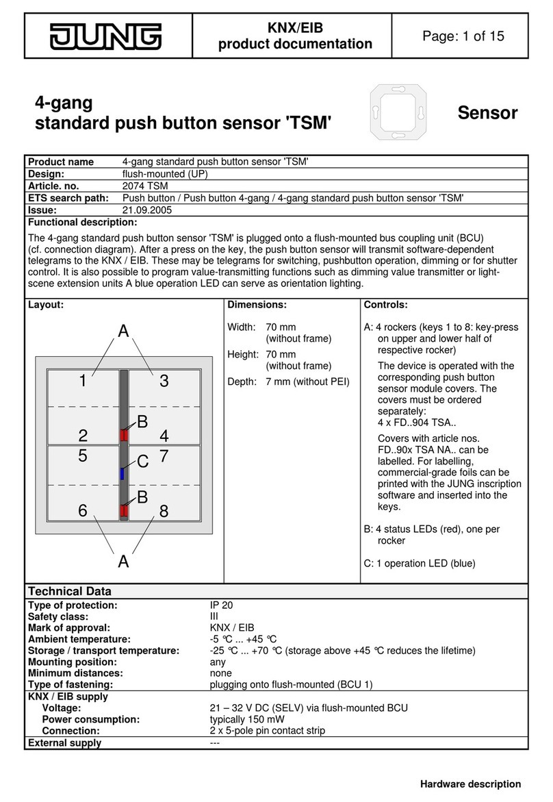
Jung KNX WS 10 D User manual

Jung
Jung FW180WW User manual

Jung
Jung LES01 User manual

Jung
Jung 5232 Series User manual

Jung
Jung RW 95 User manual

Jung
Jung SCHUKO 1520-15 Series User manual

Jung
Jung 65 WIS User manual

Jung
Jung 2074 TSM User manual

Jung
Jung TK AS AL 114 User manual

Jung
Jung 1792HTBT User manual