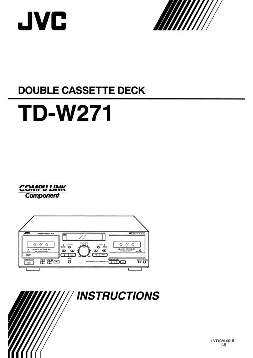
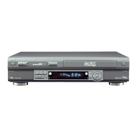
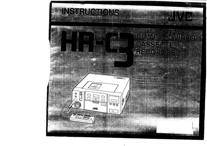
JVC SR-W320U User manual

INSTRUCTIONS
JVC
R-W320U
Hi-Vision
VIDEO
CASSETTE
RECORDER
|
W’IVHS)
povsp
SVHS
Alg-lF
S
i
For
Custormer
Use:
Enter
below
the
Serial
No.
whic)
is
located
on
the
rear
of
the
cabint.
Retain
this
inforamtion
for
future
reference.
|
Model
No.
SR-W320U
Serial
No.
=
|
$L96020

SAFETY
PRECAUTIONS
RISK
OF
ELECTRIC
SHOCK,
|
DO
NOT
OPEN
.
CAUTION:
TO
REDUCE
THE
RISK
OF
ELECTRIC
SHOCK.
DO
NOT
REMOVE
COVER
(OR
BACK).
NO
USER-SERVICEABLE
PARTS
INSIDE.
REFER
SERVICING
TO
QUALIFIED
SERVICE
PERSONNEL
The
lightning
flash
with
arrowhead
symbol,
within
an
equilateral
triangle,
is
intended
to
alert
the
user
to
the
presence
of
uninsulated
“dangerous
voltage”
within
the
product's
enclosure
that
may
be
of
sufficient
magnitude
to
constitute
a
risk
of
electric
shock
to
persons.
The
exclamation
point
within
an
equilateral
triangle
is
intended
to
alert
the
user
to
the
presence
of
important
operating
and
maintenance
(servicing)
instructions
in
the
literature
accompanying
the
appliance.
WARNING:
TO
PREVENT
FIRE
OR
SHOCK
HAZARD,
DO
NOT
EXPOSE
THIS
APPLIANCE
TO
RAIN
OR
MOISTURE.
This
video
cassette
recorder
should
be
used
with
AC
120V~,
60
Hz
only.
CAUTION:
To
prevent
electric
shocks
and
fire
hazards,
do
NOT
use
any
other
power
source.
ATTENTION
This
product
complies
with
D.O.C
Limits
(C.R.C.,
C.
1374)
pertaining
to
Class
A
digital
apparatus.
ATTENTION
Ce
produit
est
conforme
aux
normes
du
M.D.C
(C.R.C.,
ch.
1374)
s’appliquant
aux
appareils
numériques
de
Classe
A.
NOTE
This
equipment
has
been
tested
and
found
to
comply
with
the
limits
for
a
Class
A
digital
device,
pursuant
to
Part
15
of
the
FCC
Rules.
These
limits
are
designed
to
provide
reasonable
protection
against
harmful
interference
when
the
equipment
is
operated
in
a
commercial
environment.
This
equipment
generates,
uses,
and
can
radiate
radio
frequncy
energy,
and
if
not
installed
and
used
in
accordance
with
the
instruction
manual,
may
cause
harmful
interference
to
radio
communications.
Operation
of
this
equipment
in
a
residentia!
area
is
likely
to
cause
harmful
interference
in
which
case
the
user
will
be
required
to
correct
the
interference
at
his
own
expense.
CAUTION
CHANGES
OR
MODIFICATIONS
NOT
APPROVED
BY
JVC
COULD
VOID
USER’S
AUTHORITY
TO
OPERATE
THE
EQUIPMENT.
NOTE:
The
rating
plate
and
the
safety
caution
are
on
the
rear
of
the
unit.
When
you
are
not
using
the
video
recorder
for
a
long
period
of
time,
it
is
recommended
that
you
disconnect
the
power
cord
from
the
AC
outlet.
ssmmmmmmmmnen
=
enanocmin
=
itacamcte
©
imecemamemn
emcee
aint
ehmtacitee
nonim
enpm
.
Timer-Programmed
Recording
.
Playback......
TABLE
OF
CONTENTS
Precautions
.........:.cccccssesensrsserseestsesesrseseseeesoraes
4
Features.
VCR
.......
Video
Cassettes...
Head
Cleaning
Recording
Modes
and
Types
of
the
Cassettes
...6
Loading
and
Unloading
the
Cassette
..................
N
Controls
and
COMNECHOLS
.....sssersessecerensenseennensee
8
Front
Panel
:...
Rear
Panel
....
Indicators
and
Displays
..........
iacchoads
erenenonsnests
14
What
Is
Shown
on
the
Front
Display
Window
...
14
Preparations
....
Connections
..
Time
Setting
..
Recording
Basic
Operations
.
Retake
Facility
..
Blank
Search
Facility
.
Al
Auto
Calibration
Timer-Programmed
Recording
.
Check,
Correct
and
Cancel
of
the
Preset
Programs
.........:.ccccceecceteeeeeeeeeeeeeees
22
Basic
Procedure
...
Special
Playback
Procedures
Index
Search
0.0...
cceeseeeseses
Next
Function
222.0...
ce
eeeesee
Adjustment
of
the
Playback
Picture
.
Tape
Dubbing
................ccscssessssssrsnssieeseenseesnens
32
When
Playing
Back
on
SR-W320U
and
Recording
on
Another
Unit
....
When
Playing
Back
on
Another
Unit
and
Recording
on
SR-W320U
..........eccceeessteesseaten
33
When
Playing
Back
on.a
Video
Movie
and
Recording
on
SR-W320U..........
fehl
ee
a
emibnsaeh
34
7
;
11.
Appendix
~
Technical
Guide
9
RS-232C
Interface...
sscssescscssccessosessensensee
35
RS-232C
Protocol
Commands
10
Troubleshooting
..........cssccsscensonccsntenseasessesene
40
12
Specifications
.............00000
siatadelveceseosnatuavecrarsces
47.
erent
eR,
eT
—,
:
ieee
sme
an
ptcoeerteane
ts
'
E
;
}
i
f
;
’
}
7}
5

1__PRECAUTIONS
Asari
FEATURES
e@
W-VHS
format
HD
mode
offers
high-definition
recording
and
playback
of
high-vision
signals
on
a
base
band.
@
W-VHS
format
SD
mode
also
available
to
ensure
high-quality
picture
for
the
existing
TV
format
sources.
@
W-VHS
metal
compatible
high-power
Sendust
heads
@
HD
super
solid
DD
mechanism
enables
metal
tapes
to
run
with
a
greater
stability.
@
The
existing
VHS/S-VHS
video
can
be
recorded
and
played
back
with
a
superb
quality.
®
Built-in
RS-232C
enables
you
to
externally
control
this
unit
from
your
personal
computer.
With
this
video
cassette
recorder,
you
can
enjoy
the
HD
and
SD
modes
of
W-VHS
video.
Be
sure
to
use
cassette
tapes
marked
with
S|VHS).
Since
the
VHS
mode
and
S-VHS
mode
are
also
available,
use
video
cassettes
marked
with
S$/VHS]
or
when
you
want
to
enjoy
these
modes.
When
executing
HD
recording
with
this
unit,
connect
to
a
high
vision
TV
with
a
built-in
MUSE
decoder
having
HD
output
connectors
(Y,
PB,
PR).
When
any
other
high-vision
TV
is
in
use,
you
have
to
connect
a
commercially
available
MUSE
decoder.
What
is
HD
mode?
(HD
denotes
High
Definition)
In
HD
mode,HDTV
signals
are
recorded
using
multiple
tracks,
HDTV
signal
was
originally
developed
by
NHK
of
Japan,
and
it
stands
for
High-Definition
Television.
HDTV
is
a
next
generation
broadcasting
system
which
eabies
high-definition
picture
quality
in
comparision
to
conventional
NTSC
system.
What
is
SD
mode?
(SD
denotes
Standard
Definition)
In
SD
mode
standerd
TV
signals
are
recorded
on
a
single
track
with
high
picture
quality
and
long
recording
times.
1
PRECAUTIONS
VCR
@
Avoid
using
the
recorder
in
places
subject
to
the
following
conditions:
—
extreme
heat,
cold,
or
humidity,
—
dust,
~
vibrations,
and
—
poor
ventilation.
©
Be
careful
of
moisture
condensation.
Do
not
use
the
recorder
immediately
after
moving
it
from
a
cold
place
to
a
warm
place.
The
water
vapor
in
warm
air
will
condense
on
the
still-cold
video
head
drum
and
tape
guides
and
may
cause
damage
to
the
tape
and
the
recorder.
@
Handle
the
recorder
carefully.
*
Do
not
block
the
ventilation
openings.
*
Do
not
place
anything
heavy
on
the
recorder.
¢
Do
not
place
anything
which
might
spill
on
the
top
cover
of
the
recorder.
*
Use
in
horizontal
(flat)
position
only.
@
During
transportation,
*
Avoid
violent
shocks
to
the
recorder
during
packing
and
transportation.
*
Before
packing,
be
sure
to
remove
the
cassette
from
the
recorder.
Video
cassettes
@
Use
video
cassettes
marked
with
WHS
/
SVHS!/
(WiIS|
with
this
unit.
C-cassettes
can
be
used
with
a
C-cassette
adapter
(SA-CP11U)
connected.
@
Video
cassettes
marked
with
WIWHS|
are
exclusively
for
use
with
a
video
cassette
recorder
marked
with
WWHS!.
Loading
such
cassettes
into
existing
S-
VHS
or
VHS
cassette
recorders
may
cause
a
damage
to
the
machine.
e
Any
cassette
is
provided
with
a
safety
tab
for
protecting
it
from
accidental
erasure.
The
cassette
with
its
safety
tab
set
at
a
protective
position
automatically
starts
playback
when
loaded
into
a
machine.
W-VHS
cassettes
Slidable
safety
tab.
Protected
Unprotected
position
position
cof
og
com>)
[ai
aD
a>
Fd
Fd
oO
oO
S-VHS,
VHS
cassettes
*
To
prevent
accidental
erasure,
remove
the
cassette’s
safety
tab.
*
To
record
on
a
cassette
whose
safety
tab
has
been
removed,
cover
the
hole
with
adhesive
tape.
e
Reverse
side
of
a
cassette
is
not
usable.
e
Before
putting
the
cassette
into
storage,
make
sure
that
the
tape
is
uniformly
wound
up
to
its
beginning.

1
PRECAUTIONS
Head
cleaning
Perform
head
cleaning
even
20
hours
to
enjoy
clear
pictures.
Video
heads
get
soiled
with
repeated
recording
and
playback,
resulting
in
rough,
uneven
picture.
Perform
cleaning
of
the
tape
transport
mechanism
every
20
hours
with
the
provided
head
cleaning
tape
dedicated
to
W-VHS.
:
How
to
use
the
cleaning
tape
1.
Load
the
W-VHS
dedicated
head
cleaning
tape.
2.
Press
the
PLAY
button
and
then
STOP
button
after
about
30
seconds.
Aad
Unload
the
head
cleaning
tape
and
execute
a
usual
recording
and
playback
procedure
on
a
W-
VHS
cassette
to
see
if
audio/visual
quality
has
been
recovered.
4,
If
tape
quality
does
not
pick
up,
repeat
the
procedures
1.
and
2.
once
or
twice.
Cautions
@
Do
not
rewind
the
cleaning
tape
after
every
use
(for
about
30
seconds).
You
have
only
to
start
at
the
position
where
the
tape
stopped
in
previous
cleaning.
Rewind
to
the
beginning
when
the
tape
has
been
used
to
an
end.
@
30
seconds
are
enough
for
one
run
of
the
cleaning
tape.
To
keep
running
the
tape
for
longer
than
45
seconds
may
damage
the
heads.
@
If
sound
and
picture
quality
does
not
recover
with
the
cleaning
procedures
repeated
three
times,
there
may
be
some
other
causes
of
trouble.
Consult
your
JVC
dealer.
®@
The
W-VHS
dedicated
cleaning
tape
can
be
used
100
times.
@
Recording
or
playback
is
not
possible
on
the
cleaning
tape.
@
Do
not
use
any
cleaning
tape
other
than
the
W-
VHS
dedicated
cleaning
tape
for
this
machine.
®@
The
W-VHS
dedicated
cleaning
tape
can
be
used
only
with
the
video
cassette
recorder
marked
with
wh.
RECORDING
MODES
AND
TYPES
OF
THE
CASSETTES
Recording
modes
available
depend
on
the
types
of
the
cassette
in
use.
Tapes
in
use
iZ
Recording
modes
Recording
speed
Remarks
W-VHS
HD
SP
S-VHS/VHS
recording
not
possible.
SD
EP
S-VHS
SP/EP
Selectable
HD/SD
recording
not
possible.
SP/EP
Selectable
SP/EP
Selectable
Cautions
*
HD
recording
at
EP
mode
is
not
possible.
*
SD
recording
at
SP
mode
is
not
possible.
HD/SD/SVHS
recording
not
possible.
eZ
end
Perea
erate
ohn
Pee
eweccten
evenmenecsen
tn
canes
ae
asi
re’
1
PRECAUTIONS
LOADING
AND
U
ING
THE
CASSETT
OPEN/CLOSE
button
TIMER
tamp
TIMER
button
Loading
1.
Press
[OPEN/CLOSE]
button
to
open
the
door.
2.
Insert
the
cassette.
«
Slowly
push
the
center
with
its
visible
tape
side
up.
©
The
door
automatically
closes.
*
Counter
display
turns
0:00:00.
¢
The
cassette
with
its
safety
tab
removed
automatically
starts
playback.
Cautions
¢
Keep
your
hand
or
other
foreign
substances
away
from
the
loading
slot.
Take
special
care
of
young
children
to
protect
their
hands
from
the
door.
If
a
hand
or
finger
should
be
caught,
the
door
opens
after
several
seconds.
«
When
the
cassette
automatically
comes
out,
insert
it
again
after
several
seconds.
Unloading
1.
Press
[OPEN/CLOSE]
button.
The
door
opens
and
the
tape
comes
out.
The
cassette
cannot
be
removed
while
the
[TIMER]
tamp
is
lit.
Press
the
[TIMER]
button
and
make
sure
the
[TIMER]
lamp
is
out,
then
remove
the
cassette.
2.
Press
[OPEN/CLOSE]
button.
The
door
closes.
ements
eon
tancating
oleate
a

@
[POWER]
button/lamp
Press
to
turn
the
power
on
and
off.
The
lamp
lights
when
the
power
is
on.
@
Tape
loading
slot
door
©
Video
unit
display
window
Displays
the
operational
state
of
the
recorder,
counter
and
clock
digits.
@
[TIMER]
lamp
Lights
red
when
the
timer
preset
recording
stands
by.
@
[BLUE
BACK]
lamp
Lights
green
when
the
BLUE
BACK
switch
is
at
AUTO.
@
[S-VHS
TBC]
lamp
Lights
green
when
the
S-VHS
TBC
switch
is
at
ON.
@
[W-VHS
TAPE
IN]
lamp
Lights
red
when
the
W-VHS
tape
is
in
the
recorder.
©
[HD]
tamp
Lights
red
when
HD
mode
is
selected
with
a
W-
VHS
tape
in
use
or
when
a
HD-recorded
tape
is
played
back.
©
[SD]
lamp
Lights
green
when
SD
mode
is
selected
with
a
W-
VHS
tape
in
use
or
when
a
SD-recorded
tape
is
played
back.
@®
[S-VHS]
lamp
Lights
green
when
the
S-VHS
recording
switch
is
at
AUTO
with
an
S-VHS
tape
in
use
or
when
an
S-
VHS
recorded
tape
is
played
back.
@
[SQUEEZE
ID]
lamp
Lights
when
*
the
SQUEEZE
ID
switch
is
at
AUTO
and
S1
signal
is
fed
to
the
external
input
signal
connector.
*
the
tape
recorded
in
full
mode
is
played
back,
provided
that
the
S1
video
signal
is
recorded
together.
¢
the
SQUEEZE
ID
switch
is
set
at
ON.
Full
Mode.
4
a
Entered
to
fit
the
pi
spect
ratio
of
16
29,
such
as
high-vision
picture,-within
aspect
2
fatio
of
4:3,
feeulting
in
in
a
verically
eet
“picture,
">"
Si
Picture
Signal
>
Signal
for
discriminating
whether.
or
not
the.
_
Picture
i
is
in
full
mode
superimposed
onthe
S
hoftzontally
wide
picture
when
played
back.
2
CONTROLS
AND
CONNECTORS
Front
panel
@
[AUTO
CAL]
auto
calibration
lamp
Flickers
green
during
auto
calibration
going
on
and
lights
when
it
is
finished.(See
page
20)
®
[AT]
auto
tracking
lamp
Lights
or
flickers
green
during
auto
tracking
going
on.
@®
[PLAY]
button
Press
to
play
back
the
cassette.
®
[REW})/[FF]
button
Press
to
rewind
or
fast
forward.
@
[OPEN/CLOSE]
door
button
Press
when
opening
or
closing
the
door
and
removing
the
cassette.
@
[STOP]
button
Press
to
stop
any
operation
of
VCR.
@®
LINE3
IN/OUT
connectors
Receives
and
sends
external
video
and
audio
signals.
Switchable
between
input
and
output
with
the
IN/
OUT
SELECT
switch
@.
S1
VIDEO:
For
input
and
output
of
S1
video
signal
VIDEO:
For
input
and
output
of
video
signal
(RCA)
(MONO)
L:
For
input
and
output
of
audio
signal
(left).
If
the
sound
is
monaural
with
a
single
cable,
plug
it
into this
connector,
and
equal
audio
signals
are
recorded
for
teft
and
right.
R:
For
input
and
output
of
audio
signal
(right).
St
video
signal
is
given
priority
to
a
standard
video
signal.
@®
[REMOTE
PAUSE]
input
connector
Connect
the
remote
pause
cable
to
this
connector
when
editing
with
the
JVC
video
movie.
This
connector
is
given
priority
to
the
remote
pause
connector
at
rear
panel.
(See
page
34)
@
[IN/OUT
SELECT]
switch
Selects
between
input
and
output
of
the
three
external
input/output
connectors
®.
@
[BLUE
BACK]
switch
AUTO:
Blue
screen
comes
up
when
there
is
no
input
signal.
OFF:
No
bule
screen
comes
up.
@
[S-VHS
TBC]
switch
Turns
on
and
off
the
TBC
(Time
Base
Corrector).
This
switch
is
disabled
in
HD/SD
mode.
ON:
Normally
set
to
ON.
Picture
distortion
is
corrected
to
provide
a
stable
picture
quality
during
playback.
OFF:
Set
to
OFF
when
playing
back
the
tape
with
much
noise.
®
[S-VHS
REC]
switch
Turns
on
and
off
the
S-VHS
recording
facility.
AUTO: S-VHS
recording
takes
place
automatically
with
the
S-VHS
cassette
loaded
and
VHS
recording
with
the
VHS
cassette
loaded.
OFF:
VHS
recording
takes
place
regardless
of
the
type
of
cassette
loaded.
@®
[SQUEEZE
ID]
switch
Selects
the
way
S1
video
signal
is
recorded.
AUTO:
Input
signal
is
recorded
as
it
is.
ON:
S1
video
signal
is
forcedly
recorded.
@®
[3DY/C
SELECT]
Select
the
right
recording
setup
depending
on
in
what
condition
the
picture
to
be
recorded
is.
STD:
Usually
select
this
setup.
MOVE:
Select
this
for
a
picture
with
a
lot
of
motion.
High
SN:
Select
this
for
a
picture
with
a
lot
of
noise.
@®
[PICTURE]
adjust
knob
During
playback,
turn
this
knob
clockwise
to
obtain
a
SHARP
picture
and
counterclockwise
for
a
SOFT
picture.
@
[REC
LEVEL}/[BALANCE]
adjust
knob
Adjusts
HiFi
recording
level
and
the
balance
between
right
and
left
channels.
Carefully
adjust
this
knob,
as
too
low
a
recording
level
may
lead
to
a
greater
noise
and
too
high
a
jevel
may
cause
a
distortion.
®
[
VOLUME]
adjust
knob
Adjust
the
sound
level
of
headphone
connected
to
the
HEADPHONE
connector.
@®
[PHONES]
connector
Accepts
the
mini
plug
type
headphone.

2
CONTROLS
AND
CONNECTORS
Front
panel
VG
srwecou
vision
vireo
casserre
neconven
os
ees
teem
sunmce
"ETO
@
CLOCK
setup
buttons
Used
to
set
up
clock
.
(See
page
17).
CLOCK
ADJUST
Starts
or
ends
the
time
setting
mode.
SET
-/+
Sets
day
and
time.
SELECT
Fix
the
selected
data.
@
[AUTO
CAL]
button
Automatically
adjust
the
recording
level
depending
on
the
tape
characteristics.
This
facility
is
disable
when
a
W-VHS
is
in
use.
(See
page
20).
@
[COUNTER
RESET]
button
Resets
the
tape
counter
display
to
0:00:00.
@®
[TRACKING]
button
++
Suppresses
the
disturbances
appearing
on
the
picture
when
the
tape
recorded
on
another
machine
is
played
back
(or
put
on
slow
playback).
AUTO
TRACKING:
Turns
on
and
off
the
auto
tracking
facility.
@
[INPUT
SELECT]
button
Selects
among
video
signals
L1, L2,
L3
and
HD.
Every
time
the
button
is
pressed,
the
signals
shift
LINE
1
(L1)
>
LINE
2
(L2)
>
LINE
3
(L3)
>
HD
one
after
another.
10
re
®
[SP/EP
(HD/SD)]
select
button
Selects
between
recording
speeds.
®
[BLANK
SEARCH]
button
Searches
a
non-recorded
(blank)
section
of
the
tape.
(See
page
19)
@
[HD
INPUT]
button
Converts
the
input
signal
to
an
HD
input.
With
the
INPUT
SELECT
switch
®
pressed,
other
input
signals
can
be
entered.
@®
[RECORD]
button
Press
to
start
recording.
®
[VARIABLE
SEARCH]
button
Changes
the
search
speed
upon
every
pressing
the
button.(See
page
26)
@
[INDEX
SEARCH]
button
Press
to
start
index
search.
Searches
the
start
of
recorded
or
timer-recorded
section
or
the
section
indicated
with
INDEX
signal,
where
normal
playback
starts.
(See
page
27)
@
[PAUSE/STILL]
button
Press
to
pause
the
recording
or
change
the
piayback
picture
to
a
still
picture.
Canceled
by
pressing
the
PLAY
button.
2
CONTROLS
AND
CONNECTORS
Front
panel
@
[HIF!
AUD
OUT
SELECT]
button
Selects
HiFi
audio
sources
to
be
played
back.
Every
pressing
the
button
changes
right
and
left
audio
->
left
audio
—>
right
audio
one
after
another.
@
[DISPLAY]
button
SELECT:
Every
pressing
the
button
changes
the
display
window
between
several
sets:
Tape
counter/mode
display
—>
hour/
mode
display
—
audio
level
indication
...
ON/OFF:
Turns
the
display
on
and
off.
@
[AUDIO
OUT
SELECT]
button
Selects
audio
to
be
played
back.
Every
pressing
the
button
changes
HiFi
->
Normal
-»
Mix
(HiFi
and
Normal)
one
after
another.
@®
[EDIT]
button
Press
to
play
back
or
record
with
a
picture
quality
suitable
for
dubbing
or
editing.
@®
[INDEX]
button
Record
and
erases
the
index
signal.
MARK:
Record
VISS
(INDEX)
ERASE:
Erases
VISS
(INDEX)
(See
page
27)
@
[Al
AUTO]
button
Adjust
the
picture
to
a
desired
video
quality.
Every
pressing
the
button
changes
Al
AUTO.
@®
Timer
program
preset
button
PROGRAM
:
Start
programming
CHECK/CORRECT:
Check
and
correct
the
programmed
data.
CANCEL:
Press
to
cancel
the
programmed
data.
This
can
be
used
as
a
tape
counter
reset
button,
unless
timer
programing
is
in
operation.
Sets
the
date,
hour
and
recording
speed.
SELECT:
Selects
the
set
data.
SET
-/+:
TIMER:
Press
to
keep
the
timer-programmed
recording
at
standby
or
cancel
it.
(See
page
21)

2
CONTROLS
AND
CONNECTORS
Rear
Panel
@
Remote
pause
input
connector
Connect
the
remote
pause
cable
to
this
connector
when
editing
with
the
JVC
video
movie.
The
remote
pause
connector
on
the
front
panel
is
given
priority.
@
Remote
control
connector
Connect
the
remote
control
cable
when
externally
controlling
the
machine
with
optinal
remote
control
unit
(RM-G30U).
@
Auto
door
close
switch
ON:
When
the
door
is
left
open
for
one
minute,
the
door
automatically
closes.
OFF:
The
door
does
not
automatically
close.
Use
the
OPEN/CLOSE
button
for
operation
of
the
door.
©
Audio
input
connectors
1,2
Receive
the
audio
signal
from
an
external
audio
unit.
When
dubbing
a
tape,
connect
the
playback
machine
to
this
connector.
@
Audio
output
connectors
1,2
Output
the
audio
signal
to
an
external
audio
unit.
Connect
such
a
machine
as
TV
with
audio
input
connectors.
When
dubbing
a
tape,
connect
the
recording
machine
to
this
connector.
12
©
S1
video
input
connectors
1,
2
Receive
S
or
S1
video
signals.
Connect
a
playback
machine
to
this
connector
for
dubbing.
@
Video
input
connectors
1,2
Receive
composite
video
signals.
Connect
a
playback
machine
to
this
connector
for
dubbing.
©
S1
video
output
connectors
1,2
Output
S
video
or
S1
video
output
signal.
Connect
such
a
machine
as
TV
with
video
input
connectors.
When
dubbing
a
tape,
connect
the
recording
machine
to
this
connector.
©
Video
output
connectors
1,2
Output
composite
video
output
signals.
Connect
such
a
machine
as
a
TV
with
video
input
connectors.
When
dubbing
a
tape,
connect
the
recording
machine
to
this
connector.
@
AC
IN
socket
Connect
to
120VAC,60
Hz
power
outlet
using
the
provided
power
cord.
®
Fans
Prevents
abnormal
temperature
rise
in
the
unit,
so
neither
remove
nor
block
it.
They
go
on
running
until
the
temperature
drops
enough
even
if
the
power
is
turned
off.
2
CONTROLS
AND
CONNECTORS
a
Rear
Panel
@
RS-232C
connector
Connect
a
RS-232C
cable
to
control
this
unit
from
a
personal
computer.
Use
a
cross
cable.
@®
[HD
AUDIO
IN
Jconnector
Connect
to
the
audio
output
connector
of
a
MUSE
decoder
or
the
MUSE
decoder
audio
output
connector
of
a
high
vision
TV.
@
[AUDIO
OUT
4]
connectors
Connect
to
the
audio
input
connectors
of
a
high
vision
TV.
@®
[HD
VIDEO
IN}
connector
Connect
to
the
output
connector
of
a
MUSE
decoder
or
the
MUSE
decoder
output
connector
of
a
high
vision
TV.
@®
[HD
VIDEO
OUT
]
connector
Connect
to
the
W-VHS
input
connector
or
HD
input
connector
of
a
high
vision
TV.
@®
Ground
connector
a
Take
care
of
the
following
points
werier
“connecting
to
the
audio
input
epaector
2
and.
“:s-
the
HD
audio
input
connector.::
. 2:
When
connected
to
the
right
ahd
lett
channels
‘ofthe
HD
audio
input
connector
and
to
the
“=
audio
input
connector
2,
the
audio
input
signal
=
at
the
HD
audio
input
connector
is
given
priority
~~
even
if
the
channel
L2
has
been.
selected.
=:
TO
receive
audio
signal
through
the
audio
input
=.
eonnettor
2,
unplug
the
cable.
connectad
to
the
~=/HD
audio
input
connector.’
2.
When
connected
only
to
the
audio
input
*
.eonnector
2;
the
audio
aa
is
received
also
when
HD
input
is
received.
13

3__
INDICATORS
AND
DISPLAYS
What
is
shown
on
the
front
display
window
SVE
sev
220
ven
veo
casserre
neconpen
+
4
3
SQQHOGD
SG
Pressing
the
AUDIO
OUT
SELECT,
HIFI
AUDIO
OUT
SELECT
and
the
DISPLAY
buttons
changes
the
front
window
display
among
the
following
sets
of
display
data.
[Example
of
display]
®
clock
display
@
VTR
operation
display
Audio
leval
|
ov
Con
14:30)
(TAPE
IN
@
Extinput
@
REC
speed
DISPLAY
SELECT
HiF
t
AUD
OUT
SELECT
2
VCR
operation
display
TAPE
IN
Cassette
is
loaded
EJECT
Cassette
being
removed
REC
Recording
PAUSE
Recording
at
pause
FF
Fast
Forward
REW
Rewind
FWD
Fast
forward
playback
REV
Rewind
playback
STILL
Still
picture
(forward)
-STILL
|
Still
picture
(reverse)
SLOW
Slow
playback
(forward)
-SLOW
Slow
playback
(reverse)
vISS2
VHS
index
search
BLANK
Blank
search
DEW
Machine
is
dewed
DISPLAY
SELECT
button
AUDIO
OUT
SELECT
button
HIF)
AUD OUT
SELECT
button
Example
of
display
1
Clock
display
Shows
date
and
time
Sun:
Sunday
Thu:
Thursday
Mon:
Monday
Fri:
Friday
Tue:
Tuesday
Sat:
Saturday
Wed:
Wednesday
Counter
display
*
Counter
display
flickers
when
an
unrecorded
section
is
reached
during
fast
forward
or
rewind.
PLAY
flickering
EJECT
flickering
|
PLAY
next
function
memory*
EJECT
next
function
memory*
*
Next
function
memories
include
timer
standby
and
power
“off”
as
well,
but
they
are
not
indicated
on
the
front
display
window.
3
External
input
Displays
the
external
input
connectors
selected
Li
LINE
(S1
video)
input
connector
1
L2
LINE
(S1
video)
input
connector
2
L3
LINE
(Si
video)
input
connector
3
HD
HD
input
connector
14
ead
rercanewtein remncesnston
erastoccoe
Proven,
sanctions
seemarsmmate
emcee,
a
a
semen
3
INDICATORS
AND
DISPLAYS
4
Recording
mode
SP
Standard
(in
HD
mode)
EP
Extended
(in
SD
mode)
Other
display
data
Next
function
super
rewind
[Example
of
display]
VISS
operation
display
[Example
of
display]
VISS
MARK
VISS
in
operation
VISS
MARK
flickering
Index
signal
being
recorded
VISS
ERASE
flickering
Index
signal
being
erased
15
esr
ered
eet
naetanraeoin

4
PREPARATIONS
The
SR-W320U
can
be
connected
to
the
following
units.
Rear
panel
Connection
to
a
high
vision
TV
Video
signal
connection
Audio
signal
connection
HD
audio
output
connector|__]
High
vision
TV
To
HD
audio
input
connector
To
HD
video
input
connector
HD
video
output
connector
Connection
to
a
monitor
TV
Video
signal
connection
Audio
signal
connection
To
audio
input
connector
Audio
output
connector
Monitor
TV
To
S1
video
input
connector
S1
video
output
connector
Connection
to
a
personal
computer
through
RS-232C
Personal
computer
To
RS-232C
connector
RS-232C
connector
16
4
PREPARATIONS
Time
Setting
IETS
DOW
asap
ae
se
~
Thu
15:35
1
3,5,7
46
2,8
L1
SP
(Example)
When
setting
to
Thursday
35
minutes
past
3
o’clock
pm.
_
Turn
the
power
on.
nN
Press
CLOCK
ADJUST
button.
Date
display
flickers.
7
Set
the
minute
with
+
or
—
button.
8
Press
CLOCK
ADJUST
button.
The
clock
starts
with
Thursday
3:35
pm,
simultaneously
as
the
button
is
pressed.
3
Set
the
date
with
+
or
—
button.
4
Press
SELECT
button.
Hour
display
flickers.
Ls
if
there
is
no
time
sat,
0:00
flickers.on
the
front
panel
window
display:
‘This
occurs
also
when
5
Set
the
hour
with
+
or
—
button.
power:
breakdown
stays
longer
than
80.minutes
6
Press
SELECT
button.
Minute
display
flickers
17

3__RECORDING
Basic
Operations
SP/EP
(HD/SD)
Preparations
1
Turn
the
power
on.
2
Select
the
recording
mode.
Which
mode
is
available
depends
on
the
type
of
the
cassette
in
use.
Cassette
in
use
Recording
mode
HD
mode
SD
mode
S-VHS
mode
VHS
mode
VHS
mode
HD
mode
a.
Press
the
HD
INPUT
button.
b.
Load
the
W-VHS
tape.
Then,
HD
lamp
lights
and
SP
is
shown
on
the
front
window
display.
SD
mode
a.
Select
L1,
L2
or
L3
with
INPUT
SELECT
button.
b.
Load
the
W-VHS
tape.
Then,
SD
lamp
lights
and
EP
is
shown
on
the
front
window
display.
18
HI-FIAUD
OUT
AUDIO
OUT
SELECT SELECT
Co
GS
DISPLAY
S-VHS
mode
a.
Select
Lt,
L2
or
L3
with
INPUT
SELECT
button.
b.
Load
the
S-VHS
tape.
c.
Select
recording
speed
with
the
SP/EP
(HD/SD)
button.
Every
pressing
this
button
changes
the
SP
-
EP
—
SP.
d.
Set
the
[S-VHS
REC]
switch
to
AUTO.
The
[S-
VHS]
jamp
lights.
VHS
mode
a.
When
using
a
S-VHS
tape,
set
the
S-VHS
REC
switch
to
OFF.
The
[S-VHS]
jamp
goes
off.
With
a
VHS
tape
loaded,
the
VHS
mode
is
automatically
entered.
b.
Select
recording
speed
with
SP/EP
button.
Set
an
optimum
recording
level
with
the
AUTO
CAL
button
as
required.
(See
page
20).
This
facility
does
not
work
for
the
W-VHS
tape.
5
RECORDING
ES
a
TE
DE
IT
Basic
Operations
4
Adjust
the
HiFi
recording
level.
5
Start
recording.
a.
Call
up
the
audio
level
meter
display
with
the
a.
Press
the
REC
button,
whereupon
recording
DISPLAY
SELECT
button.
starts.
b.
Select
HiFi
audio
with
the
AUDIO
OUT
SELECT
b.
Press
the
PAUSE/STILL
button
for
a
brief
pause
button.
This
shows
the
HiFi
audio
level
meter
of
recording.
display.
(See
page
14).
c.
Pressing
the
PLAY
button
resumes
recording.
c.
Adjust
the
recording
level
and
L/R
balance.
d.
Press
the
STOP
button
to
bring
recording
to
an
While
checking
with
the
audio
level
meter,
end.
adjust
with
the
REC
LEVEL
and
BALANCE
knobs,
until
the
thick
bars
on
the
display
occasionally
swing.
Perform
adjustment
carefully,
as
too
low
a
recording
level
may
lead
to
a
greater
noise
and
too
high
a
level
may
cause
a
distortion.
Retake
Function
You
can
cut
the
unnecessary
part
of
the
program
during
recording.
This
facility
does
not
work
when
using
a
W-VHS
tape.
End
of
Unnecessry
part]
Unnecessry
part
Program
to
program
|tobe
recorded
|
to
be
recorded
|
be
continued
a.
With
the
pause
mode
entered,
keep
pressing
the
Recorded
section
REW
or
FF
button.
The
tape
is
played
back
at
a
normal
PLAY
speed.
b.
Leave
your
hand
off
the
button
at
the
start
of
the
Resume
recording
with
the
PLAY
button.
unnecessary
part
(where
you
want
to
adjoin
the
program).
Pause
mode
resumes
where
your
hand
End
of
Program
to
be
continued.
has
left
the
button.
slay
c.
Press
the
PLAY
button
at
the
part
of
the
program
you
want
to
continue
recording.
Recording
resumes.
with
the
FF
or
REW
button.
Blank
Search
Function
Used
to
search
the
unrecorded
section
of
the
tape.
a.
With
the
stop
mode
entered,
press
the
BLANK
SEARCH
button.
Search
stops
where
the
unrecorded
section
is
found.
b.
Press
the
STOP
button
if
you
want
to
cancel
biank
search.
Pesan,
mecca
nd
reenact
ecnnasannes,
nen
ect
ehe,
eugene,
oe

5
RECORDING
Al
Auto
Calibration
COUNTER
RESET
AUTO
TRACKING
INPUT
SELECT
HO
INPUT
AUTO
CAL
TRACKING
0
PAUSE/STILL
Checks
the
characteristics
of
the
tape
in
use
and
sets
the
recording
level
to
an
optimum
in
dependence
on
such
characteristics.
This
facility
does
not
work
for
the
W-VHS
tape.
Preparations
Al
auto
calibration
is
recorded
on
a
section
of
the
tape
to
check
up
the
tape
characteristics.
{tis
recommended
to
perform
this
recording
on
a
section
you
do
not
mind
erasing.
Make
sure
that
the
tape
is
unprotected
(with
the
safety
tab).
Procedures
1
Load
the
tape.
2
Select
recording
speed
with
the
SP/EP
button.
3
Engage
the
Record
Pause mode.
While
pressing
the
PAUSE/STILL
button,
press
REC
button.
20
4
Keep
pressing
the
AUTO
CAL
button
until
the
AUTO
CAL
lamp
flickers.
The
machine
automatically
checks
the
tape
characteristics.
The
record
pause
mode
resumes
after
completion
of
adjustment.
(Approx.
10
seconds)
There
comes
no
audio
during
this
operation.
input
select
is
also
disabled.
a
Press
the
PLAY
button
if
you
want
to
immediately
start
recording.
When
the
tape
is
ejected,
the
AUTO
CAL
lamp
goes
off
and
the
Al
auto
calibration
mode
is
canceled.
6
_TIMER-PROGRAMMED
RECORDING
Timer-Programmed
Recording
1
5
4,6
5
Eight
programs
can
be
preset
for
two
weeks
ahead.
Example:
Preset
the
program
7:00
to
9:00
pm
on
Thursday
on
L1
input
at
SP
mode.
1
Turn
the
power
on.
2
Make
sure
of
the
present
time
on
the
front
panel
display
window.
3
Load
a
tape
with
safety
tab
(on
the
REC
side
for
W-VHS
tape).
4
Press
the
PROGRAM
button.
5
Set
the
date,
start
time,
end
time,
input
select
and
recording
speed.
Date
a.
Make
sure
that
the
date
display
flickers.
b.
Set
the
date
with
the
SET
+
button.
c.
Pressing
the
+
button
changes
Sunday
>
Saturday
in
the
first
week,
Sunday
—
Saturday
in
the
second
week,
Sunday
—
Saturday
every
week,
Sunday
->
Saturday
daily,
Monday
>
Saturday
daily,
Monday
—
Friday
daily
and
Monday
->
Thursday
daily.
d.
Pressing
the
—
button
reverses
the
sequence
in
Cc.
e.
Press
the
SELECT
button.
Start
Time
a.
Make
sure
that
the
start
time
flickers.
b.
Set
the
start
time
with
the
SET
+
button.
Keeping
this
button
pressed
changes
the
time
TUE
13:20
Li
SP
~—+->
P1-
Sun-
bd
2oEN
[otis
costs
EPI
_t
Pt
-
Thu
-
cy
7S
PL
hy,
;
-19:00
+++
SP
Leepe
.
ry
.
P1
Thu
Ro
19:00-421:08
SP
Tue
13:25
7
Li
SP
30
minutes
by
30
minutes.
Pressing
one
by
one
changes
the
time
minute
by
minute.
c.
Press
the
SELECT
button.
End
Time
a.
Make
sure
that
the
end
time
flickers.
b.
Set
the
end
time
with
the
SET
+
button.
Keeping
this
button
pressed
changes
the
time
30
minutes
by
30
minutes.
c.
Press
the
SELECT
button.
Input
Select
a.
Make
sure
that
the
input
select
display
flickers.
b.
Press
the
INPUT
SELECT
button
to
select
input.
Every
pressing
the
button
changes
L1
>
L2
>
L3>HD....
c.
Press
the
SELECT
button.
Record
Speed
a.
Make
sure
that
the
record
speed
display
flickers.
b.
Set
the
record
speed
with
SET
+
button.
With
a
W-VHS
tape
in
use,
the
record
speed
is
automatically
set
with
input
select.
Press
the
PROGRAM
button.
The
ordinary
display
appears.
For
further
programming,
repeat
procedures
4
-
5.
Press
TIMER
button.
The
TIMER
lamp
lights
and
the
power
goes
off
(Timer
standby).
When
the
TIMER
lamp
flickers,
there
is
some
problem
with.the
programming
procedure.
Check
the
procedure.
nn
55S
gt
21

6
TIMER-PROGRAMMED
RECORDING
Check,
Correct
and
Cancel
of
the
Preset
Programs
6
TIMER-PROGRAMMED
RECORDING
Check,
Correct
and
Cancel
of
the
Preset
Programs
mac
eum
ie
soemn
©
vesmacr
AeeeSS
MOOD
6
Check
of
the
Preset
Programs
a.
If
the
TIMER
lamp
is
lit,
turn
this
off
by
pressing
the
TIMER
button.
b.
Turn
the
power
on.
c.
Press
the
CHECK/CORRECT
button.
The
front
panel
display
window
shows
one
preset
program.
The
second
and
further
programs
can
be
checked
by
pressing
the
CHECK/CORRECT
buiton.
d.
Press
the
TIMER
button.
The
TIMER
lamp
on
the
front
panel
lights
and
the
power
is
turned
off.
Correction
of
the
Preset
Programs
a.
Correction
can
be
made
even
with
the
TIMER
lamp
lit
(TIMER
standby).
Correction
is
not
possible
during
recording
the
timer
preset
programs.
io)
b.
Press
the
CHECK/CORRECT
button.
d.
The
front
panel
display
window
shows
one
preset
program.
=
c.
Call
up
the
preset
program
which
you
want
to
correct
with
the
CHECK/CORRECT
button.
d.
Make
the
data
you
want
to
correct
flick
with
the
SELECT
button.
e.
Correct
with
the
SET
+
button.
f.
Fix
the
corrected
data
with
the
CHECK/CORRECT
button.
a
Cancel
of
the
Preset
Programs
8.
(18
TIMER
(amp
1S
Ut,
(Um
this
Off
by
pressing
the
TIMER
button.
22
TOR,
|
ommueniianaiol
pe
a
Sam
|
iran
omer
Ts
setnimnmeraneeal
F
cuimeiaammnan’
Ss
Turn
the
power
on.
.
Call
up
the
preset
program
which
you
want
to
cancel
with
the
CHECK/CORRECT
button.
Press
the
CANCEL
button.
The
selected
preset
program
is
canceled.
Press
the
CHECK/CORRECT
button.
With
the
button
pressed,
the
preset
programs
are
displayed
to
an
end
and
resumes
the
beginning.
.
To
enter
the
timer
standby
mode,
press
the
TIMER
button
and
light
the
TIMER
lamp.
Tue
13:20
L1
SP
CHECK/
CORRECT
CORRECT
P2
Sat
Li
19:00-520:00
SP
CHECK/
CORRECT
P3
Sat
L2
P1
Wed
L1
P2
Sun
--
21:00-22:00
SP
19:00—>20:00
SP
wen
oye
ess
EP
SET
CHECK/
CORRECT
P1
Wed
u1
19:00
—20:00SP
SELECT
CHECK/
CHECK
CORRECT
Cancel
P2
Sat
u1
19:00—20:00
SP
CANCEL
¥
P1
Wed.
Lt
19:00->20:00
SP
SELECT
P3
Sat
L2
P1,
Wed
Et
;
:
21:00—>22:00
SP
19:30->20:00
SP
CHECK/
CORRECT
P1
Wed
Li
:
19:30—>20:00
SP
23

oe
7__
PLAYBACK
Basic
Procedure
‘WAS!
EDSD
JVC
‘SR-W320U
H-Vision
VIDEO
CASSETTE
RECORDER
Press
OPEN/CLOSE
button.
The
door
opens.
=a
Load
the
tape.
The
power
is
turned
on.
Playback
automatically
starts
with
the
tape
protected
(without
safety
tab).
Press
the
PLAY
button.
Playback
starts.
Press
the
PAUSE/STILL
button
to
obtain
a
still
picture.
Playback
resumes
by
pressing
the
PLAY
button.
To
monitor
the
HD-recorded
tape,
set
the
input
select
switch
on
the
high
vision
TV
to
HD
input.
No
picture
comes
out
of
the
S1
video
and
video
output
connectors.
>
Press
the
STOP
button
to
bring
the
playback
to
an
end.
24
Audio
Select
5
How
to
HIF!
audio
channel?
a.
Select
with
the
HiFi
AUD
SELECT
button.
Every
pressing
the
button
changes
HiFIL,R
—
HiFiL
>
HiFIR
>
HiFi
L:
Left
channel
HiFi
R:
Right
channel
b.
When
checking
the
audio
output
display
with
the
front
panel
display
window,
call
up
the
audio
level
meter
with
the
DISPLAY
SELECT
button.
When
selecting
a
reproduced
audio
(HiFi
audio/
normal
audio/
mix
audio)
a.
Select
with
the
AUDIO
OUT
SELECT
button.
Every
pressing
the
button
changes
HiFi
audio
—
normal
audio
—
Mix
audio
(HiFi
and
normal).
The
tape
for
which
HiFi
audio
has
not
been
recorded
reproduces
normal
audio.
b.
To
check
the
audio
output
display
on
the
front
panel
display
window,
call
up
the
audio
level
meter
with
the
DISPLAY
SELECT
button.
7
PLAYBACK
Special
Playback
Procedures
JVC
SR-W320U
Hi-Vision
VIDEO
CASSETTE
RECORDER
0
eve
Variable
Speed
Payback
1
Press
FF
or
REW
button
to
fast
forward
or
rewind
during
playback.
REC
mode
S-VHS
/VHS
tape
W-VHS
tape
sp
[
ep
|
HD
|
sp
|
about11
X
|
about30
X|about6
X
|about7
X
|
Pressing
the
PLAY
button
resumes
normal
playback.
speed
speed speed
about?
X
|
about?
X
|abouté
X
jabout7
X
speed speed
speed
How
to
press
the
FF
and
REW
buttons
How
to
cancel
the
variable
speed
playback
Press
and
immediately
let
your
hand
off
(latch)
Letting
your
finger
off
resumes
normal
playback.
Keep
pressing
Monitoring
the
Video
during
FF
or
REW
2
Video
can
be
monitored
by
pressing
the
FF
button
TV
screen
during
fast
forward
or
the
REW
button
during
rewinding
and
immediately
letting
your
hand
off
the
buttons.
(High
speed
open
search)
This
facility
does
not
work
for
the
W-VHS
tape.
Input
picture
FF
or
REW
going
on
we
Press
the
FF/REW
button
and
et
it
off
immediately.
Searched
picture
High
speed
open
search
going
on
25

7
PLAYBACK
Special
Playback
Procedures
VE
se
w2200
hivisicn
vines
cassetre
neconvEn
yumm
mua
mcr
OS
Teer
eS
Sa
_sogumew
avroca,_at
Variable
Speed
Playback
with
the
VARIABLE
SEARCH
button
Wis
=DSD
a
©
During
playback
or
still
picture
playback,
search
speed
can
be
varied
upon
every
pressing
the
VARIABLE
SEARCH
button.
®@
Still
picture
playback
comes
up
when
the
reverse
button
is
pressed
during
variable
search
playback.
®@
This
facitity
does
not
work
for
a
W-VHS
tape
in
use.
Still
picture
playback
~¢
Reverse
Forward
Normal
30-11
--7
3-1)
-6
-1N8
-190
0
00s
180 118
«1681
2
3.7
«W
|
| |
|
|
|
i
|
|
|
i
|
Fe,
|
|
|
I
l | ]
|
I
|
l
j |
]
I
Triple
speed
-100
30
7
3
+
6
-118
180
0
O
18 18
1
1
2
3
7
HX
100
26
TR
seroma
eae
Fae
iaed
ed
need
ed
emma
se
7
PLAYBACK
Index
Search
index
search
playback
STOP
Index
search
playback
Front
panel
display
window.
VISS
This
facility
searches
the
index
signal
recorded
on
the
tape
where
playback
starts.
a.
Press
the
INDEX
SEARCH
button
during
stop
or
playback
to
specify
a
desired
address.
Every
pressing
the
forward
button
increments
the
pINDEX
SEARCH~4
number
and
pressing
the
reverse
button
decrements
the
number.
Address
up
to
+No.
9
can
be
specified.
b.
The
specified
address
is
automatically
searched,
whereupon
the
tape
is
automatically
played
back.
|
|
c.
Press
the
STOP
button
to
cancel
this
search
en
route.
Reverse
Forward
Addresses
+
«¢
-3
-2
-
1
Deore
Previous
program
|
Current
program
|
Next
program
|
<t-—
Rewind
Fast
forward
—-{>
27
anemone,
ee,
persistent,
ont
ennai
tnanatie
any
amram
pettine
nin
Actes

7
PLAYBACK
Index
Search
WIV
sree
vsion
ideo
casserre
neconoen
Pr
ran
sume
EIGN
ses
kes
ment
2
mer
FEES
wuemcx
HE SE
sou
vedas
meme
ect
BEE
cp=e=e=e
=
MODRODRCDROD
Recording
the
Index
Signal
Index
signal
can
be
recorded
on an
arbitrary
section
of
the
tape.
Index
signal
is
automatically
recorded
at
in
the
beginning
of
recording
and
timer-programmed
recording.
During
recording
or
playback
Press
the
INDEX
MARK
button.
VISS
MARK
flickers
on
the
front
panel
display
window,
whereupon
the
index
signal
is
recorded.
The
VISS
MARK
goes
off,
finishing
the
recording
procedure.
During
Recording
Pause
or
Still
Picture
Playback
a,
Press
the
INDEX
MARK
button.
VISS
MARK
is
shown
on
the
front
panel
display
window.
b.
Press
the
PLAY
button.
VISS
MARK
flickers,
whereupon
the
index
signal
is
recorded.
c.
VISS
MARK
disappears,
finishing
the
recording
procedure.
Front
panel
display
window.
VISS
MARK
Erasing
the
Index
Signal
The
index
signal
recorded
on
the
tape
can
be
erased.
a.
Enter
playback
or
still
picture
playback
several
seconds
before
the
index
signal
to
be
erased.
b.
Press
the
INDEX
ERASE
button.
VISS
ERASE
is
shown
on
the
front
panel
display
window.
The
tape
automatically
runs
to
erase
the
index
signal
.
.
The
VISS
ERASE
display
disappears,
finishing
the
erasure
of
the
index
signal.
Tape
goes
on
playing
back.
Front
panel
display
window.
OQ
VISS
ERASE
ead
a
fecorded
mode.”
in
recotd
‘will
be.
erased.'
7
PLAYBACK
Next
Function
wSVEE
er
reu
votes
neo
casserre
RECORDER
Next
Function
Facilities
When
the
tape
is
rewound
to
the
beginning,
such
functions
can
be
automatically
executed
as
automatically
unloading
the
cassette,
setting
the
timer
standby
and
turning
the
power
off.
@
To
play
back
Press
the
PLAY
button
immediately
after
pressing
the
REW
button.
PLAY
flickers
on
the
front
pane!
display
window.
Playback
automatically
starts
at
the
beginning
of
the
tape.
@
To
unload
the
cassette
Press
the
OPEN/CLOSE
button
immediately
after
pressing
the
REW
button.
EJECT
flickers
on
the
front
panel
display
window.
@
To
set
the
timer
standby.
Press
the
TIMER
button
immediately
after
pressing
the
REW
button.
The
POWER
lamp
flickers
and
the
TIMER
lamp
lights.
The
timer
standby
is
automatically
entered
at
the
beginning
of
the
tape.
@
To
turn
the
power
off
Press
the
POWER
button
immediately
after
pressing
the
REW
button.
The
POWER
lamp
flickers.
The
power
is
turned
off
at
the
beginning
of
the
tape.
WQWHS)
HDSD
OPEN/CLOSE
PLAY
TIMER
Next
Function
Super
Rewind
@
Using
the
next
function
memory
facility
around
the
end
of
a
long
time
tape
such
as
T-120
tape,
the
tape
can
be
rewound
in
a
shorter
time
than
with
the
usual
rewind.
@
A
bar
graph
is
shown
on
the
front
panel
display
window
(in
counter
display
mode)
to
indicate
how
far
rewind
goes
on.
®
Normal
rewind
speed
may
resume
for
a
T-60
or
shorter
tape
or
a
VHS-C
tape,
or
depending
on
the
winding
position
of
the
tape.
@
When
the
NF
(next
function)
super
rewind
is
finished,
the
counter
display
returns
to
0:00:00.
The
same
occurs
when
this
facility
is
canceled
en
route.
Front
panel
display
window.
——SaEEnEE
29

7
PLAYBACK
7
PLAYBACK
Adjustment
of
the
Playback
Picture
AVE
sr
var00
it
vision
vineo
casserre
RECORDER
eye
es
rwen_suneace
"We
atm
1
80
To
correct
distortion
of
the
picture
When
there
is
too
much
noise
in
the
picture
1
Set
the
S-VHS
TBC
switch
to
ON.
3
Press
the
AUTO
TRACKING
button
to
light
the
AT
@
With
this
switch
set
to
ON,
the
picture
may
not
lamp.
The
noise
associated
with
the
tape
recorded
be
clearly
visible,
depending
on
the
signal
on
another
machine
is
automatically
minimized.
recorded
on
the
tape.
In
that
case,
the
picture
@
This
facility
does
not
work
with
the
W-VHS
tape
may
be
better
by
setting
the
switch
to
OFF.
in
use.
@
When
playing
back
a
W-VHS
tape,
TBC
for
W-
VHS
works
regardless
of
the
switch
position.
How
to
select
the
video
quality
matching
the
tape
in
use
2
Select
the
type
of
video
quality
with
the
Al
AUTO
or
EDIT
button.
AL
AUTO
|
Standard
EDIT
For
dubbing
Front
panel
display
window.
1:
23:46
Ai
AUTO
L1
SP
Adjustment
of
the
Playback
Picture
-
When
nolse
comes
up
during
still
picture/slow
picture
playback
4
a.
Set
to
siow
playback.
b.
Adjust
with
the
TRACKING
-/+
button.
@
This
facility
does
not
work
with
the
W-VHS
tape
in
use.
@
Tracking
adjustment
may
not
be
quite
successful
when
playing
back
the
tape
with
a
poor
recording
quality.
To
select
your
desired
picture
tone
5
Adjust
the
picture
with
PICTURE
adjust
knob.
Soft:
Soft-tone
picture
with
noise
less
outstanding
Sharp:
Sharp,
clear-cut
picture
@
Usually
set
to
the
center.
@
This
facility
does
not
work
with
the
W-VHS
tape
in
use.
@
This
facility
does
not
work
when
the
EDIT
botton
is
set.
31

Re
ae
Me
We
a
Oe
ge
ee.
Ne
8
TAPE
DUBBING
When
Playing
Back
on
SR-W320U
and
Recording
on
Another
Unit
Audio
output
$1
Video
(Video)
To
video
input
connector
'To
audio
input
connector
SR-W320U
(as
a
playback
machine)
1
Call
up
"
EDIT"
on
front
panel
display
window
with
the
EDIT
button.
*
This
facility
does
not
work
when
the
W-VHS
is
in
use.
Another
unit
(as
a
recording
machine)
2
Set
the
recording
machine
to
external
input.
3
Put
the
recording
to
a
pause.
SR-W320U
(as
a
playback
machine)
4
Start
playback
shortly
before
the
section
where
you
want
to
PLAY.
Another
unit
(as
a
recording
machine)
5
Start
recording
at
a
section
of
the
program
you
want
to
dub.
6
To
finish,
press
the
STOP
button.
Extra
recording
can
be
avoided
by
stopping
the
recording
machine
then
the
SA-W320U.
SR-W320U
(as
a
playback
machine)
7
Press
the
STOP
button.
8
Press
the
Al
AUTO
button
and
call
back
the
video
status
display.
¢.
When:
dubbing
@
high
Vision
video,
use
the
HD
ideo.
cable,
provided
cording
VCR
is:
To
$1
video
input
Audio
output
S1
Video
__
(Video)
output
Audio
output
To
audio
input
connector.
|
rN
“—
<<
at
$1
Video
(Video)
output
i
[Bb
8)
{To
HD
video/audio
input)
SR-W320U
(as
a
recording
machine)
1
Call
up
“
EDIT”
on
front
panel
display
window
with
the
EDIT
button.
*
This
facility
does
not
work
when
the
W-VHS
is
in
use.
2
Select
the
input
in
connection
by
pressing
the
INPUT
SELECT
button.
3
Press
the
REC
button
while
pressing
the
PAUSE
button
to
bring
recording
to
a
pause.
Another
unit
(as
a
playback
machine)
4
Start
playback
shortly
before
the
section
where
you
want
to
dub.
SR-W320U
(as
a
recording
machine)
5
Press
the
PLAY
button
at
a
section
where
you
want
to
dub.
6
To
bring
recording
to
a
pause,
press
the
PAUSE
button.
To
finish,
press
the
STOP
button.
*
Extra
recording
can
be
avoided
by
stopping
the
SR-W320U
then
the
playback
machine.
~
Another
unit
(as
a
playback
machine)
8
Press
the
STOP
button.
SR-W320U
(as
a
recording
machine)
9
After
finishing
dubbing,
press
the
Al
AUTO
button
and
call
back
the
video
status
display.
s@:What
you
have:recorded
ofrthe-video
cassette
corder
cannot
be
used
without
approval
of
the
:
.
,
ae
“ial
33

8
TAPE
DUBBING
When
Playing
Back
on
a
Video
Move
and
Recording
on
SR-W320U
S
output
connector
AV
output
connectors
IN/OUT
SELECT
SR-W320U
(as
a
recording
machine)
1
Call
up"
EDIT"
on
front
panel
display
window
with
the
EDIT
button.
*
This
facility
does
not
work
for
the
W-VHS
tape
in
use.
2
Set
the
IN/
OUT
SELECT
switch
to
IN.
3
Select
L3
with
the
INPUT
SELECT
switch.
4
Press
the
REC
button
while
pressing
the
PAUSE
button
to
bring
recording
to
a
pause.
Video
movie
(as
a
playback
machine)
5
Put
the
video
movie
to
a
still
playback
mode
at
a
section
you
want
to
dub.
6
Press
the
EDIT
button.
SR-W320U
(as
a
recording
machine)
7
The
machine
starts
recording.
34
Video
movie
(as
a
playback
machine)
8
Press
the
PAUSE
button
at
a
section
where
you
want
to
stop.
SR-W320U
(as
a
recording
machine)
9
Recording
is
brought
to
a
pause.
Video
movie
(as
a
playback
machine)
10When
resuming
recording,
press
the
EDIT
button.
SWR-320U
(as
a
recording
machine)
11
Recording
is
re-started.
Video
movie
(as
a
playback
machine)
12When
finishing,
press
the
STOP
button.
SR-W320U
(as
a
recording
machine)
13The
machine
is
brought
to
a
pause.
14Finish
with
the
STOP
button.
15Press
the
Ai
AUTO
button
and
call
back
the
VIDEO
STATUS.
display.
9
RS-232C
INTERFACE
This
chapter
Is
dedicated
to
the
user
who
intends
to
program
for
controlling
the
SR-W320U
through
the
RS-232C.
JVC
BASIC
TABLE
List
of
commands
1
Data
“1”
p
rreny
|
Pe
lemon]
oT
TT
TT
we
TABLE1
We
TABLE?
|__[etivesr_|
F-STILL
WL
FIELD
ioe
Few
STEP
|
five
|
|
CTABLET
SHUTTLE
Srarus
Data7-
SATUS
TIMER
JVC
TABLE!
SENS
MODE
seL
|
OFF
[cas
Socal
A
a
ee
ee
CURRENT
CTL
SENSE
PLAY
REQUEST
en
Cp
bila
a
FR
Fa
OR
Oc
a
(ee
F
RIELD
Feo
ISTEP
2
a
OS
a
ck
ee
ee od
ee
ee
Note:
Do
not
use
any
command
other
than
listed
above.
a
35

9
RS-232C
INTERFACE
Commands
The
commands
to
control
the
SR-W320U
through
the
RS-232C
interface
are
given
below.
See
the
pages
mentioned
for
details.
Commands
Description
VCR
control
commands
Acommand
complete
with
one
byte.
The
VCR
VCR
control
commands
See
page
...
returns
ACK
(OAh)
when
it
normally
receives
the
OPERATE
ON/OFF
command.
PLAY/REVx1
Note:
STILL
@
The
commands
marked
with
*
cannot
be
used
in
HD/
FWDx1/6/x7/STILL
SD
mode.
REVx1/6/x7/STILL
@
When
issuing
commands
sequentially,
be
sure
to
STOP
check
for
ACK
before
sending
the
next
command.
FF/REW
F-FIELD
STEP
OPERATE
ON
—7Bh
Turns
the
VCR’s
power
on.
R-FIELD
STEP
OPERATE
OFF
7Ch
Tums
the
VCR's
EJECT
power
off.
CUE
UP
WITH
DATA
PLAY
3Ah
Play
F-SHUTTLE
Page
37
STILL
4Fh
Pause
R-SHUTTLE
REVx1
*
4Ah
-1x
speed
playback
REC/REC
PAUSE
FWDx1/6
*
=3Ch
Forward
1/6x
speed
playback
Page
36
FWDx7
*%*
3Eh
Forward
7xspeed
playback
TIMER
MODE
SEL
REV
STILL
*
3Dh
Forward
Pause
REVx1/6
*
~4Ch
Reverse 1/6xspeed
playback
:
;
Te
REVx7
*
4Eh
Reverse
7xplayback
VCR
information
gathering
commands
See
page
...
REV
STILL
%*
4Dh
Reverse
pause
ROM
VER.
STOP
3Fh
Stop
DEVICE
TYPE
Page
37
FF
ABh
Fast
forward
VTR
INQ
REW
ACh
Rewind
W-VHS
STATUS
SENS
Page
38
F-FIELD
STEP
*
ADh
During
pause,
field
advances
STATUS
SENS
Page
37
one
by
one
in
forward
direction
CURENT
CTL
SENS
Page
37
and
comes
to
a
pause.
R-FIELD
STEP*
AEh
During
pause,
field
advances
one
by
one
in
reverse
direction
Return
codes
from
VCR
See
page
...
and
comes
to
a
pause.
ACK
Page
36
EJECT
A3h
Removes
the
cassette
NAK
Page
39
ERROR
Page
39
The
following
are
the
2
bytes
or
more
commands
and
CASSETTE
OUT
Page
39
those
consisting
of
numerical
data.
COMPLETION
Page
39
COUNTER
RESET
E2h
NOR
TARCEL
Page
39
Counter
resets
with
this
command
followed
by
ENTER
(40h)
Others
See
page
...
TIMER
MODE
SEL
E7h
JVC
PAGE
1
ON
Page
39
Selects
timer
modes
such
as
CTL, LTC,
VITC.
ENTER
Page
39
Fixed
at
CTL
MODE
in
this
unit.
CLEAR
ERROR
4
Page
39
ACK
(0Ah)
is
returned
in
respond
to
this
com-
mand
followed
by
32h.
NAK
(OBh)
is
returned
in
response
to
the
following
data.
31h:
LTC
MODE
35h:
LTC
UB
MODE
38h:
VITC
MODE
39h:
TC
AUTO
MODE
3Ch:
VITC
UB
MODE
3Dh:
UB
AUTO
MODE
36
9
RS-232C
INTERFACE
REC
(CAh)
¢
REC
MODE
entered
in
response
to
REC
REQ
CMD
(FAh)
followed
by
this
command.
REC
PAUSE
(CBh)
«
REC
PAUSE
MODE
entered
in
response
to
REC
REQ
CMD
followed
by
this
command.
*
NAC
(OBh)
is
returned
when
the
cassette
loaded
has
its
safety
tab
broken.
CUE
UP
(B2h)
WITH
DATA
«
CUE
UP
can
be
set
at
a
desired
position
of
the
tape
by
sending
this
command
followed
by
arbitrary
numerical
data
(30h
-
39h).
Example)
Set
1
hour
32
minutes.
Txp[B2h|__
Boh]
Bib}
83h]
2h]
fon]
RXD
pAb]
PAH
An
pAb
=
foAn
AH
¢
CUE
UP
operation
is
entered
by
sending
ENTER
CMD
(40h)
at
the
end
of
the
numerical
data.
¢
STOP
MODE
is
entered
when
CUP
UP
is
finished
and
COMPLETION
(01h)
is
returned.
¢
If
CUE
UP
position
is
not
found,
NOT
TARGET
(05h)
is
returned.
¢
NAK
(OBh)
is
returned
when
sending
the
data
outside
the
frame
of
9
hrs.
59
min.
59
sec.
29
in
forward
direction
and
the
frame
of
9
hrs.
59
min.
59
sec.
29
in
reverse
direction.
*
PLAY
is
entered
after
CUE
UP
with
JVC
TABLE
1
ON.
F-SHUTTLE*
(B5h)
*
With
this
command
followed
by
numerical
data,
search
in
forward
direction
is
executed
at
a
tape
speed
responsive
to
the
data.
R-SHUTTLE*(B6h)
¢
With
this
command
followed
by
numerical
data,
search
in
reverse
direction
is
executed
at
a
tape
speed
responsive
to
the
data.
Numerical
datavs.
SHUTTLE
SPEED
Numerical
data)
SPEED
30h
STILL
3th
1/30
32h
1/18
33h
16
35h
1
36h
3
37h
7
38h
11
39h
30
Commands
for
gathering
various
items
of
VCR
information
ROM
VER.
(72h)
Returns
the
current
ROM
version.
ist
byte
2th
Indicates
RS-232C
2nd
byte
03h
In
case
of
SR-W320U
3rd
byte
**h
Current
ROM
version
VTR
INQ
(FBh)
Returns
ACK
(QAh)
when
VCR
is
connected.
DEVICE
(Dth)
Returns
the
lower
four
characters
of
the
SR-
W320U
model
name
by
means
of
ASCII
code.
W:57h
=
-3:33h
=
-2:32h
~—(0:30h
CURRENT
(D9h)
CTL
SENS
Returns
the
address
on
CTL
counter.
SENS
Returns
the
status
of
VCR
in
5
bytes.
Each
byte
signifies
as
follows.
1st
byte
[err
No.
STATUS
When
BIT
is
1
0
ERROR
Receives
an
unacceptable
command.
This
makes
other,
succeeding
commands
unacceptable.
To
cancel
this
mode,
send
CLEAR
ERROR
(41H)
to
VCR.’
1
Always
0
2
SERVO
LOCK
Not
compatible.
3
CASSETTE
OUT
|
No
cassette
loaded.
4
REC
INHIBIT
Cassette
with
safety
tab
broken.
5
SHORT
FF/REW
|
Not
compatible.
6
Always
0
L
7
Always
1
2nd
byte
BIT
No.
STATUS
When
BIT
is
1
1)
TAPE
END
SHORT
REW
is
entered
by
detecting
white
noise
at
the
end
of
the
tape.
1
TAPE
BIGIN
SHORT
FF
is
entered
by
detecting
white noise
at
the
beginning
of
the
tape.
2
DEW
Dewed.
3
WARNING
Not
compatible.
©
4
AUDIO
MUTE
Not
compatible.
5
VIDEO
MUTE
Not
compatible.
6
AUDIO
EE
EE
signal
is
fed
to
the
AUDIO
output.
7
VIDEO
EE EE
signal
is
fed
to
the
VIDEO
\
output.
37

9
RS-232C
INTERFACE
3rd
byte
BIT
No.
STATUS
When
BIT
is
1
0
NOT
defined
1
SEARCH
MODE
|
CUE
UP
or
INDEX
search
going
on.
2
REPEAT
MODE
|
Not
compatible.
3
NOT
defined
4
REPEAT
Not
compatible.
5
COUNTER
SEARCH
|
Not
compatible.
6
TIMER
REC
TIMER
REC
standby
or
REC
7
TIMER
PLAY
going
on.
|
Not
compatible.
STATUS
SPEED
CODEO
SPEED
CODE?
1
2
SPEED
CODE2
3
SPEED
CODE3
4
SHUTTLE
REV
5
SHUTTLE
FWD
6
LONG
PAUSE
MODE
7
PAUSE
MODE
4th
byte
BIT
No.
STATUS
When
BIT
is
1
0
A.OUB
MODE
Not
compatible.
1
REC
MODE
Recording
going
on.
2
EJECT
Unloading
the
tape.
3
STAND
BY
MODE
Stand
by
mode
on.
4
STOP
MODE
Stop
mode
on.
5
REW
MODE
Rewind
going
on.
6
FF
MODE
Fast
forward
going
on.
7
PALY
MODE
Play
mode
on,
5th
byte
When
BIT
is
1
Indicates
the
current
running
mode
of
VCR.
See
separate
table.
Shuttle
rewind
going
on.
Shuttle
forward
going
on.
Pause
mode
on
SPEED
CODE
SHUTTLE
BIT
No.
Hex
SPEED
32
1°00
00
0
0
Oh
STILL
00
0
1
th
1/30
00
1
0
2h
1/18
00
1 1
3h
1/6
0101
5h
1
0110
6h
3
01
11
Th
7
10
0 0
8h
1
ee
01
9h
30.
10
10
Ah
100
38
eel
[
oemmeememed
[meee
W-VHS
STATUS
SENS
VCR
returns
the
W-VHS
related
data
in
consecutive
4
bytes.
Each
byte
signifies
as
follows.
1st
byte
BIT
No.
STATUS
When
BIT
is
4
is}
HI
Fitch
AUDIO
|
L1
orL3is
selected
as
input.
4
HI
FI
Rch
AUDIO
|
12
is
selected
as
input.
2
NORMAL
AUDIO
|
HD
input
is
selected
as
input.
3
Not
defined.
4
JVC
TABLE
1
JVC
TABLE
1
OPEN
5
JVG
TABLE
2
JVC
TABLE
2
OPEN
6
Always
0.
7
Always
1.
2nd
byte
BIT
No.
STATUS
When
BIT
is
1
co)
HI
Fitch
AUDIO
|
HIFI
Lchis
selected
as
output.
1
Hi
FI
Reh
AUDIO
|
HIF!
Reh
is
selected
as
output.
2
NORMAL
AUDIO
|
Normal
audio
is
selected
as
output.
3
EP EP
mode.
4
S-VHS S-VHS
lamp
is
lit.
5
HD
MODE
HD
lamp
is
lit.
6
SD
MODE
SD
lamp
is
lit.
7
FULL
MODE
SQUEEZE
ID
lamp
is
lit.
3rd
byte
BIT
No.
STATUS
When
BIT
is
1
0
|
W-VHS
TAPE
IN
|
W-VHS
lamp
is
lit.
1
BIT
to
7
BIT
of
the
3rd
byte
and
the
4th
byte
in
all
are
not
defined
yet.
9
RS-232C
INTERFACE
Others
ERROR
(02h)
When
VCR
receives
an
unacceptable
command
in
2nd and
succeeding
bytes
of
a
multiple
byte
command,
it
returns
ERROR
message.
Any
command
is
then
no
longer
accepted,
except
for
status
sens.
To
cancel
this
state,
send
CLEAR
ERROR
(41h)
or
CLEAR
(56h)
to
VCR.
CLEAR
(41h)
ERROR
Cancels
one
byte
immediately
before
numerical
data
input.
Clears
the
error
state.
When
setting
one
hour
32
min.
with
CUE
UP
WITH
Data
CMD,
3Fh
which
is
not
numerical
data
(30h
-
39h)
has
been
input
in
mistake.
Clear
3Fh
with
41h and
input
32h.
CLEAR
(56h)
Clears
all
the
commands.
Current
modes
are
canceled
and
VCR
is
brought
to
a
stop.
Clears
error.
NAK
(OBh)
Returned
when
receiving
the
command
undefined
in
1st
byte
or
the
command
unable
to
function
as
VCR.
There
is
no
need
of
clear.
COMPLETION
(01h)
Returned
when
CUE
UP
is
finished
with
CUE
UP
WITH
Data
CMD.
NOT
TARGET
(05h)
Returned
when
CUE
UP
position
is
not
found
with
CUE
UP
WITH
Data
CMD.
CASSETTE
(03h)
OUT
Returned
when
unloading
the
tape
is
finished.
JVC
TABLE1
(F6h)
ON
Makes
JVC
BASIC
TABLE,
JVC
TABLE
1
commands
available.
JVC
TABLE?
(F7h)
OFF
Makes
only
JVC
BASIC
TABLE
commands
available.
ENTER
(40h)
Send
after
the
numerical
data
of
COUNTER
RESET
CMD
or
CUE
UP
WITH
Data
CMD
to
inform
VCR
of
data
finished.
Specifications
24
pin
specifications
[rnno,
|
signa
|
subject
|
Drcton
of
sina
FG
Frame
Transmit
data
Recieve
data
Data
set
Ready
Data
Terminal
Ready
Signal
Ground
Data
format
Mode:
No
Syncronization
Charactor
length:
8bit
Data
rate:
9600bps
Parity:
No
Start
bit:
1
bit
Stop
bit:
Tbit
Data
configuration
Mec)
J
WebibebebsDebepy]
Sp
Bt
Start
Bit
39
Table of contents
Other JVC Cassette Player manuals

JVC
JVC TD-EX90 User manual

JVC
JVC TDW118BK - Dual Cassette Deck User manual

JVC
JVC COMPU LINK TD-W304 A User manual

JVC
JVC MIK-100 User manual

JVC
JVC TD-W254BK User manual

JVC
JVC HR-XVC1U User manual

JVC
JVC TD-V711 User manual

JVC
JVC TD-V661 User manual

JVC
JVC KS-F383R User manual

JVC
JVC TD-W217TNC User manual
Popular Cassette Player manuals by other brands

Sony
Sony Walkman WM-FX171 operating instructions

Sony
Sony CFS-E2 Operating Instructions (primary... Specifications

Sony
Sony TCM-900DV Operating Instructions (primary... operating instructions

Sony
Sony Walkman WM-FX553 operating instructions

Sony
Sony Walkman WM-FX488 Service manual

Vitek
Vitek VT-3404 Manual instruction