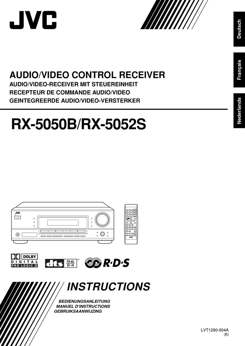
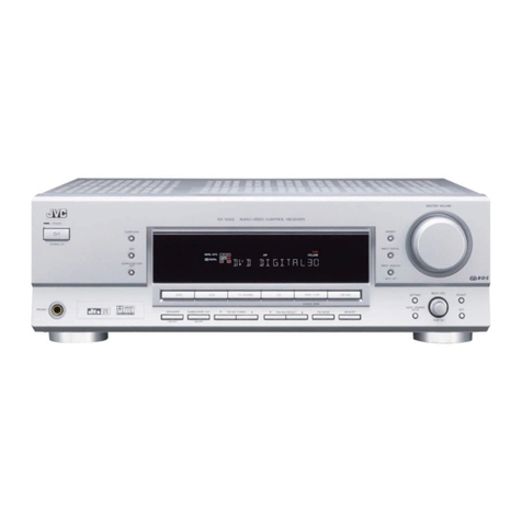
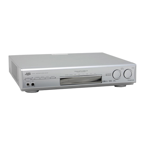
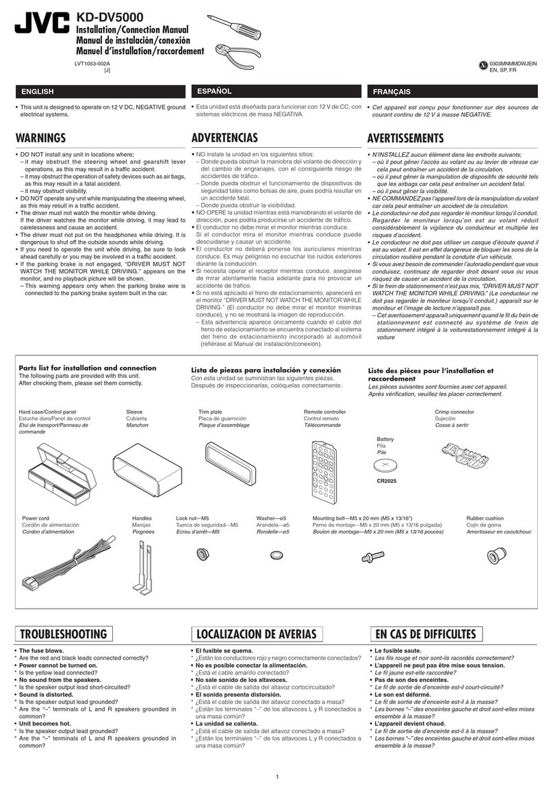
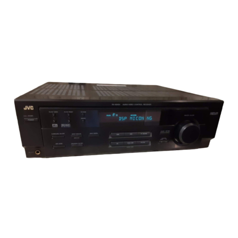
JVC RX-206BK User manual

.rt
r+
6r*f,
-- l-F'rl
Rx-207rN/E&egggK ??rttdt t rNU
rbrytttry t tttl
M
CqnlrrolCaz
rqrnil
E30580-1791
A
(J)
ForCustomer
Use:
Enter
belowtheModel
No.andSerialNo.
which
are
located
eitherontherear,
bot-
tom
orside
ofthecabinet.Retainthisin-
formationfor futurereference.
Model
No.
t4g.*aa 6
SerialNo.
.IYE
F
:
@
4
tgt]
I I r! l-'rl
E_!!l
RX-307TN/RX-3068K

WARNING:
TO REDUCE
THE RISKOF
F|REOR ELECTRTC
SHOCK DO NOT
EXPOSE
THIS
AP,PLIANCETORAIN
OR
MOISTURE.
ntsK
0ttttclRrc
sHocx
00
NoloPtN
CAUTION: TO REDUCETHe RISK
OF ELECTRICSHOCK,
DO NOT
REMOVE
COVERIORBACKI,
NO US€R.S€RVICEABLE
PARTSINSIOE.
REF€RSERVICING
TO
OUALIFIEO
SERVICE
P€RSONN€L,
The lightning
f
lashwirh arrowhead
symbol,
within anequilateral
triangle,
isinterdedto
alertthe userto theDresence
of uninsulated
"dangerous
voltage" within the product's
enclosurethat may be of sufficient
magni-
tude to constitutearisk
of electric
shockto
persons.
The
exclamation
point
within
anequilateral
triangleis intended
to alertthe user
to the
presence
of important operatingand main-
tenance
{servicing}
instructionsin the lrtera-
tureaccompanying
the
appliance.
Page2 to
Contents
3 lntroductlon
3 lnstallatlon Prepantlon
4 Compu LInk Bemote Control System
5 Stereo Component Connectlons
Turntable
Compact
DiscPlayer
TapeDeck
Second
TaoeDeck
VCR
orTV
Speaker Connecilons
Speaker.Terminals
Speakers
1
Soeakers
2
6 AC Power Connactlons
7 AM and F*l Antenna Connecflons
AMLoopAntenna
AMOutdoorAntenna
FM75-OhmAntenna
Cable
FM
300-OhmAntennaCable
8 Front Panel Controls
9 Basfc Operatlon
Llctenlng to Badlo Broadcasts
SelectinganAMorFMStation
Presetting
anAMorFMStation
Uslng Auto-Memory
Auto-Memory
Using
Numeric
Keys
Becordlng lapes
Three-Head
TapeDecks
12 Playlng Back wlth a Sunound-sound Eflect
13 Uslng the Hemote Control
lnsertlng Batteiles
froubleehooting
Specificatlons
10
tl
12
tc
tc

,IYE
-a
E:
@
.r4-
rgF
OO .CI
RX-207TN/RX-2068K
Introduction
a
a
Thank
you
for
purchasing
thlsJVC
Receiver.
Wehopeitwill
bea valuedadditiontoyour
stereosystem.Be
sureto read
theseinstructions
carefullybeforeoperatingthereceiver.This
manual
givesyou
thebasicinformation
you
needto
setup
anduse
your
receiver.ltexplainseverything
you
need
to
knowfromturning
on
the
power
switchtobasictroubleshoot-
ing.
Please
consult
your
JVCdealer
if
you
haveany
questions
aboutthereceiver.
Usethis manualto help
youwlththefollowing:
Connect
your
otherstereocomponentstothereceiver.
Learn
the
functions
ofthecontrolsandindicators
onthe
recerver.
Presetradio
stations
into
thereceiver'smemorv.
Operatethereceiver.
Troubleshoot,if
thereisa oroblem
withthereceiver.
Thismanualis organizedasfollows:
Thefirst
part
ofthis
manual
tells
you
howtoconnect
your
otherstereocomponents
andantennastothe
receiver;
Thesecond
part
ofthismanualintroduces
you
tothecontrols
and
indicators
onthereceiver.
The
third
part
ofthis
manual
tells
you
howtooperate
the
recetver.
The
fourth
part
of
this
manual
provldes
atroubleshooting
guide
andspecificationsforthereceiver.
Usethefollowing
guidelines
to help
youfollowthe
instructions
inthismanual:
Keys
orbuttonstobe
pressed
are
indicatedwith
capitalletters,
for
example:TUNING
key.
Connection
points
onthe
backofthereceiverareindicated
with
allcapital
letters,
forexample:PHONO
Names
ofindicators
thatlight
uponthereceiverare
indicated
with
allcapitalletters,for
example:TUNED
Steps
that
you
needtofollowtoget
thecorrectresults,are
labeledlmportant!
Additional
information
thatishelpfultoknow,islabeledfVote:
a
a
a
RX-307TN/RX-3068K
Installation Preparation
Locatlng the Becelver
Install
thereceiverin a place
that
islevel
and protected
from
moisture.
Thetemperature
aroundthe receiver
must
be between
23o
and'104o
Fahrenheit
(-50 and40oCelsius).
Makesurethereisgoodventilationaroundthe receiver.Poor
ventilation
couldcauseover-heatinganddamage
thereceiver.
Thereceivercouldcausesome
interference
withtelevision
reception.
Locatethe receiveraway
fromyourTV
to prevent
interference.
Maklng Power Gonnectlons
Donothandle
theoowercord
with
wet
hands.
Donot
pull
onthe
power
cordtounplugthereceiver.
Always
pull
the
molded
plug
attheendofthecord
instead.
llandllng the Becelver
Do notinsert
anymetallicobject
into
thereceiver.
Gautlon: To reduce rlsks, such as electilc
shocks or flres:
l. Do not temove scrows, Govets,or cablnet.
2. Donot expose thls appllance to raln or
molsture.
6 | ,UD$.) ,0D. il j ffi | 'es!$
Page3

Compu Link Remote Control System
TheRX-207TN/RX-2068Khas
COMPULINK-1SYNCHRO
terminals
and
theRX-307TN/RX-306BKhas
COMPU
LINK-3
SYNCHROterminals.JVC'sexclusiveComou
LinkRemote
ControlSystemconnectsequipment
with
JVCCOMPULINK-1
orCOMPU
LINK-3
SYNCHROterminalstotheremote
control
system.Youcancontrol
equipment
fromthe remotecontrol
unit,oryou
canuseotherfunctionssuchasautomaticsource
selectionand synchronizedrecording.
Equlpment remote control
Byconnectingthe
COMPU
LINK-1orCOMPULINK-3
SYNCHROterminaltothereceiver,theequipmentthatdoes
not
haveREMOTE
SENSORinits
mainunitcanbe remote
controlledviaREMOTESENSORofthereceiver.
Automatlc aource aetectlon
Pressing
SOURCESELECTkeys
willautomatically
put
thecor-
respondingsourceequipmentintothePLAYmode.When
you
press
the
PLAY
keyonsourceequipment,thecorresponding
SourceSelect
keyis
automatically
settothat
source.Other
sourceequipmentshutsdownabout5 seconds
later.
Note:Automaticsourceselectiondoesnotfunctionona tape
deckconnectedtotheTAPE2/VIDEOSOUNDterminals.
Thisisapplicableonlywithcomponentsthatarecompatible
with
JVC'sCompu
LinkRemote
Control
System.
Synchronlzad recordlng
With
synchronized
recording,
atape
deckcanstart
recording
automaticallywitha CD
player
orturntable.
Note:
Read
your
tapedeckmanualformaore
information
on
synchronized
recording.
Thisisapplicableonlywith
components
thatarecompatible
with
JVC'sComouLinkRemoteControlSvstem.
CD auto-changer wlth COHPU LtNK-g SYNCTIBO
tetmlnal
You
can
turnon/off
theCDauto-changeralong
withthe
RX-307TNiRX-3068K
byconnectingtheCOMPU
LINK-3
SYNCHROterminaloftheCDauto-changertothe
RX-307TN/RX-306BK.
Fordetails,
refer
totheCD
Auto-
Changer
Instructions.
How to Connect Compu Link
This
diagram
showshow
Compu
Link
compatible
components
areconnectedtotheCOMPU
LINK-1
orCOMPU
LINK-3
SYNCHROterminals.
CD
Player TapeDeck
Important! Do not connectthe remotecable whenconnect-
ing theJVC cassettedeck havingCOMPULINK-I/SYNCHRO
terminalsto the TAPE2/VIDEOSOUNDterminals,
Page4

Stereo Component Connections
You
canconnectthefollowing
stereocomponentstotheback
ofyour
receiver:
r Turntable
. CompactDiscPlayer
. TapeDeck(s)
r VCR
orTV
The
followinginstructionswill
show
you
how
toconnectstereo
componentstothereceiver.
lmporbnt! Makesure
youconnecttheleftchannelsofall
stereo
componentsto theleft
jackson thetoprowof the
receiver.
Connect
therightchannelsofallstereocomponents
to therightjacks
onthebottomrow of thereceiver.lf you
reversethechannels,
thestereosoundwillbe affected.
Turntable
Q Connect
the
left
andrightchannels
on
your
turntabletothe
left
andright
jacks
markedPHONO
on
the
backofthe
receiver.
lmpoftant! Usethereceiver
onlywithturntables
thathave
a
moing magnetic
(MM)
typecartridge.
Compact DIsc Player
O Connecttheleft
andrightchannelson
your
compactdisc
player
totheleft
and
right
jacks
marked
CDon
theback
of
thereceiver.
fape Deck
O Connecttheleftandright
"Line
In"channels
(acks
marked
REC)
onyour
tape
decktotheleft
andrightTAPE1jacks
markedOUT
(REC)
onthebackofthereceiver.
@Connectthe
left
andright
"Line
Out"channels
(acks
marked
PLAY)
onthetapedecktothe
left
andright
TAPE1jacks
marked
lN
(PLA[ onthebackofthereceiver.
Second lape Deck
€)Connect
theleft
andright
"Line
In"channels
(acks
marked
REC)
on
your
secondtape
decktotheleft
and
right
TAPE
2nlIDEO
SOUND
jacks
marked
OUT
(REC)
onthebackof
thereceiver.
@Connect
theleft
andright
"Line
Out"channels
(acks
marked
PLAY)
ofthe
tapedecktotheleft
andrightTAPE
2//IDEO
SOUND
lacks
markedlN(PLAY)
onthebackofthereceiver.
VCB or TV
{DConnecttheleft
andrightaudioinput
channelson
your
VCR
orTV
totheleft
andrightTAPE2llIDEO
SOUND
jacks
marked
OUT
(REC)
onthe
backofthereceiver.
@
Connecttheleft
andrightaudio
outputchannels
on
your
VCR
orTV
totheleft
and
right
TAPE2llIDEO
SOUND
jacks
marked
lN(PLAY)
ontheback
ofthereceiver.
Page5

r
I
iSpeaker Connections
;WW You
canconnecttwopairs
ofspeakers
(four
speakerstotal)to
thisreceiver.Thetwopairs
ofspeakersarecalledSpeakers
1
andSpeakers
2.
Important!Besureto match
thepolarity
of thespeakerterm|
nalswiththepolarity
of theterminals
onthereceiver.
(+) to
(+) and
(-) to(-).
Note: This
receiver
is onlyforusewith
speakers
havingim-
pedance
of 8 to 16ohms.
Check
yourspeakerspecifications
tomake
surethe speakers
havethecorrect
impedance.
Speaker fermlnals
O Wnen
connectingspeakers,openeachterminaland
insert
the
endofthespeakerwireasshown.
€) Ctose
the
terminalsasshowntoclampthespeaker
wiresin
prace.
Speakers I
Connect
thefirst
pair
ofspeakers
(Speakers
1)tothereceiver
as
follows:
@Connect
the
(+) and
(-) terminalsoftheright-sideSpeaker
1
to
the
top
(+) and
(-) terminalsmarkedRIGHTonthe
receiver.
@
Connectthe
(+) and
(-) terminalsofthe
left-side
Speaker
1
tothetop
(+) and
(-) terminalsmarkedLEFTonthe
receiver.
Speakets 2
lfa second
pair
ofspeakers
(Speakers
2)isto beused,
connectthemtothereceiveras
follows.
@Connect
the
(+) and
(-) terminalsofthe
right-sideSpeaker2
tothebottom
(+) and
(-) terminalsmarked
RIGHT
onthe
ranoirror
@Connectthe
(+) and
(-) terminalsoftheleft-sideSpeaker2
tothebottom
(+) and
(-) terminals
markedLEFT
on
the
receiver.
@
o
Soeakers1
left right
--
-IE
--rr--
IIEIIE
t-.---r
rn,--:nr
rl!- -[rr
LU--.-r
E-. --.-
-
EH
t//-U z/zGfl
fTrrn\t tTFrtYt
II||[ f,tr I.tE lta
vv
oo
Speakers2
left right
B
o
o0
AC Powet Connectlons
tmpot|anil Before
youplug thepower
cordintoan outlet,
makesureallstereocomponentsareconnectedcorrectly.
Donotconnect
stereo
componentsrequiringmorethan180
watts
(total)
to thereceiver.
Gautlon. lo prevent electrlc.hoclq tum dl rtcrso com-
ponont! otf bclore you Instlll or nemove
power cordl.
Plugthe
power
cord
on
the
back
of
the
receiverintoa 120
volt.60Hz
AChousehold
electricaloutlet.
You
canconnectthepower
cordsoftheotherstereocompo-
nentstothetwoACoutletsonthebackofthereceiver.
Note: <RX-207TN/RX-2068K
>
The
ACoutlets
providepower'whenever
the
receiveris
pluggedin,regardlessof ther*eiver's power
switch
setting.
< RX.3O7TN/RX-3O6BK>
TheAC outletsareconnectedto thereceiver's
ON/STANDBYcircuits.Whenthepowerswitch
is setfo
STANDBY,
power
willnotbesupplied.
Page6

AM and FM Antenna Connections
AM Loop Antenna
75-OhmAntenna
withcodial cable
To receiveradiobroadcasts,
youwillhaveto connectAM and
FMantennasto the receiver.
An AM loopantenna
isincludedwith
yourreceiver.
FMantennasusetwotypesof cableconnections:
75-ohm
cables
have
a round
coaxialconnectionwhile300-ohmcables
have
a flat
connection.
AH Loop Antenna
Q Fold
outtheloop
from
theantennabase.
@Connectoneantenna
wiretooneof
theAMLOOPterminals
onthereceiver.
@Connectthe
remaining
antennawiretotheotherAMLOOP
terminal.
Note:Thesetwoterminals
open
andclose
the
same
wayas
the
speaker
terminals.
O Adjust
the
loop
antennaasneeded
toget
thebestreception.
AM Outdoor Antenna
lfyour
AMbroadcastreception
isunsatisfactory,
you
should
connectan
AM
outdoorantenna
in
addition
tothe
looo
antenna.
lmportant!The
AMloop
antenna
must
beinstalledtoreceive
AMbroadcasts.
Donotdisconnect
theloopantennawhen
installing
anoutdoorantenna.
Q Install
a single
vinyl-covered
antenna
wire
outdoors.
Thean-
tennawiresholdbeabout16to40feet
(5
to 12meters)long.
@Connectoneendoftheantenna
totheAMloopterminal
markedAMEXT.
Note:Exceptfortheconnection,
make
sureno uninsulated
antenna
wire
touchesthe
rear
panel
ofthe
receiver.
Otherwise,the
receiver
might
not
pickupAM broadcasts.
F|t 75.Ohm Antenne Cable
Q Loosen
thescrews
holding
thebrackettothe
rear
panel
of
thereceiver.
O Loosenthe
capof
the300/75-ohm
terminalon
therear
panel
ofthereceiver.
@Insert
theroundantennacablethroughthebracketfrom
below.
@Vake
surethattheshieldbraidonthecablecontactsthe
bracket.andthatthe
center
conductor
ofthecablecontacts
the300/75-ohmterminal.
@
lgfrtenthebracketscrewsandthecaponthe300/75-ohm
terminal.
Ft ?OO-Ohm Antenna Cable
Q Loosenthecaponthe300/75-ohmterminalontherear
panel
bfthereceiver.
O Loosenthecaponthe300-ohmterminal
on
therear
panel
of
thereceiver.
@
Connectthetwoconductorsofthe
antennacable
tothe
300/75-ohmterminalandthe300-ohmterminal.
@
Tighten
thecapsonbothterminals.
Note:Whether
youusethe75-ohm
or300-ohmcable,make
suretheantennaconductorsdonottouchanyotherterminals
onthereceiver.Thiscouldcause
poor
reception.
Fl\,4FeederAntenna
Page7

< RX-2O7TV/
RX.2O6BK>
-
-ffi-
<RX.3O7TN/
RX-3O6BK>
l-J,,iffi.
Front Panel Controls
O Power Swltch
Press
thisswitchtoturn
onoowertothe
receiver.Press
the
switchagaintoturn
offthe
power
andactivatethe
STANDBY
mooe.
Note: Thereceiver
usesa smallamountofpower(5 watts)
in
the STANDBYmode.Todisconnect
power
completely,unplug
the
power
cord.
@Speaker Swltch
Press
thetwoSPEAKERSswitches
in
toturnSoeakers1and
Speakers
2 on.
Press
theSPEAKERSswitchesouttoturnthe
speakersoff.
@Headphone.tack
Stereo
headphonesmay
beconnected
here.For
private
listening,
press
bothspeakerswitchesoff.
@ Source $elect
Usethesesixbuttonstochoosethestereosource
you
want
tolisten
to.
SourceIndicator
Lightsshowwhichsource(s)have
beenselected.
PllONOt Presstolistento records.
CD; Presstolisten
toCDs.
FIG Press
to listen
to FMbroadcasts.
Itl Press
tolisten
toAMbroadcasts.
1APE 1., Pressto
use
the
tapedeckconnected
totheTAPE1
jacks
onthereceiver.
TAPE2NTDEO SOUNDTPresstousethetapedeck,
graphic
equalizer,or video
equipmentcon-
nected
tothe
TAPE
2llIDEOSOUND
jacks
onthereceiver.
G)9ource lndlcator Hghts
Theselivelights
tell
you
whichstereosource(s)are
being
played
throughthereceiver.TheTAPE
2 MONITOR
indicaior
mayturnon
oroff
independently
whileotherindicators
are
@ Surround Indlcator Llghts
Thisindicatorlights
upwhen
the
surroundsWitch
isON.
O Tuner DIspIay Wlndow
TheTunerDisplayWindowindicators
provide
informationon
AM
and
FM
broadcast
reception.
TheTunerDisplayWindow
isalsousedto setandrecalloreset
radio
stations.
Page
8
O <RX-2o7TN/RX-2o6BK>
BECE YED Indlcator
This
indicatorlightsupwhensignalsarereceivedfromthe
remote
controlunit.
<RX.3O7TN/RX.3O6BK>
BECEMD and POWER 9IANDBY lndlcator
Thisindicatorlights
upwhensignalsare
receivedfromthe
remote
controlunitorwhen
thereceiverisinthe
STANDBY
mode.
9Remote Sensor
TheRemoteSensorreceivesthesignalsentby
theremote
controlunit.
Note:lt is important
to keeptheRemote
Sensor
clearof
obstructionsin orderforit to receive
signals
fromtheremote
controlunit.
@Bass Control
Thiscontrolsthe
low-frequency
sound
range.TurntheBASS
control
rightto boost
bassresponse.Turn
leftto decrease
' bass.
@ trcble Control
Thiscontrolsthehigh-frequencysound
range.Turnthe
TREBLE
control
right
toboosttreble
response.
Turnleft
to
decreasetreble.
@?alance Control
Thiscontrolsthevolume
balancebetweenthe
left
andright
speakers.TurntheBALANCE
controlrighttoincrease
volume
fortheright
speaker(s).
Turn
theBALANCEcontrolleftto
increasevolumefor
the
left
speake(s).lnthecenter
position,
left
and
right
speakershave
equal
volume.
@Volume Control and Yolume lndlcator Hght
Turn
theVOLUMEcontroltoadjust
the
volume.
The
VOLUME
indicatorlights
upwhenthe
power
isONandfickerswhen
theremotecontrolisused
forVOLUME
and
FADE
MUTING.
@funer
Usethebuttonsonthetunertotune
in
the
AM
orFM
broad-
caststation
you
wantto listento.These
buttonsarealsoused
forsettingandrecalling
preset
radiostations.
@9unound Swltch
This
switchturnsthe
surroundsoundeffectONorOFF.
< RX-2O7TN/
RX.2O6BK>
I
-<RX3O7TN/
RX.3O6BK>
ME
I

I
I
I
Basic Operation
O To
turn
on
your
receiver,
press
thePOWER
switch
on.
The
Tuner
Display
Window
lights
up.
The
Sourceindicator
Lights
show
thesource
that
waslast
played.
JVE
[J
"o
Q)
Select
thespeaker
system
you
want
by
SPEAKERS
1switch,
the
SpEAKERS
2
switches.
Note:lf just
onepairof speakers
is connected
to thereceiver
and
you press
bothSPEAKERS
switches,
nosound
will
be
heard.
O tt
you
want
tolisten
through
headphones,plug
them
intothe
Headphones
Jack.
Note:
lfyoudo notwant
sound
coming
through
thespeakers,
press
bothSPEAKERS
switches
off.
@Press
one
ofthe
Source
Select
buttons
tochoose
the
stereo
source
you
want
tolisten
to.
The
corresponding
Source
Indicator
Light
shows
which
stereo
source
isbeing
played.
Note:Operate
thestereosources
(forexample:
CD,phono,
tapedeck)
by following
theappropriate
instruction
manuals.
() Turn
theVOLUME
controltoadjustthe
volume.
Impoftant! Listening
toan ertremely
loudsoundmay cause
a hearing
defect.Adjust
thevolume
properly.
Especialty
when
using
headphones,
avoid
listening
toan ertremelyloud
sound.
@turntheBALANCE
control
left
orright
toset
the
balance
between
the
left
andright
speakers.
@Turn
theTREBLE
controlleft
orrighttodecrease
orIncrease
treble
(high
frequency)
soundlevel.
@Turn
theBASS
control
left
orright
todecrease
orincrease
bass
(low
frequency)
sound
level.
E
pressing
the
switch,
orboth
Page9

Listening to Radio Broadcasts
. t;:l
-- I t----1 |
L*lll
ffi
Selecting an AM or FM Station
O Turn
the
receiver
on
@ Press
the
AM or FM
SourceSelectbutton.
. lfyoupressed
theAM SourceSelectbutton,
AM and
kHz
appear
inthe
Tuner
Display
Window.Thereceiver
tunes
in
the
lastAM frequency
thatwas
played
lfyoupressed
theFMSourceSelectbutton,FMandMHz
appearinthe
Tuner
DisplayWindow.Therecervertunesin
thelastFMfrequency
thatwas
played.
O Use
theTUNINGkey
tofind
the
radiofrequency
you
wantto
listen
to.Presstherightsideofthekeytofindhigherfrequen-
cies;
press
theleft
sideofthekeytofind
lower
frequencies.
When
yourelease
the
TUNINGkey,
the
receiver
auto{unes
until
it
tunesa stationin.Youcanstopauto{uning
by press-
Ing
any
tuner
button.
TheTUNEDlndicator
lightswhenthereceiveris
tuned
oreciselv
to eitheranAM or FMstation.
Note: Tapthe TUNING
keymomentarilytochange
thefre-
quency
tn steps
of 10kHzfor
AM and0.1MHzforFM.
Hold
the TUNINGkeydownto changethefrequencyfaster,
then
tAn thq ko\/ tn cpt lho froar tanav nroaicaltt
lmportant! lf thereceiveris tunedtoa statton
but the TUNED
lndicatordoesn'tlight, try adjustingthe antenna
for better
reception.
When
you
tunetoan FMstation,thereceiver
automatically
plays
instereo;the
STEREOindicatorandtheAUTOindicator
arelighted.
@ Press
the
FM
MODE/MUTEbutton
whenlisteningtoanFM
station
with
a weakor noisysignal.Receptionwil be
improved,although
you
willbe
listening
to
monaural
(non-
stereo)sound.
TheSTEREO
indicator
andthe
AUTOindicator
disaooear.
Presetting an AM or FM Station
Vnrrnan ^rocar . tntSl
gf 40 radiOStatiOnS
intO
the reCeiver'S
memory.
You
preset
a stationbyassigning
it
a channel
number
(1
to40) Oncea station
has
been
preset,you
can
tunetothatstationusingtheNumerickeysratherthanthe
TUNINGkey.
(See UsingNumerrcKeys
' onpage
1
1.)
Q Turn
the
receiver
on.
@ PresstheAM ortheFM
SourceSelect
button,
O UsetheTUNINGkeytotune
in
theradiostation
you
wantto
Dreset.
@ Press
theMEMORYbutton.
TheMEMORYindicatorlights
and- - CHappears
(- -
blinks)
in
theTunerDisplayWindowforabout
five
seconds.
@ UsingtheNumerickeys,enterthechannel
number
(1
to
a0)
you
want
to assrgntothestatron.
ThechannelnumberappearsintheTunerDisplayWindow.
lmportant! Youmust
enter
thechannelnumberwhilethe
MEMORY
indrcator
is lighted.lf the indicator
turnsoff too
soon,press
theMEMORYbuttonandstartagain.
Repeat
theabove
process
to preset
additional
radio
stations.
Note: Preset
stattonsare held in the receiver'smemoryas
long as the receiver
is plugged in. lf the receiveris un-
plugged, or if a power fatlure
occurs,the receiverwillkeep
thepresetsfor two or threedays beforeerasrng
them.
P2^a 1n
Using Auto-Memory
Auto-Memory
TheAuto-Memoryfunctionlets
you
scana serresofradio
stations,and
preset
the
ones
you
want
intothereceiver's
memory.Thereceiverwillscan
radiofrequenciesand
preset
thestations,astheyare
tuned,withascendingchannel
numbers.
(O
Turnthe
receiver
on.
@PresstheAMortheFMSourceSelectbutton.
G)
Use
theTUNINGkeyto
find
the
lowestfrequency
you
want
to
startscanning
from.
@Press
the
AUTOMEMORYbutton.
TheMEMORYindicator
lights
and
- - CHappears
(- -
blinks)
intheTunerDisplayWindow
for
about
five
seconds.
@ UsingtheNumeric
keys,
enter
the
lowest
channel
number
(1to 40)you wantto assign
a preset.
lmportant! Youmust enterthechannelnumber whilethe
MEMORYindicator is lighted. lf the indicator turns off too
soon, press
theAUTO MEMORYbuttonand startagain.
Whena radiostation
is
tuned
in,
scanning
stops.
The
TUNED
indicator
lights,
andthe
first
preset
channel
number
and
the
frequency
ofthestationtunedinaredisplayedalternately
for
about
five
seconds.
Whenthisstation
ispreset,
scanning
startsagain.
@ lf youdo notwantto preset
that
station,
press
theAUTO
MEMORYbutton
whilethechannel
numberand
frequency
aredisplayed
alternately.Thereceiverwillstart
scanning
again.
This
process
continuesautomatically
untilall
40channels
are
filledortheupper
frequency
limitisreached.
Uslng Numerlc Keys
Presetstationsareset
intothereceiver's
memoryand
recalled
usingthe
Numerickeys.
Toindicate
numbers1to 10,
press
theappropriate
key.To
indicatenumbers
11
to
40,
you
needtouse
the+
10key
and
oneother
key.Seethe
followingexamples:
Toindicate17:
press
the+10key,
thenthe
7 key.
Toindicate20:
press
the+10key,thenthe
10key.
Toindicate25:
press
the+10keytwice,
thenthe5 key.
Toindicate40:
press
the+
10keythreetimes,
thenthe
10key.
Page
11

Hecording Tapes
lfyou
haveatape
deckconnected
totheTAPE1orTAPE
2^/IDEOSOUND
jacks
of
thereceiver,
you
canrecordother
stereosourcesontoataoe.
(OTurn
thereceiveron,
@PresstheSourceSelectbuttonforthesource
you
wantto
recordfrom.
Note:WhenrecordingfromTAPE2 to TAPE1,press
the
TAPE2/VIDEOSOUNDbuttonandanotherbuttonotherthan
TAPE1.
. Usethetapedecktorecordthesourceasitisplaying.
Follow
theinstructionsfor
your
tapedeck,
Note:Adjusting
theVOLUME
controlofthereceiverwillnot
affecttherecordinglevel.Followtheinstructions
foryourtape
deck.
Three.llead 7ape Decks
lfyou
have
athree-head
tapedeck,
you
canuse
it
tomonitor
the
soundbeingrecorded.
Connect
thetapedecktothe
TAPE2llIDEO
SOUND
jacks
ofthereceiverand
proceed
as
follows:
. Start
recording
thesourceontothe
TAPE
2 deck.
WhentheTAPE2 MONITOR
IndicatorLightisoff,
you
hear
thesound
of
thesource
playing
throughthespeakers.
PresstheTAPE2/VIDEO
SOUNDbutton.TheTAPE2
MONITORlndicator
Lightwilllight.Now
you
hearthe
sound
of
therecordingimmediately
as
itismade
on
thetape.
By
pressing
the
TAPE
2llIDEOSOUND
buttononandoff,
you
cancomparethesound
quality
ofthesourcewiththe
quality
ofthetaperecordingbeingmade.
Playing Back with a Surround-sound
Etfect
PlayingbackastereosourcewiththeSURROUND
keyON
will
produce
asurroundingsoundeffect.
@Connectspeakersystems
tothe
SPEAKERS
1and2
terminals.
Note:A singlespeakersystem
canproduce
a surrounding
soundeffectby itself,
buttheuseof twospeakersysfems
is
recommended
fora moreidealsurroundingsoundeffect.
@turnthe
receiver
on.
O Turn
ONtheSPEAKERSswitches,
1 and
2.
O Press
theSURROUND
key.
@Play
backthestereosource.
lfa speakersystemwitha low-rated
input
is
connected
to
SPEAKERS
2,
avoidusing
itindependentofSPEAKERS
1,
and
pay
attentiontoitsVOLUME
controlduring
surrounding
sound
playback.
Monauralsourcecannotbe
played
back
withthe
surround
soundeffect.
itffi
SPEIIGRS
un
Page
12

Using the Bemote Control
Aim the signals at the REMOTESENSOR
<RM-SR2O7U>
for
RX-2O7TN/RX-2068K
on the receiver.
< RM-SR3O7U
>
for RX'307TN/RX-3068K
.fYE **,0,1**Sil'ffi[
H3 14
EE]
>Pc
trl cl
EE
E] EF
FADEruTIIS - VOLUT'E+
PHOT€ CO TAPE I
CfEE
FT' AM
>t a42 tst3 a1
CfEEE
ll 5 <6 >P .
EE EE
- rxE5E I i
EE
vc? TAPE I CO oISC
"fYE **,'L*Si€'SIil&
Cf EE
FADEI'I.JTING -VOLI.JI.IE+
SOURCESELECTkeys
SelectableFunctionkeys
CONTROLSection
Theremote
controlunit
provided
control
thereceiverand
JVC'saudio
visual
gear
from
a remote
place
viathe
Compu
LinkRemote
ControlSystem.
Direct
thetransmitterwindowoftheremotecontrolunitat
targetequipmentwithina distanceof7 meters.
Take
careto
avoidobstaclesbetweenthetransmitterand
thetarget.Press
keys
slowly
and
positively,
makingsurethedesired
functions
result.
The
keymarkingsonthetransmittermay
notmatchthose
on
theequipment.Checkthemarkings.
Theremotecontrolunit
cannot
control
equipment
functions
they
donot
support.Olderequipmentmaynotbereceptive
to
theirinput.
Check
for
connectionof
the
COMPULINK-1orCOMPU
LINK-3
SYNCHROterminalsontheremoteequipmentbya
remote
cable.
Switch
on
the
power
toalltheequipmentrequiredbefore
startingoperation.
When
operatingtheVCRbyRM-SR307U,iftheVCRhasa
raemotecontrolcodeswitch,settheswitchto "A" mode.
O POWER (RM-SR307U
only)
AUDIO: Presstochange
thepower
forthereceiverONor
STANDBY.
' VCR: Press
toturnonorofftheoower
toJVC'sVCR.
TV: Press
toturnonoroff
the
oowertoJVC's
W receiver.
€)VOLUME
(-, +)
Presstoadjusttheoutputsound
level.
FADEMUTING
Presstodecreasetheoutputsound
level
gradually.
Page13

Operatingthesourceequipment
FM/AMbroadcast
1 . Pr"r. the
FM
orAMkeyofthe
SOURCE
SELECTkeys.
2. Ur" theSelectable
Function
keys.
PRESET
+ :Scanstohigher
preset
channels.
- :Scansto
lower
oresetchannels.
Turntable
1 . Pr"r.thePHONOkey
oftheSOURCESELECTkeys.
2. U." theSelectable
Function
kevs.
r :Stop
play.
CDPlayer
1 . Pr".,theCDkeyofthe
SOURCE
SELECTr<eys.
2. U." theSelectableFunctionkeys.
I :Stopsoperation.
11< :Skipstothebeginningofthe
previous
track.
)1't :Skipstothebeginningofthenexttrack,
<< : Movesbackward
quickly
during
play.
>> : Movesforward
quickly
during
play,
1 :Stops
play
temporarily.Toreleaseit,
press
)
CDAuto-changer
1 . Pr"..the
CD
DISCkey
oftheCONTROLSectionkeys.
2. U.. theSelectableFunctionkeys.
1-5, P: Selectthediscnumber.
3. Pr".,the
CD
keyof
theSOURCESELECT
xeys.
4. U." theSelectableFunctionkevs.
Starts
play.
Stopsoperation.
Skipstothe
beginningof
the
previous
track.
Skipstothe
beginningofthe
next
track.
Movesbackward
quickly
during
play.
Movesforward
quickly
during
play.
Stops
play
temporarily.Toreleaseit,
press
)
TapeDeck
(TAPE
1)
1 . Pr".,theTAPE1kev
of
the
SOURCESELECT
or
CONTROL
Section
keys.
2. U." the
Selectable
Functionkeys.
r :Stopsoperation.
r<< :Skipstothebeginningofthe
previous
tune.
>rr :Skipstothebeginningofthe
next
tune.
u : Stops
playback/recording
temporarily.
Toreleaseit,
press
) .
<< : Fastwindsthetapefromrighttoleft.
p : Fastwindsthetapefromlefttoright.
c : Presstogetherwith
) tostartrecording.
Presstogetherwith
lt toenterrecord-pause
mode.
. UseCONfROLSectionkeys
(VCR
orTAPE
1)to
operatean
equipment
while
you
are
listeningto
thesoundofanother
source,
for
example,tohave
atapedeckstandby
while
playing
aCD.
TapeDeck(TAPE
2)
1 . Pr"r,theTAPE2 keyottheSOURCE
SELECT
keys.
2. nt^p"deck
connectedto
theTAPE2/VIDEO
SOUNDterminal
cannot
be
operated
withtheremote
controlunit.Use
the
switches
orbuttonsontheapparatus.
VCR
(RM-SR307U
only)
o Aim
thesignalsdirectlyatthe
VCR.
a| . Pressthe
VCR
keyoftheCONTROL
Section
Keys.
2. U.. theSelectableFunctionkeys,
I : Stopsoperation.
1 : Stops
playbacl</recording
temporarilyandenters
thepause/still
mode.To release
it,press
) .
<< : Rewinds
videotape.
>> : Fast-forwards
videotape.
. : Press
together
with ) to start
recording.
Presstogetherwith n to enterrecord-standby
mooe.
t
K<
>x
<<
)}
tl
Page
14

1.
Inserting Battefies
Batteriee
TheRemoteControl
unituses
two (2)
AAA size
(UM-4,
R03
1.5V)
batteries.
Theuseoflong-life
drycells
isrecommended.
Battery Beplacement
lfthe rangeofthe remoteseemsshortened,the batteriesmay
beold.
Tryreplacing
theoldbatteries.
lmportant! Do not usea new batterywithan old battery.
Usebatteriesofthesamebrand.
Batteries
canvaryin voltage
eventhoughthey
look
alike.
lf youarenotplanning
to usethe remotecontrolfor an
extended
period
oftime,removethe batteries.
Cauilont Do not heat batteilea or attempt to dlspose
of them by bumlng.
Removethe rearcover
ofthe remotecontrolunitby pressing
down
gently
while
sliding
it
out.
lnsertthebatteries,makingsurethattheir
position
matches
thatofthediaoraminsidetheremote.
3. Replace
the
rear
cover
2.
Troubleshooting
Problem
Receiver
does
not
play;
Indicators
do not
lightup.
Nosoundfromthe
^^ ^ ^t. ^-^
PosslbleCauee Solutions
Powercordnot
plugged
in. Plug
Powercordinto
anAC outlet.
Speaker
wiresnot
connected
properly. Checkspeaker
wiring
Reconnect
ifneeded.
SpeakerButtons
not PresstheSpeaker
set
correctly. Buttons
in or outas
desired.
Sound
fromone
speaKeronry. Speakerwires
not
connected
properly. Checkspeaker
wiring
Reconnect
if needed.
BalanceControlmay SlideBalanceControl
beset
toone soboth
speakers
extreme. havesound.
Continuoushissor
buzzingduring
FM
reception.
Incomingsignalmay Adjustantenna.
betooweak.
Station
maybetoofar
away
to receive.
Incorrectantenna
used. Checkwith
your
deal-
erto makesure
you
areusingthecorrect
typeof antenna.
Antennanot
connected
properly. Makesureall
anrennasarepropeny
connected.
Occasional
cracking
noise
during
FM
reception.
lgnitionnoisefrom
automobiles. Movetheantenna
furtheraway
from
the
road.
Loud
hum
during
record
playing. Turntablenot Check
theturntable
connected
properly. manual.Groundthe
turntableifreouired,
lnterference
from
otherelectrical
applrances.
Trymovingthe
power
cordor plugging
into
a differentoutlet.
Howlingduringrecord
playrng. Turntabletoocloseto
a speaKer. Move
speakersaway
fromtheturntable.
Page15

RX-207TN/RX-2068K
40 watts
per
channel,min.RMS,
both
channelsdriven
lnto
8 ohmsfrom40 Hz
to
20 k1z, withno more
than0.080/ototal
harmonic
distortion.
0.080/o
at 40 watts
2.5mV/47k
ohms
200mV/47kohms
200mV
20NzIo20kHz
+ 1dB
70dB
('66
rHF),78dB
(',78
rHF
RECOUT)
91dB
('66
rHF),
80dB
(',78
tHF)
87.5MHz
to
108.0
MHz
Mono:10.8
dBf
(0.95p
V/75ohms)
Mono:16.3
dBf
(1,8p
V/75ohms)
Stereo:38.3dBf
(22.5p
V/75ohms)
Mono:
80dB
Stereo:
73 dB
Mono:0.150/o
Stereo:0.20lo
30
Hz
to
15
kHz,+0.5dB,
-3 dB
1.5
dB
60dB, +400kHz
85dB (at
98 MHz)
40 dB (at1 kHz)
530kHzto
1,710
kHz
30pV. (external)
300pV/m. (loop
antenna)
50dB (100mV/m)
25dB
(t 10kHz)
AC12OV'v,
60Hz
120watts,150VA
17-3116x5 x 13inches
(435
x 126x330mm)
14.8lbs.
(6.7
kg)
Specific
ations
Power
Requirements
Power
Consumption
Dimensions
(WidthxHeightxDepth)
Weight
RX-307TN/RX-3068K
80watts
per
channel,min.RMS,both
channels
driven
into
8 ohms
from40 Hz
to
20 kHz,
withno more
than0.030/ototal
harmonic
distortion.
0.030/oat 80 watts
2.5mV/47kohms
200mV/47k
ohms
200mV
20Hzto20kHz
+1dB
70dB
('66
IHF),
78dB
('78
rHFRECOUT)
eldB ('66
rHF),80dB
('78
rHF)
87.5MHzto 108.0
MHz
Mono:10.8
dBf
(0.95p
V/75ohms)
Mono:16.3
dBf
(1.8p
V/75ohms)
Stereo:38.3dBf
(22.5p
V/75ohms)
Mono:80
dB
Stereo:
73dB
Mono:0.150/o
Stereo:0.20lo
30Hzto15kHz,+0.5dB,
-3 dB
1.5
dB
60
dB, +400kHz
85 dB (at
98 MHz)
40 dB (at1 kHz)
530kHzto 1,710kHz
30p
V. (external)
300pV/m. (loop
antenna)
50dB (100mV/m)
25dB(t 10kHz)
AC
120V'v,
60Hz
190
watts,,
260VA
17-3116
x 5 x 13inches
(435
x 126x330mm)
18.3lbs
(8.3
ks)
i
-Measured
at 1,000
kHz.
Design
and specifications
subjectto changewithoutnotice.
JVE
OutputPower
(CD
inSpeakersout)
Intermodulation
Distortion
Input
Sensitivity/lmpedance
PHONO
TAPE1 PLAY,
TAPE2 PLAY,
CD
Recording
OutputLevel
Frequency
Response
CD,TAPE1,
TAPE
2
Signal{o-NoiseRatio
PHONO
CD,
TAPE1,TAPE
2
TuningRange
UsableSensitivity
50dB
Quieting
Sensitivity
Signal{o-NoiseRatio
Total
HarmonicDistortion
(1kHz)
FrequencyResponse
Capture
Ratio
(85dBf)
Alternate
ChannelSelectivity
lFResponseRatio
StereoSeparation
Tuning
Range
Sensitivity
Signallo-NoiseRatio
Selectivity
sIk
F€ EN VICTOR
COTIPANY
OFJAPAN, LIMITED @ tos''*tt
s42rM
This manual suits for next models
3
Table of contents
Other JVC Receiver manuals

JVC
JVC KW-V520BT User manual

JVC
JVC KD-X472BT User manual

JVC
JVC EXAD KW-AVX708 User manual

JVC
JVC UX-G357UT User manual

JVC
JVC KD-X230 User manual

JVC
JVC RX-6020VBK Mounting instructions

JVC
JVC KD-LX330R User manual

JVC
JVC KD-X560BT User manual

JVC
JVC KD-SX985, KD-SX885 User manual

JVC
JVC S890 - KD Radio / CD User manual