COHU 3920HD series User manual

HeliosTM Products
INSTALLATION MANUAL Series
3920HD
3920SD
Dome Positioner System
www.CohuHD.com
July 15, 2014
Technical Manual 6X-1097B

2 6X-1097B
Table of Contents
About this document 3
Additional information and documents related to the Camera 3
Copyright/Intellectual property rights statement 3
FCC compliance 3
Support services 3
Returns 4
Safety instructions 5
1.0 Introduction 6
1.1 Product Description 6
1.2 Equipment Supplied 7
Optional Accessories 7
2.0 Installation 7
2.1 System Cable Requirements 9
Alarm I/O (Future) 10
2.2 18-pin MS Connector and Its Mating System Cable Connector 11
2.3 CohuHD Manufactured System Cables 12
3.0 Mounting Methods 15
3.1 Wall Mount 15
3.2 Pole Mount 16
3.3 Installation Procedures 17
4.0 Quick Check 20
4.1 IP Control and Viewing of Camera 20
4.2 Factory Default IPAddress and Settings. Assigning the new Camera IP Address 20
4.3 Using the Helios CohuONVIFDiscovery Software to Discover the Camera 21
4.4 Checkout Procedure 21
5.0 Maintenance 22
5.1 Housing Pressurization 22
5.1.1 Schrader Valve 22
5.1.2 Pressure Relief Valve 22
5.1.3 Pressurizing Procedure 23
6.0 Warranty 23

3
6X-1097B
About this document
This manual contains information on the installation and maintenance of the 3920HD/3920SD dome camera
systems. Please read this manual carefully prior to installation to prevent any accidental damage or misuse.
The manual is available from the CohuHD website at
• 3920HD at www.CohuHD.com/products/3920hd.html
• 3920SD at www.CohuHD.com/products/3920sd.html
The information in this manual is subject to change without notice. Please refer to the above website for
the latest information.
Additional information and documents related to the Camera
Forinformationonthecamerasystemoperationandconguration,pleaseseeOperationmanual6x-1090.
ThemanualisavailablefromtheCohuHDwebsitelistedaboveonspecicproductpagesunderthedown-
loads tab.
Copyright/Intellectual property rights statement
Copyright2014byCohuHDCostar,LLC.CohuHDCostar,LLChasintellectualpropertyrightstotechnology
embodied in the product described in this manual.
CohuHD™andHelios™aretrademarksofCohuHDCostar,LLC.
FCC compliance
This equipment has been tested and found to comply with the limits for a Class A digital device pursuant
to Part 15 of the FCC Rules. These limits are designed to provide reasonable protection against harmful
interferencewhentheequipmentisoperatedinacommercialenvironment.Thisequipmentgenerates,
uses,andcanradiateradiofrequencyenergyand,ifnotinstalledandusedinaccordancewiththeinstruc-
tionmanual,maycauseharmfulinterferencetoradiocommunications.Operationofthisequipmentina
residential area is likely to cause harmful interference in which case the user will be required to correct the
interferenceathisownexpense.
This device complies with Part 15 of the FCC Rules. Operation is subject to the following two conditions:
(1)thisdevicemaynotcauseharmfulinterference,and(2)thisdevicemustacceptanyinterferencere-
ceived,includinginterferencethatmaycauseundesiredoperation.Changesormodicationstothisdevice
can void the user’s warranty.
Support services
Please contact the Customer Service Department for technical assistance.

4 6X-1097B
Returns
This item was thoroughly tested and carefully packed at the factory prior to shipping. Upon acceptance by
thecarrier,thecarrierassumesresponsibilityfortheitem’ssafearrival.Shouldyoureceivetheitemina
damagedcondition,apparentorconcealed,aclaimfordamagemustbemadetothecarrier.
Ifavisualinspectionshowsdamageuponreceiptofthisshipment,itmustbenotedonthefreightbillor
expressreceiptandthenotationsignedbythecarrier’sagent.Failuretodothiscanresultinthecarrier
refusing to honor the claim.
Whenthedamageisnotapparentuntiltheunitisunpacked,aclaimforconcealeddamagemustbemade.
Make a mail or phone request to the carrier for inspection immediately upon discovery of the concealed
damage. Keep all cartons and packing materials.
Toreturntheproducttothefactoryforservice,pleasecontacttheCustomerServiceDepartmentforaRe-
turn Material Authorization (RMA) Number.
Prominently display the RMA number on the outside of the shipping container(s) and on paperwork con-
tained inside. Give a brief description of why the equipment is being returned and list the symptoms of any
problemsbeingexperiencedwiththeequipment.
Shipment
IMPORTANT
Ifthecameraneedstobeshipped,pleaseusetheoriginalpackagingmaterialwhichwasdesignedto
protecttheproductduringtransportation.Iftheoriginalpackagingislostordamaged,pleaseordera
replacement from Customer Service.

5
6X-1097B
• Installationshouldbedoneonlybyqualiedinstallersandconformtoalllocalcodes.
• It is the user’s responsibility to ensure that the mounting methods are safe and adequate for the
location.
• Use only stainless steel hardware to fasten the mount to an outdoor surface.
• Topreventdamagefromwaterleakagewheninstallingamountoutdoors,applysealantaroundthe
bolt holes between the mount and mounting surface.
• All servicing should be performed by qualied service personnel. Procedures in this
manual do not require entry into the housing of the camera positioning system. The unit contains
sensitive devices that can be damaged by static discharge. To reduce the risk of damage to the unit
by static discharge do not perform any servicing other than described in these instructions. If the
unitisdefective,pleasecontacttheCustomerServiceDepartmentfortechnicalassistance.
• It is the sole responsibility of the installer to provide proper installation in compliance with all local
codes and regulations.
Safety instructions
WARNING:
Do not remove camera from housing. There are no user serviceable parts inside.
CAUTION:
InordertoavoiddeteriorationofthecolorlteroftheCCDandpotentialdiscolorationoftheimage
avoid pointing the Camera directly toward the sun or other bright source.
WARNING:
Power supplies used with these Cameras operate from 115 V AC or 24 V AC. These voltages are
dangerous.Useextremecareworkingwithequipmentconnectedtoeither115VACor24VAC.

6 6X-1097B
1.0 Introduction
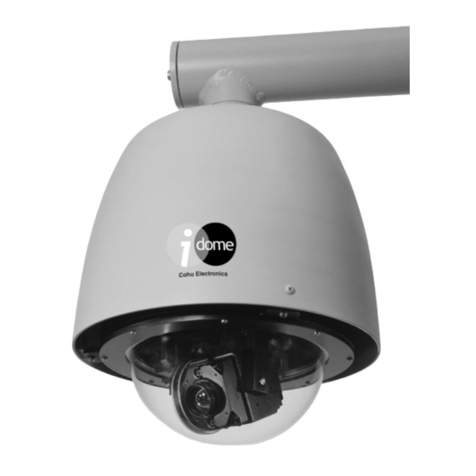
The CohuHD 3920HD (HighDenition)and3920SD (StandardDenition)Cam-
eraSystemsareIPcamerasystemsinenvironmentallysealedandpressurized
dome enclosures. The camera system provides IP video streams with H.264
and MJPEG compression plus an analog composite video output. The camera
includes variable a hi-speed pan and tilt drive with 360°continuous pan and
+5° to -90° tilt movements. The enclosures are pressurized to 3 - 5 psi and
meet International Protection rating IP67. Control interfaces are via Ethernet
network connection or RS-422 serial communications.
The 3920HD and 3920SD camera systems comply with NEMATS 2 standards for
shockandvibrationspecications.
For more information on specications and datasheets, please refer to the
CohuHD website.
1.1 Product Description
18 Pin Connector
1.5 NPT Nipple
Safety Strap
Sun Shield
Ventilation Hole
(6)
Pressure Relief Valve (5 psi)
(Protected by Plastic Tubing)
Quick Disconnect
Bottom
Schrader Valve
(Cap Installed)
Lock Down Bolts (2)
Quick Disconnect
Top
NOTE: See section 3.3 for instructions on the Quick Disconnect disassembling/reassembling.
Camera Top View
NPT - National Pipe Thread

7
6X-1097B
1.2 Equipment Supplied
The camera system is supplied with:
• An 18-pin MS type metal connector. The supplied connector is to be wired to the system intercon-
nection cable.
For more information on the connector see chapter 2.2 of this manual.
Optional Accessories
The following optional mounts and cables are recommended by CohuHD for camera system installation
and can be purchased with the Camera:
Mounts:
• Wall,CohuHDp/n7411420-001.
• Pole,CohuHDp/n7411421-001.Thepolemountisdesignedfor
use with the wall mount (see above).
For more information on each type of mount see chapter 3 of this manual.
Cables:
• CA252 series with 120V AC MS connector.
• CA255 series with 24V AC MS connector.
For more information on cables see chapter 2.3 of this manual.
2.0 Installation
This chapter covers the general installation and cable requirements of the 3920HD and3920SD series.
Before starting installation:
• Choose the installation mounting method. See chapter 3 of this manual.
• Verify that the cables can be routed to the location of the mounting assembly.
See section 3.0 for details on the installation procedure for recommended mounts.
Figures 1 and 2 show interconnection diagrams for the 3920HD/3920SD series Cameras:
• Figure 1 shows a typical set up interconnection diagram for the Camera using IP output.
• Figure 2 shows a setup of the Camera using analog and IP output.
These diagrams give an idea of a typical installation. Each installation site will have its own unique require-
ments.
Wall Mount
Pole Mount

8 6X-1097B
Network
Switch
Power
Router/Switch
CAT5e
Cable Router/Switch
WAN
LAN
System Cable
Default IPAddress
192.168.2.150
Properly secure the camera system
before the power is applied.
Cable Shield(s)
Earth
Ground
Figure 1. Interconnection Diagram, IP Output
Network
Switch
Power
Router/Switch
CAT5e
Cable
Analog
Monitor
RS-232/422 Converter
Direct plug-in
to computer
serial port
422 232
Coax Cable Serial Cable
Router/Switch
WAN
LAN
System Cable
Default IPAddress
192.168.2.150
Properly secure the camera system
before the power is applied.
Cable Shield(s)
Earth
Ground
Figure 2. Interconnection Diagram, Analog and IP Output

9
6X-1097B
2.1 System Cable Requirements
To build the Camera system cable CohuHD recommends:
• ForEthernet:CAT5eorbettercableisrecommended.Fordistancesuptoamaximumof100me-
ters(328feet),useCAT5ecablewithfourpairsofcopperwire,24AWG.
• ForAnalogVideo:Thecoaxforanalogvideoshouldberatedat75ohms,andshouldnotexceeda
maximumattenuationof6dBat10MHzforthelengthofcoaxrequired.Forexample,Belden9221
miniaturecoaxisasmall,extremelyexible,75ohmcoaxthathasanattenuationof2.2dBper100
feet.Itshouldneverbeusedfordistanceslongerthan270feet((6dB/2.2dB)x100ft.=272feet).
AnexcellentmidrangecoaxwouldbetheBelden8241F(RG-59/Utypewith100%coppercore),
withanattenuationof0.9dBper100feet,oramaximumrecommendeddistanceof650feet.For
longercableruns,theBelden8238(RG-11/Utype)hasanattenuationof0.7dBper100feet,which
wouldallowforamaximumcablelengthofover850feet.Therearetriaxialcablesavailablethat
canaccommodateevenlongercabledistances,butavideocableequalizerorberopticsmay
prove to be more cost effective as a long distance solution.
• ForData:Shielded,twotwistedpairdatacableisrecommended.Forlowerbaudrates(9,600or
less),theBelden8723shieldedcableisusuallysuitablefordistancesupto750feet.Forlonger
cableruns,and/orfasterbaudrates,acablewithalowercapacitanceperfootshouldbeselected.
TheBelden8162(12.5pf/ft.capacitance),wouldbesuitablefordistanceswellinexcessof1,000
feet at baud rates up to 115KB.
• ForPower:Threewires,insulatedfor300Vminimum,18AWGcordforpower.Usefordistances
uptomaximum750feet(230m)for115VACcables.Usefordistancesuptoamaximumof80
feet (29 m) for 24 V AC cables.
WhenwiringtotheEthernetpins,besuretoconsiderwhethertheyshouldbewiredfortheNICinaPCor
forsystemconnectionstoahub,switch,router,orsimilardevice.Seetables1,2.
Ethernet
Function Camera Connector
Ethernet Pins Corresponding
RJ-45 Ethernet Pins
Tx+ D 1
Tx- E 2
Rx+ F 3
Rx- H 6
ThisEthernetwiringisintendedtoconnectdirectlytoahub,switch,
or router. For connection directly to a PC it will be necessary to use
either a crossover cable or a crossover adapter. See table 2.
Table 1. Ethernet Cable Wiring to a Hub, Switch, or Router (Straight Wiring)
Ethernet
Function Camera Connector
Ethernet Pins Corresponding
RJ-45 Ethernet Pins
Tx+ D 3
Tx- E 6
Rx+ F 1
Rx- H 2
This Ethernet wiring is intended to connect a Camera to the NIC card
in a PC.
Table 2. Ethernet Cable Wiring to a PC (Crossover Wiring)
10 6X-1097B
In the 3920HD/3920SD series Cameras the RS-422 interface is used for sending and receiving serial data.
Therefore,aRS-232/422convertershouldbeusedbetweentheCameraandacomputer.Figure3shows
a typical RS-232/422 converter from B&B that could be used with 3920HD/3920SD. Table 3 shows cable
wiring between the Camera and a converter.
D9
FEMALE
+12V
GND
RD(B)
RD(A)
TD(A)
TD(B)
Tx+ Rx+
Tx- Rx-
232
422
B&B
converter
422PP9TB
Figure 3. Typical RS- 232/422 Converter
Table 3. RS-422 Cable Wiring to B&B Converter
Camera Side Converter Side
RS-422
Camera Camera Connector
Pins RS-422 Device
Rx+ M TD(B)
Rx- N TD(A)
Tx+ S RD(B)
Tx- R RD(A)
Alarm I/O (Future)
The 3920HD and 3920SDcamerasystemssupportthreealarmI/OchannelsidentiedasAlarm1I/O,Alarm2
I/O,andAlarm3I/OintheSystemCablediagram.Thesethreealarmchannelsaresoftwarecongurableas
inputsoroutputsandareactive-lowreferencedtotheAlarm/DataGndpin.Whenconguredasaninput,
connectingtheAlarmI/OpintotheAlarm/DataGndpinthroughanexternalswitchorrelayactivatesthe
alarminput.Whenconguredasanoutput,theAlarmI/OpinprovidesalowresistancecircuittotheAlarm/
DataGndpinwhenactivated.TheAlarmI/OoutputsupportsDCloadsonlywithamaximumvoltageof
50VDCandamaximumcurrentof0.5A.

11
6X-1097B
Figure 5. Pin Location Diagram.
MS type Mating Cable Connector
(CohuHD p/n 1310230-011)
View from the back (wiring) side
Figure 4. Pin Location Diagram.
MS type Connector
(CohuHD p/n 1310230-017)
View from the front (mating) side
2.2 18-pin MS Connector and Its Mating System Cable Connector
All system electrical connections for the 3920HD/3920SD seriesroute through an MS-type metal connector
installed in the dome housing. The connector can be wired for 115 V AC or 24 V AC operation.
A mating connector is supplied for making system interconnections.
Figure 4 is the pin location diagram of the dome connector viewed from the mating side. The view is identi-
caltothewiringviewofamatingconnector(supplied)forthesystemcable.Seegure5forthematingcon-
nector. Figure 6 and 7 show pin functions of the connector for 115 V AC and the 24 V AC. Those functions
are identical to the corresponding pin functions of the mating system cable connectors.
PIN SIGNAL
115V AC
D EthernetTx+
E EthernetTx-
F EthernetRx+
H EthernetRx-
L CompositeVideoOut
A Video Return
P Alarm/Data Gnd
C Alarm1 In/Out
J Alarm2 In/Out
K Alarm3 In/Out
M RS-422Rx+
N RS-422Rx-
S RS-422Tx+
R RS-422Tx-
G AC GND
B SPARE
U 115 VAC HI
T 115VACLO
Figure 6. MS (Metal) Connector Pinouts
for 115V AC
PIN SIGNAL
24V AC
D EthernetTx+
E EthernetTx-
F EthernetRx+
H EthernetRx-
L CompositeVideoOut
A Video Return
P Alarm/Data Gnd
C Alarm1 In/Out
J Alarm2 In/Out
K Alarm3 In/Out
M RS-422Rx+
N RS-422Rx-
S RS-422Tx+
R RS-422Tx-
G AC GND
B 24 VAC HI
U SPARE
T 24VACLO
Figure 7. MS (Metal) Connector Pinouts
for 24 V AC

12 6X-1097B
2.3 CohuHD Manufactured System Cables
CohuHDmanufactured cables are available for 3920HD/3920SD series Cameras operating from 115 V AC
power or 24 V AC with MS connectors. See table 4. Cables are made with either stripped (prepared) leads
or with various combinations of connectors and a RS-232/422 converter. “Stripped” in the tables indicates
that the wire leads are stripped and pre-tinned with solder for attachment to a terminal strip or similar device.
MaximumcablelengthforCameraswithoperatingpower24VACis80feet(29meters).Thelengthlimita-
tionisduetovoltagedropinthewires.MaximumcablelengthforCameraswithoperatingpower115VAC
is 328 feet (100 meters). This length limitation is due to Ethernet signal degradation which increases with
thecablelength.ForEthernetcableslongerthan100m(328’)anEthernetextendermayberequired.
NOTE:ThemaximumrecommendedcablelengthforEthernetis100m(328’).However,otherfactorsmay
reducethedistanceEthernetcanbesuccessfullyused,suchasEMIfromothersources.
Figures 8 and 9 show two versions of the MS system cables: CA252S for 115 V AC operating power and
CA255S for 24 V AC power.
/
1/
2/
3
/DATA
Figure 8. CohuHD Manufactured System Cable CA252S: MS, 115 V AC
Note:NC=NoConnection
Ethernet
Video
Alarm
I/O
RS422
Data
Overall
Shield
115 V AC
MS Connector
AC Plug
RJ45
BNC
Control Side
Camera Side

13
6X-1097B
/
1/
2/
3
/DATA
Figure 9. CohuHD Manufactured System Cable CA255S: MS, 24 V AC
Ethernet
Video
Alarm
I/O
RS422
Data
Overall
Shield
24 V AC
MS Connector
RJ45
BNC
Note:NC=NoConnection
Control Side
Camera Side

14 6X-1097B
Cable Volt AC Camera Side
Connector
IP Video
(Ethernet)
Connection
Power
Connection Analog Video
Connection
Serial Data Con-
nection
(RS422) Alarm Max Distance
feet (meters)
CA252A 115
18-pin MS Style
CohuHD p/n
1310230-011
stripped leads stripped leads - – – 328’ (100 m)
CA252B 115 RJ45 115 V AC Plug - – – 328’ (100 m)
CA252P 115 stripped leads stripped leads stripped leads stripped leads – 328’ (100 m)
CA252Q 115 RJ45 115 V AC Plug BNC stripped leads – 328’ (100 m)
CA252R 115 stripped leads stripped leads stripped leads stripped leads stripped leads 328’ (100 m)
CA252S 115 RJ45 115 V AC Plug BNC stripped leads stripped leads 328’ (100 m)
CA252H 115 RJ45 16-pinAMPStyleConnector,CohuHDp/n1310306-010 328’ (100 m)
115V AC Analog Video
Signal Serial Data
Signal -
CA252M 115 RJ45 115 V AC Plug BNC RJ45 stripped leads 328’ (100 m)
CA252T 115 RJ45 115 V AC Plug BNC converter
RS422 to RS232 stripped leads 328’ (100 m)
CA255A 24 stripped leads stripped leads - – – 80’ (29 m)
CA255B 24 RJ45 stripped leads - – – 80’ (29 m)
CA255R 24 stripped leads stripped leads stripped leads stripped leads stripped leads 80’ (29 m)
CA255S 24 RJ45 stripped leads BNC stripped leads stripped leads 80’ (29 m)
CA255M 24 RJ45 stripped leads BNC RJ45 stripped leads 80’ (29 m)
CA255T 24 RJ45 stripped leads BNC converter
RS422 to RS232 stripped leads 80’ (29 m)
Note: “Stripped” in the table indicates that the wire leads are stripped and pre-tinned with solder for attachment to a terminal strip or similar device.
Table 4. CohuHD Manufactured Cables CA252 and CA255 with MS Connectors

15
6X-1097B
3.0 Mounting Methods
The dome camera system is designed for indoor/outdoor installation. The following mounts are recom-
mended by CohuHD for 3920HD/3920SD series installation and can be purchased with the camera.
3.1 Wall Mount
Wall Mount Installation Diagram
Wall Mount Dimension Drawing
18.00 (45.72)
6.50
(16.51)
4.50
(11.43)
6.00
(15.24)
8.00
(20.32)
.75
(1.90) 0.31 (.95)
THRU (4X)
.75
(1.90)
2.50
(6.35)
1.75
(4.45)
Quick Disconnect
top screws directly
into mount
Secure with four 5/16” fasteners
(not supplied) suitable for the
mounting surface
1.5-inch NPT pipe
Set Screw
End Cap
Note: All dimensions in inches (cm)

16 6X-1097B
3.2 Pole Mount
The pole mount adapter is designed for use with the wall mount (see section 3.1 for a wall mount) .
12.77
(32.44)
4.50
(11.43)
6.50
(16.5)
Ø3.00 (7.62)
THRU, 2X
2.46
(6.24)
7.00
(17.78)
2.75
(6.98)
Pole Mount Adapter Dimension Drawing
Note: All dimensions in inches (cm)
Pole Mount Installation Diagram
Quick Disconnect
top screws directly
into mount
1.5-inch NPT pipe
Three stainless steel
straps are supplied.
Straps fit 3-inch (7.62 cm)
to 8-inch (20.32 cm)
diameter pole
Four 5/16-inch mounting
studs (nuts and split lock
washers supplied) for
attaching the wall mount
Set Screw
End Cap

17
6X-1097B
3.3 Installation Procedures
For installation:
• Use stainless steel hardware to fasten the Camera and mounting brackets. This will ensure the
resistance of fasteners to corrosion.
• Use anti-seize compound in order to prevent galling on the threads.
• Use gasket materials if needed.
• Use a sealant wrap on the Camera waterproof connectors and its mating system cable plugs for
additional protection against moisture in severe conditions.
Provisions must be made for routing the system cable up to the Camera location:
• PoleMounting:ifthecableroutesupthroughthepole,supportthecableinsidethepolesothatthe
full cable weight load is not solely at the Camera connector.
The sequence of installation can vary from site to site:
• Verify that the system cable can be routed to the location of the mounting assembly.
• If installing the Camera to:
• Thewallsurface,usethemountasatemplate.Markanddrillholesinthemountingsur-
face. Drill a hole for the cable if required.
• Thepole,positionthepolemountonthepoleandsecurewiththestainlesssteelmount-
ingstraps(supplied).Useaatbladescrewdriveror5/16socket(notsupplied)totighten
strap screws.
• Remove the end cap on the wall mount and route the system cable down into the arm. Reinstall
the end cap.
• If installing the Camera to:
• Thewallsurface,positionthewallmountoverthemountingholes.Securewithfour5/16-
inch fasteners (not supplied).
• Thepole,attachthewallmounttothestudsonthepolemountandsecurewiththe5/16-
inch nuts and washers (supplied).
NOTE:Ifyouinstalloutdoors,sealthefastenerholeswithanappropriatesealanttoprevent
water damage. Apply the sealant between the mount and the mounting surface.
• Install the dome (Instructions on the Quick Disconnect disassembling/reassembling).
Seegure10:
• Remove the safety strap from the top half of the Quick Disconnect (the half with the
threadednippleattached).Use3/32”hexkey.
• LoosentwolockboltsontheQuickDisconnectwitha5/16”socketapproximately1/4inch.
Do not remove lock bolts. Separate the two parts of the Quick Disconnect by rotating ap-
proximately1/16”turnCCW.
• Apply anti-seize compound on Quick Disconnect nipple threads.
WARNING:
It is the user’s responsibility to ensure that the mounting methods are safe and adequate for the location.

18 6X-1097B
• Thread the Quick Disconnect nipple into the mounting arm and tighten with a strap wrench
(not supplied).
• Tighten the set screw on the mounting arm securely.
• Route the system cable down through the nipple and attach the system cable plug to the
dome connector.
• Orient the dome properly and attach it to the other half of the Quick Disconnect mounted
tothearmbyengagingthepinsandrotatingapproximately1/16”turnCW.Ensurethat
safety strap bolts are aligned after rotation. See picture below.
• Snug lock bolts to lock the top and bottom of the Quick Disconnect together. Do not over-
tighten.
• Reattach the safety strap.
NOTE: The top part of the Quick Disconnect is intended to remain in place after installation. If
youneedtoremovetheCamera,reversetheaboveprocess.
Figure 10. Quick Disconnect Assembly
18 Pin Connector Safety
Strap
Lock Bolt
(2)
1.5 NPT Nipple
Safety strap bolts
must be aligned
1.5-inch NPT pipe
Set Screw
Quick Disconnect Top
Quick Disconnect Bottom
Safety Strap

19
6X-1097B
3920HD/3920SD Series Dome Dimensions
Note: All dimensions in inches (mm).
NPT - National Pipe Thread.
8.34
(211.83)
10.42
(264.66)
ø11.05
(280.67)
ø7.00
(177.8)
ø3.00 (76.20)
3.32 (84.32)
ø1.77 (44.95)
1.5 NPT

20 6X-1097B
4.0 Quick Check
4.1 IP Control and Viewing of Camera
Installation and testing of the Camera can be performed with the built-in Helios Web Interface application.
TheHeliosWebInterfacewasdesignedtoworkwithInternetExplorer(IE)8.MicrosoftActiveX®isrequired
to view and control video in the web interface.
• AllowtheCameratoinstallSignedActiveX®controlbeforeconnectingtotheCamera.
FormoreinformationonActiveX®controlinstallationseetheoperationmanual6x-1090,Appendix1.The
manual is shipped with the Camera.
For information on computer requirements see section 1.3 of the manual listed above.
4.2 Factory Default IP Address and Settings. Assigning the new Camera IP Address
The camera is shipped with:
• IPAddress - 192.168.2.150
• Subnet mask - 255.255.0.0
• Gateway - 192.168.2.1
No two devices on a single Ethernet network can have the same IP address. Use the following steps to
change a Camera IP address before a second camera is added to the subnet.
• Set your computer IP address to the same subnet as the Camera IP address. See the operation
manual6x-1090,section1.6.
• Change the Camera address. The Camera address can be changed manually or through a Dynam-
icHostCongurationProtocol(DHCP)server.Seetheoperationmanual6x-1090,section2.2.1.1.
• Click the Camera Setup button.
• ClicktheCongurationbutton.
• Click the Communication tab.
The Communications tab is used for performing network conguration of the Camera. Changes to this
tab can only be made by the “Admin” account. Care should be taken when modifying parameters on this
page as the changes might make the Camera inaccessible through the network. Consult with your network
administratorbeforestartingtoassignnewnetworksettingstoensurethatyourcamerawon’tconictwith
other devices.
• WritedownthenewCameraaddresstomakethecameraeasytondlater.IfthecameraIPad-
dressbecomeslost,usetheCohuONVIFDiscoverysoftwaretondthecameraonanetwork.The
software is available as a free download at http://www.CohuHD.com/content/downloads. Under
Software & Protocol Downloads see Setup & Test Applications. At Helios ONVIF Discovery Tool
click “download here.”
This manual suits for next models
1
Table of contents
Other COHU Security Camera manuals

COHU
COHU Series 7520HD User manual

COHU
COHU 7420HD series User manual

COHU
COHU 3220 Series User manual

COHU
COHU iDOME 3920 Series User manual

COHU
COHU 2900 Series User manual

COHU
COHU 3940 Analog iDome User manual

COHU
COHU 3610 Series Product manual

COHU
COHU 7510HD SERIES User manual

COHU
COHU 2740 SERIES User manual

COHU
COHU Helios 3960 User manual