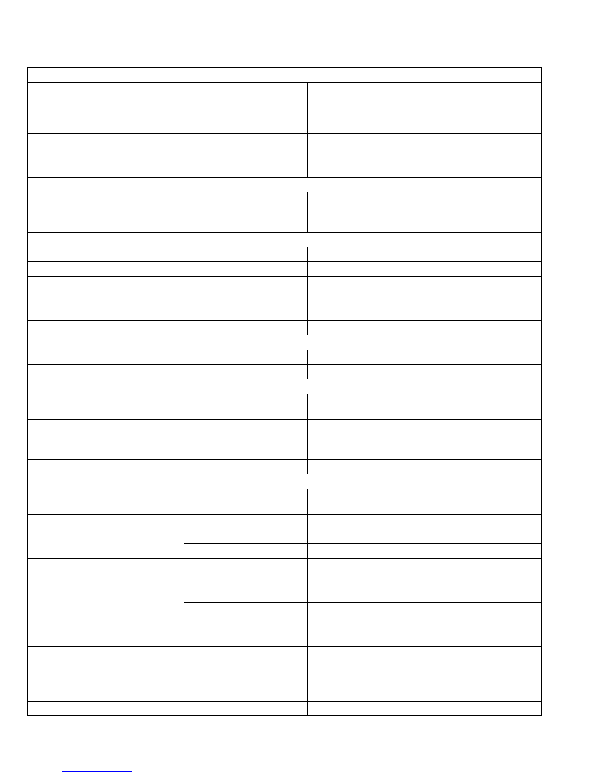
JVC HX-Z30 User manual

SERVICE MANUAL
COPYRIGHT © 2003 VICTOR COMPANY OF JAPAN, LIMITED No.MB043
2003/10
COMPACT COMPONENT SYSTEM
MB04320039HX-Z30
TABLE OF CONTENTS
1 PRECAUTION. . . . . . . . . . . . . . . . . . . . . . . . . . . . . . . . . . . . . . . . . . . . . . . . . . . . . . . . . . . . . . . . . . . . . . . . . 1-3
2 SPECIFIC SERVICE INSTRUCTIONS. . . . . . . . . . . . . . . . . . . . . . . . . . . . . . . . . . . . . . . . . . . . . . . . . . . . . . 1-5
3 DISASSEMBLY . . . . . . . . . . . . . . . . . . . . . . . . . . . . . . . . . . . . . . . . . . . . . . . . . . . . . . . . . . . . . . . . . . . . . . . 1-6
4 ADJUSTMENT . . . . . . . . . . . . . . . . . . . . . . . . . . . . . . . . . . . . . . . . . . . . . . . . . . . . . . . . . . . . . . . . . . . . . . . 1-36
5 TROUBLESHOOTING . . . . . . . . . . . . . . . . . . . . . . . . . . . . . . . . . . . . . . . . . . . . . . . . . . . . . . . . . . . . . . . . . 1-41
Area Suffix
UW ------ Brazil,Peru,Mexico

1-2 (No.MB043)
SPECIFICATION
Design & specifications are subject to change without notice.
Amplifier section-CA-HXZ30
Output Power (IEC 268-3) SUBWOOFERS 135 W per channel, min. RMS, driven into 6 Ωat 63 Hz with
no more than 10% total harmonic distortion.
MAIN SPEAKERS 55 W per channel, min. RMS, driven into 6 Ωat 1 kHz with
no more than 10% total harmonic distortion.
Audio input sensitivity/impedance
(Measured at 1 kHz, with tape recording
signal 300 mV)
AUX 300 mV/47 kΩ
Speakers/
impedance SUBWOOFERS 6 Ω- 16 Ω
MAIN SPEAKERS 6 Ω- 16 Ω
Tuner
FM tuning range 87.50 MHz - 108.00 MHz
AM tuning range At 9 kHz intervals 531 kHz - 1 710 kHz
At 10 kHz intervals 530 kHz - 1 710 kHz
CD player
Disc capacity 5 discs
Dynamic range 87 dB
Signal-to-noise ratio 90 dB
Wow and flutter Immeasurable
MP3 recording format MPEG 1/2 Audio Layer 3
Max. Bit rate 320 kbps
Cassette deck
Frequency response Normal (type I) 50 Hz - 14 000 Hz
Wow and flutter 0.15% (WRMS)
General
Power requirement AC 110 V/AC 127 V/AC 220 V/AC 230 V - AC 240 V
(adjustable with the voltage selector), 50 Hz / 60 Hz
Power consumption 210 W (in operation)
28 W (on standby)
Dimensions (approx.) 205 mm ×370 mm ×380.5 mm (W/H/D)
Mass (approx.) 10.5 kg
Speaker section-SP-HXZ30
Type 3-way 4-speaker Bass-Reflex Type Twin Hyper Power-Drive
Subwoofers and Front Twin Woofer
Speakers Subwoofer 20.0 cm (7-7/8 in.) cone ×1
Main woofer 13.5 cm (5-3/8 in.) cone ×2
Tweeter 5.0 cm (2 in.) cone ×1
Power Handling Capacity Subwoofer 190 W
Main Speaker 80 W
Impedance Subwoofer 6 Ω
Main Speaker 6 Ω
Frequency Range Subwoofer 30 Hz - 818 Hz
Main Speaker 75 Hz - 30 000 Hz
Sound Pressure Level Subwoofer 81 dB/W·m
Main Speaker 88 dB/W·m
Dimensions (W ×H ×D) 247 mm ×452 mm ×391 mm
(9-3/4 in.×17-13/16 in. ×15-7/16 in.)
Mass 10 kg (22.1 lbs) each

1-6 (No.MB043)
SECTION 3
DISASSEMBLY
3.1 Main body
3.1.1 Removing the metal cover
(See Fig.1~3)
(1) Remove the six screws Aon the back of the body.
(2) Remove the screw Bon each side of the body.
(3) Remove the metal cover from the body by lifting the rear
part of the cover.
CAUTION:
Do not break the front panel tab fitted to the metal cover.
Fig.1
Fig.2
Fig.3
A
AA
Metal cover
Metal cover
B
Metal cover
B

(No.MB043)1-7
3.1.2 Removing the CD changer mechanism assembly
(See Fig.4, 5)
• Prior to performing the following procedure, remove the metal
cover.
(1) Disconnect the card wire from connector CN651 on the CD
servo control board on the right bottom of the CD changer
mechanism assembly.
(2) Remove the four screws Cattaching the CD changer
mechanism assembly on top of the body.
(3) Remove the CD changer mechanism assembly while lifting
the rear part.
CAUTION:
Do not damage the CD fitting when removing the CD changer
mechanism assembly.
Fig.4
Fig.5
CD changer mechanism assembly
CD servo control board
CN651
Front panel assemby
CD changer
mechanism assembly
CC

1-8 (No.MB043)
3.1.3 Removing the front panel assembly
(See Fig.6~9)
• Prior to performing the following procedure, remove the metal
cover and the CD changer mechanism assembly.
(1) Disconnect the card wires from connector CN44 and
CN870 on the main board on the right side of the body.
(2) Disconnect the wire from connector CN701 on the bridge
board.
(3) Cut the band.
(4) Disconnect the wire from connector CN231 on the primary
board on the left side of the body and remove the band
fixing the wire.
(5) Disconnect the ground wire extending from phones board
from bottom chassis.
(6) Remove the three screws Dattaching the front panel
assembly at the bottom of the body.
(7) Release the two joints aon the lower left and right sides of
the front panel assembly using a screwdriver, and remove
the front panel assembly toward the front.
REFERENCE:
Front panel need to be tilt a little bit as release from bottom
chassis.
Fig.6
Fig.7
Fig.8
Fig.9
Front panel assembly
Bridge board
CN701
Main board
CN870
CN44
a
Front panel assembly
Primary board
CN231
Band
a
Ground wire
Band
Primary board
CN231 Front panel assembly
Front panel aeembly
D

(No.MB043)1-9
3.1.4 Removing the tuner pack assembly
(See Fig.10, 11)
• Prior to performing the following procedure, remove the metal
cover and the CD changer mechanism assembly.
(1) Disconnect the card wire from connector CN1 on the tuner
pack assembly on the right side of the body.
(2) Remove the two screws Eon the rear panel on the back of
the body.
Fig.10
Fig.11
Tuner pack assembly
CN1
ERear panel

1-10 (No.MB043)
3.1.5 Removing the rear panel
(See Fig.10, 12~16)
• Prior to performing the following procedure, remove the metal
cover and the CD changer mechanism assembly.
(1) Remove holding board by remove a plastic rivet and then
slide out the holding board as shown in fig. 12.
(2) Disconnect the fan wire extending from the fan assembly
from connector CN206 on the bridge board.
(3) Disconnect the card wire from connector CN1 on the tuner
pack.
(4) Remove four screws Ffrom rear panel.
(5) Release joints bwhich on right bottom and left bottom of
rear panel. The joint can be release by pull outward the
side of rear panel.
REFERENCE:
Fan assembly and tuner pack will come off with rear panel.
Fig.12
Fig.13
Fig.14
Fig.15
Fig.16
Plastic rivet
Holding board
Rear panel
Fan assembly Bridge board
CN206
FF
F
Rear panel
Rear panel
b
Rear panel
b

(No.MB043)1-11
3.1.6 Rmoving the fan assembly
(See Fig.17, 18)
• Prior to performing the following procedure, remove the metal
cover, the CD changer mechanism assembly and the rear
panel.
(1) Cut the band holding the fan wire.
(2) Remove two screws Gon the rear panel.
(3) Rotate fan assembly in clockwise direction to release fan
assembly from rear panel (joints c).
Fig.17
Fig.18
3.1.7 Removing the main board
(See Fig.19)
• Prior to performing the following procedure, remove the metal
cover, the CD changer mechanism assembly and the rear
panel.
(1) Cut off the band.
(2) Disconnect the card wires from connector CN44 and
CN870 on the main board.
(3) Remove the screw H attaching the main board.
(4) Disconnect connector CN217 and CN311 on the main
board outward and release from the base chassis (joint d)
upward.
Fig.19
G
Rear panel
c
cFan assembly
Band
CN870
CN44
CN311
Main board
CN217
Band
Hd

1-12 (No.MB043)
3.1.8 .Removing the bridge board / regulator board / heat sink
(See Fig.20~23)
• Prior to performing the following procedure, remove the metal
cover, the CD changer mechanism assembly, the rear panel
and main board.
(1) Disconnect the wire from connector CN212, CN213 and
CN214 on the primary board respectively and remove the
band attaching the wires.
(2) Disconnect the wire from connector CN701 on the bridge
board.
(3) Disconnect the ground wire extending from the bridge
board from bottom chassis.
(4) Remove the two screws Iattaching the heat sink bracket
and move the heat sink in the direction of the arrow to
release from the base chassis. The bridge board and the
regulator board come off with the heat sink.
(5) Remove the two screws Jattaching the heat sink bracket.
(6) Remove the two screws M, detach bridge board from
regulator board by disconnect connector CN205.
(7) Remove the two screws Kand two screws Lto detach
regulator board from heat sink.
CAUTION:
As assembly back the regulator board and bridge board to
heat sink.
Regulator board must be assembly to heat sink first and
screws Kand L must be screwed before bridge board attach
to regulator board.
Fig.20
Fig.21
Fig.22
Fig.23
Band
CN212
Primary board
CN213
CN214
CN701
Bridge board
Bridge board
Ground wire
Regulator board
Heat sink
I
IHeat sink bracket
J
Heat sink
Bridge board
Regulator board
Heat sink bracket
Heat sink bracket
Heat sink
Regulator board
Bridge board
CN215
CN205
L
K
ML

(No.MB043)1-13
3.1.9 Removing the power transformer assembly
(See Fig 24, 25)
• Prior to performing the following procedure, remove the metal
cover, the CD changer mechanism assembly, the rear panel,
the main board and the bridge board / regulator board.
(1) Remove the screw N attaching the primary board.
(2) Disconnect the wire from connector CN231 on the primary
board.
(3) Remove the four screws Oattaching the power
transformer assembly.
(4) Detach the cord stopper from the base chassis upward.
REFERENCE:
When disconnecting the power cord from connector CN250 on
the primary board, remove the fixing band.
Fig.24
Fig.25
Power transformer
assembly
Primary board
N
Primary board
CN231
CN250
Cord stopper
FIxing band
Power transformer
assembly
OO

1-14 (No.MB043)
3.2 Front panel assembly
• Prior to performing the following procedure, remove the metal
cover, the CD changer mechanism assembly and the front
panel assembly.
3.2.1 Removing the cassette mechanism assembly
(See Fig.26)
(1) Disconnect the card wire from connector CN33 on the head
amplifier & mechanism control board.
(2) Remove the two screws P, and the two screws Q
attaching the cassette mechanism assembly.
3.2.2 Removing the headphone board (See Fig.26)
(1) Remove the screw R and pull out the headphone board
backward.
(2) Cut off the band.
Fig.26
3.2.3 Rmoving the switch / micon board
(See Fig.27~29)
• Prior to performing the following procedure, disconnect the
card wire from CN43 on the micon board.
(1) Disconnect the card wire from connector CN840 on the
micon board.
(2) Remove the fifteen screws Sattaching the switch / micon
board.
(3) Remove the spacer fixing the wire.
(4) Move the switch /micon board in the direction of the arrow
to disconnect the wire from connector CN880 and CN900
on the micon board.
Fig.27
Fig.28
Fig.29
Head amplifier &
mechanism control board
CN33
Headphone board
PQ
QR
Band
S
S
S
S
CN43
Micon board
CN840
Switch board
Spacer
Spacer
Switch board
CN880
Switch board
CN900
Micon board
CN43
CN840

(No.MB043)1-15
3.2.4 Removing the FL board assembly
(See Fig.30, 31)
• Prior to performing the following procedure, remove the switch
/ micon board.
(1) Remove the five screws Tattaching the stay bracket (1).
(2) Remove the three screws Uattaching the FL board
assembly.
Fig.30
Fig.31
T
Stay bracket (1)
U
UU
FL board assembly

1-16 (No.MB043)
3.2.5 Removing the button board
(See Fig.32~35)
• Prior to performing the following procedure, remove the switch
/micon board.
(1) Pull out the preset knob, the volume knob and the sound
mode knob.
(2) Remove the two screws Vattaching the knob holder.
Remove the nut from the front panel.
(3) Remove the eleven screws Wattaching the button board.
Fig.32
Fig.33
Fig.34
Fig.35
Preset knob
Volume knob
Sound mode knob
V
Knob holder
Nut
W
W
W
Volume baord

(No.MB043)1-17
3.3 CD changer mechanism
3.3.1 Removing the tray assembly
(See Fig.1 ~ 5)
(1) Remove the two screws Afrom the top cover and release
the two joints aon both sides of the body.
(2) Remove the top cover with the two rods attached to the top
cover and lifter assembly respectively.
(3) Remove the open det lever on the left side of the body.
(4) Push part b of the slide (R) assembly on the right side of
the body to unlock the tray assembly. Draw out the trays
toward the front.
Attention:
The tray can be locked if all tray assemblies are
attached.
(5) From top of the body, move the stopper tab c in the
direction of the arrow and release. Pull out the tray
assemblies from the body.
Caution:
Remove the tray assembly from top tray 5 in order.
Attention:
When reattaching the sub tray of the tray assembly, or when
removing the CD remaining inside, refer to another section.
Fig.1
Fig.2
Fig.3
Fig.4
Fig.5
Top cover
Lifter assembly
Rod
A
a
a
A
aRod Top cover
Lifter assembly
a
Open det leve
r
b
Tray assembly
(Tray 5)
c

1-18 (No.MB043)
3.3.2 Removing the servo control board
(See Fig.6 ~ 9)
Caution:
Solder the short-circuit point on the pickup before
disconnecting the card wire extending from the pickup. If you
do not follow this instruction, the pickup may be damaged.
(1) Disconnect the card wire from connector CN251 and each
wire from connector CN252, CN253 and CN602 on the
servo control board on the bottom of the body. Disconnect
the wire from joint d.
(2) Solder the short round point on the flexible board of the pick
up.
(3) Remove the four screws Band turn the servo control board
as shown in the figure.
(4) Disconnect the card wire from connector CN601 on the
servo control board.Caution: Unsolder the short-circuit
point after reassembling.
Caution:
When reassembling, twist the wires to be connected to
connector CN252 and CN253 twice.
3.3.3 Removing the switch board
(See Fig.9)
(1) Disconnect the wires from connector CN252 and CN253
on the servo control board.
(2) Remove the screw Cattaching the switch board.
(3) Release the wires from the slot e of the switch board.
Caution:
When reassembling, let the wires through the slot eof the
switch board and twist them twice.
Fig.6
Fig.7
Fig.8
Fig.9
3.3.4 Removing the motor board (See Fig.10 , 11)
B
B
B
d
CN602
CN251
Switch board
Servo control board
CN252
CN253
Pickup
Flexible board
Short round
Card wire
CN601
Servo control board
Card wire
CN252
e
C
Servo control board
CN253
Switch board

(No.MB043)1-19
• Prior to performing the following procedure, remove the servo
control board.
(1) Turn over the body and remove the two screws D. Move
the CD module bkt. in the direction of the arrow to release
two joints f.
(2) Unsolder the four soldered parts on the motor of the motor
board.
Caution:
If removing the motor board with the motor, you should
remove the screws attaching the motor from top of the
body(Refer to another section).
(3) Remove the two screws Eattaching the motor board.
(4) Remove the spacer fixing the motor board and tray switch
board, and disconnect connector CN2 on the motor board.
(5) Disconnect the card wire from connector CN1 on the motor
board.
Caution:
When reconnecting the card wire, let the card wire through the
slot g of the motor board and attach it to the bottom of the body
using a double tape.
Fig.10
Fig.11
DD
f
CD Module
braket
f
E
g
CN2
Spacer
Card wire
Double
face tape
Motor
Soldering point
CN1
E

1-20 (No.MB043)
3.3.5 Removing the CD tramecha assembly
(See Fig.12)
• Prior to performing the following procedure, remove the servo
control board.
(1) Turn over the body and remove the three screws F
attaching the tramecha.
Fig.12
F
CD Tramecha assembly
F
F

(No.MB043)1-21
3.3.6 Removing the pickup
(See Fig.13 , 14)
• Prior to performing the following procedure, remove the servo
control board and CD tramecha assembly.
(1) From top of the CD tramecha assembly, turn the cam gear
in the direction of the arrow to move the pickup assembly
outward.
(2) Push down the stopper hin the direction of the arrow and
pull out the shaft.
(3) Release the joint iof the pickup assembly and mecha
base.
(4) Remove the screw Gattaching the CD rack. Release the
four tabs jat the bottom of the CD rack.
Fig.13
Fig.14
h
iPickup assembly
Mecha base
Shaft
ShaftShaft
Cam gear
Stopper
Stopper
CD lack
Pickup
G
j
j
j

1-22 (No.MB043)
3.3.7 Removing the side (L)/ tray switch board
(See Fig.15 ~ 17)
• Prior to performing the following procedure, remove the tray
assembly.
(1) Remove the two screws Hattaching the side (L) on top of
the body.
(2) From the side of the body, remove the spacer fixing the tray
switch board and motor board. Disconnect connector CN3
on the tray switch board and detach the side (L) upward.
(3) Remove the screw Jattaching the tray switch board.
(4) Push the joint tab kof the side (L) in the direction of the
arrow and remove the tray switch board outward, then
release joint l.
Fig.15
Fig.16
Fig.17
H
H
Side (L)
CN3
Spacer
Side (L)
H
H
k
l
J
Side (L)
Tray switch board

(No.MB043)1-23
3.3.8 Removing the side (R) assembly
(See Fig.18 ~ 22)
• Prior to performing the following procedure, remove the tray
assembly.
(1) Push and release the two tabs mof the gear cover through
the two notches inside the side (R) assembly. Remove the
gear cover outward.
(2) Remove the spring attached to part nof the hook on the
right side of the body.
(3) From top of the body, turn the 1 gear clockwise to move the
elevator cam rearward.Move the two slots oand joint pof
the elevator cam as shown in Fig.21 and remove the
elevator cam outward.
(4) Remove the three screws Kand detach the side (R)
upward.
Caution:
When reattaching the side (R) assembly, make sure to fit the
shaft (part q) into the slot of the select lever.
Fig.18
Fig.19
Fig.20
Fig.21
Fig.22
K
Side (R)
assembly
K
Kq
Side (R) assembly
Sprihg
Gear cover
Elevator com
n
1 gear
m
Side (R) assembly
Elevator cam
Spring
n
oo
p
Side (R) assembly
K
K
Other manuals for HX-Z30
4
Table of contents
Other JVC Speakers System manuals