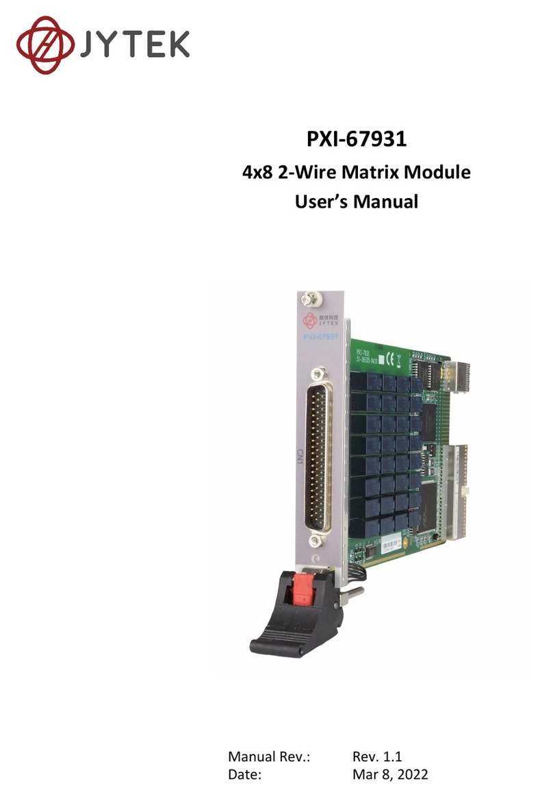
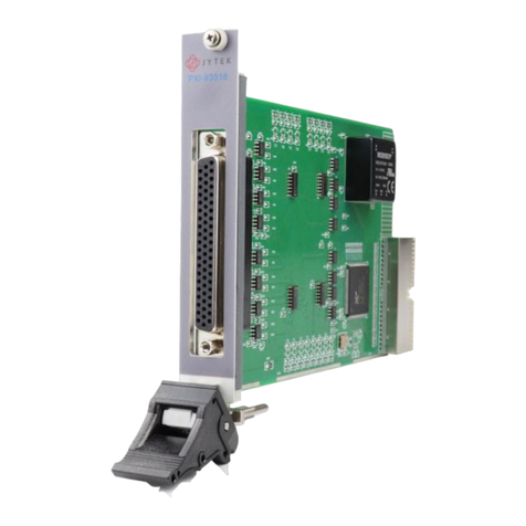
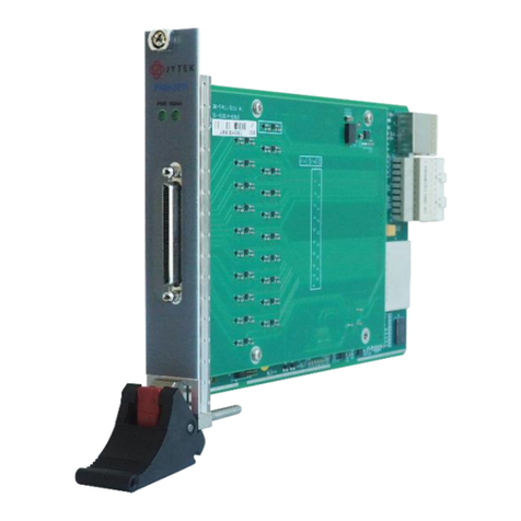
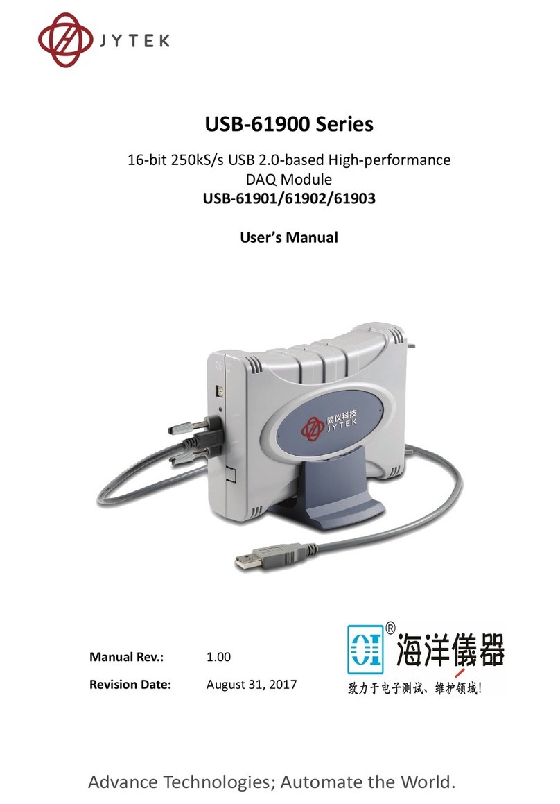
JYTEK PXIe-69529 User manual

PXIe-69529
8-CH 24-Bit 204.8 kS/s
Dynamic Signal Acquisition Module
User’s Manual
Manual Rev.: 1.00
Revision Date: Jul.16,2016

I
Getting Service
Contact us should you require any service or assistance.
SHANGHAI JYTEK Co., Ltd.
Web site: hp://www.jytek.com
Address: 300 Fang Chun Rd., Zhangjiang Hi-Tech Park, Pudong New Area, Shanghai, 201203
China
Tel: +86-21-5047-5899
Fax: +86-21-5047-5899
Email: [email protected]
Addional informaon, aids, and ps that help users perform tasks
Informaon to prevent minor physical injury, component damage, data loss,
and/or program corrupon when trying to complete a task.
Informaon to prevent serious physical injury, component damage, data loss,and/
or program corrupon when trying to complete a specic task.

II
Table of Contents
Geng Service �������������������������������������������������������������������������������������������������� I
1 Introducon������������������������������������������������������������������������������������������������ 1
1�1 Features ��������������������������������������������������������������������������������������������� 1
1.2 Applicaons ��������������������������������������������������������������������������������������� 1
1.3 Specicaons ������������������������������������������������������������������������������������� 2
1�3�1 Analog Input ��������������������������������������������������������������������������� 2
1�3�2 Timebase �������������������������������������������������������������������������������� 4
1�3�3 Triggers ����������������������������������������������������������������������������������� 4
1.3.4 General Specicaons ������������������������������������������������������������� 4
1.4 Soware Support ������������������������������������������������������������������������������� 5
1�4�1 SDK ����������������������������������������������������������������������������������������� 5
1�4�2 DSA-DASK�������������������������������������������������������������������������������� 5
1�5 Device Layout and I/O Array��������������������������������������������������������������� 6
2 Geng Started�������������������������������������������������������������������������������������������� 8
2.1 Installaon Environment �������������������������������������������������������������������� 8
2�2 Installing the Module ������������������������������������������������������������������������� 9
3 Operaons �������������������������������������������������������������������������������������������������10
3.1 Funconal Block Diagram������������������������������������������������������������������10
3�2 Analog Input Channel������������������������������������������������������������������������10
3.2.1 Analog Input Front-End Conguraon ������������������������������������10
3�2�2 Input Range and Data Format�������������������������������������������������11
3�2�3 ADC and Analog Input Filter ���������������������������������������������������12
3�2�4 DMA Data Transfer�����������������������������������������������������������������12
3�3 Trigger Source and Trigger Modes������������������������������������������������������14
3�4 Trigger Mode�������������������������������������������������������������������������������������16
3�5 ADC Timing Control ���������������������������������������������������������������������������18
3�5�1 Timebase �������������������������������������������������������������������������������18
3�5�2 DDS Timing vs� ADC����������������������������������������������������������������18
3�5�3 Filter Delay in ADC �����������������������������������������������������������������19
3.6 Synchronizing Mulple Modules �������������������������������������������������������19
3.6.1 SSI_TIMEBASE ������������������������������������������������������������������������20
3�6�2 SSI_SYNC_START ��������������������������������������������������������������������20
3�6�3 SSI_TRIG���������������������������������������������������������������������������������20
Appendix A Calibraon �����������������������������������������������������������������������������������21
A.1 Calibraon Constant �������������������������������������������������������������������������21
A.2 Auto-Calibraon �������������������������������������������������������������������������������21
Important Safety Instrucons ��������������������������������������������������������������������������22

III

IV
List of Tables
Table 1-1: Channel Characteriscs�������������������������������������������������������������������� 2
Table 1-2: Timebase����������������������������������������������������������������������������������������� 4
Table 1-3: Trigger Source & Mode �������������������������������������������������������������������� 4
Table 1-4: Digital Trigger Input ������������������������������������������������������������������������� 4
Table 3-1: Input Range and Data Format ���������������������������������������������������������11
Table 3-2: Input Range Midscale Values ����������������������������������������������������������12
Table 3-3: ADC Sample Rates vs DDS Output Clock������������������������������������������12
Table 3-4: Preferred Characteriscs for Analog Triggers�����������������������������������16
Table 3-5: Timing Relaonship between ADC and PLL Clock ����������������������������18
Table 3-6: ADC Filter Delay������������������������������������������������������������������������������19
Table 3-7: SSI Timing Signal Denions �����������������������������������������������������������19

V
List of Figures
Figure 1-1: Analog Input Channel Bandwidth, ±0.2 Vpp ������������������������������������ 3
Figure 1-2: Analog Input Channel Bandwidth, ±2 Vpp ��������������������������������������� 3
Figure 1-3: PXIe-69529 schemac ��������������������������������������������������������������������� 6
Figure 1-4: PXIe-69529 I/O Array����������������������������������������������������������������������� 7
Figure 3-1: Analog Input Architecture ��������������������������������������������������������������10
Figure 3-2: Linked List of PCI Address DMA Descriptors������������������������������������13
Figure 3-3: Trigger Architecture������������������������������������������������������������������������14
Figure 3-4: External Digital Trigger �������������������������������������������������������������������14
Figure 3-5: Analog Trigger Condions ��������������������������������������������������������������16
Figure 3-6: Post-Trigger Acquision������������������������������������������������������������������17
Figure 3-7: Delay Trigger Mode Acquision������������������������������������������������������17
Figure 3-8: Re-Trigger Mode Acquision ����������������������������������������������������������18
Figure 3-9: Timebase Architecture �������������������������������������������������������������������18
Figure 3-10: SSI Architecture����������������������������������������������������������������������������20

1
1 Introduction
The PXIe-69529 is a high-performance 8-CH 24-Bit 204.8 kS/s dynamic signal acquision
module, specically designed for applicaons such as structural health monitoring, noise,
vibraon, and harshness (NVH) measurement, and phased array data acquision.
The PXIe-69529 features 24-bit simultaneous sampling at 204.8 kS/s over 8 channels,
and a 110 dB dynamic range, providing ample power for high-density, high channel count
signal measurement, and vibraon-opmized lower AC cuto frequency of 0.3 Hz. All input
channels incorporate 4 mA bias current for integrated electronic piezoelectric (IEPE) signal
condioning for accelerometers and microphones.
The PXIe-69529 is auto-calibrated with an onboard reference circuit calibrang oset and
acquiring analog input errors. Following auto-calibraon, the calibraon constant is stored
in EEPROM, such that these values can be loaded and used as needed by the board. There
is no requirement to calibrate the module manually.
1�1 Features
• PXI Express specicaon Rev. 1.0 compliant
• 8 simultaneous analog inputs
• 204.8 kS/s maximum sampling rate
• AC or DC input coupling, soware selectable
• Support for:
◦ One external digital trigger input
◦ IEPE output on each analog input, soware congurable
◦ Auto-calibraon
1�2 Applications
• Structural health monitoring
• Phase array data acquision
• Noise, vibraon, and harshness (NVH) detecon
• Machine status monitoring

2
1�3 Specifications
1�3�1 Analog Input
Channel Characteriscs Comment
Channels 8
Type Dierenal or Pseudo-Dierenal
Coupling AC or DC, soware selectable
AC coupling cuto frequency 0.5Hz
ADC resoluon 24-Bit
ADC type Delta-sigma
Input signal range ±10V, ±1V
Sampling rate (fs) 8 kS/s to 204.8 kS/s,
768 μS/s increments for fs > 108 kS/s,
576 μS/s increments for 54 kS/s ≤ fs
≤108 kS/s
Over voltage protecon Dierenal: ±42.4V, Pseudo-
dierenal:
• posive terminal ±42.4 V
• negave terminal unprotected,
rated at ±2.5 V
Input impedance 1MΩ, (50Ω between negave input and
system ground for pseudo-dierenal
mode)
Oset error ±1 mV max.
Gain error ±0.1% of FSR
SNR, @n = 1kHz 103 dB fs = 8.0 kS
104 dB fs = 54.0 kS
99 dB fs = 108 kS
98 dB fs = 192 kS
THD < -106 dB
SFDR > 106 dB
crosstalk < -100 dB
-3 dB bandwidth >0.4863 fs fs < 108 kS
≌ 0.2 fs fs > 108 kS
IEPE
Current 4 mA, each channel independently
soware congurable
Compliance 24V
Table 1-1: Channel Characteriscs

3
0 1 2 3 4 5 6
x 10
4
−25
−20
−15
−10
−5
0
Magnitude Response
Frequency (Hz)
Magnitude (dB)
Figure 1-1: Analog Input Channel Bandwidth, ±0.2 Vpp
0 1 2 3 4 5 6 7 8 9 10
−12
−10
−8
−6
−4
−2
0Response when AC coupling enabled
Frequency (Hz)
Magnitude (dB)
Figure 1-2: Analog Input Channel Bandwidth, ±2 Vpp

4
1�3�2 Timebase
Sampling Clock
Timebase opons Internal: onboard synthesizer
External: PXI_CLK10, PXIe_CLK100
Timebase accuracy < ± 25ppm
Table 1-2: Timebase
1�3�3 Triggers
Trigger Source & Mode
Trigger source Soware, external digital trigger, analog trigger, PXI trigger
bus[0..7], PXI_STAR, and PXIe_DSTARB
Trigger mode Post trigger and delay trigger
Table 1-3: Trigger Source & Mode
Digital Trigger Input
Sources Front panel SMA connector
Compability 3.3 V TTL, 5 V tolerant
Input high threshold 2.0 V
Input low threshold (VIL) 0.8 V
Maximum input overload -0.5 V to +5.5 V
Trigger polarity Rising or falling edge
Pulse width 20 ns minimum
Table 1-4: Digital Trigger Input
1�3�4 General Specifications
Physical
Physical dimensions 160 W x 100 H mm (6.24 x 3.9 in)
Bus
Bus interface PCI Express Gen1 x 4
Environmental Tolerance
Operang Temperature: 0°C - 55°C
Relave humidity: 10% - 90%, non-condensing
Storage Temperature: -20°C - +80°C
Relave humidity: 10% - 90%, non-condensing
Calibraon
Onboard reference +5.000 V
Temperature coecient < 5.0 ppm/°C
Warm-up me 15 minutes

5
Power Consumpon
Power Rail Standby Current (mA) Full Load (mA)
+3.3 V 102 102.2
+12 V 20 20
+5V 1920 2010
1.4 Software Support
JYTEK provides versale soware drivers and packages to suit various user approaches to
building a system. Aside from programming libraries, such as DLLs, for most Windows-based
systems, JYTEK also provides drivers for other applicaon environments.
1�4�1 SDK
For customers who want to write their own programs, JYTEK provides the following soware
development kits.
• .NET driver for Windows, compable with various applicaon environments, such as
C#, VB.NET, VC.NET, VB/VC++, BCB, and Delphi
1�4�2 DSA-DASK
DSA-DASK includes device drivers and DLL for Windows XP/7/8. DLL is binary compable
across Windows XP/7/8. This means all applicaons developed with DSA-DASK are
compable with these Windows operang systems. The development environment may be
VB, VB.NET, VC++, BCB, and Delphi, or any Windows programming language that allows
calls to a DLL. The DSA-DASK user and funcon reference manuals are on the JYTEK website
(www.jytek.com).

6
1�5 Device Layout and I/O Array
All dimensions are in mm.
Figure 1-3: PXIe-69529 schematic

7
The PXIe-69529 I/O array is labeled to indicate connecvity, as shown.
Figure 1-4: PXIe-69529 I/O Array

8
2 Getting Started
This chapter describes proper installaon environment, installaon procedures, package
contents and basic informaon users should be aware of regarding the PXIe-69529.
Diagrams and illustrated equipment are for reference only.
Actual system conguraon and specicaons may vary.
2.1 Installation Environment
When unpacking and preparing to install, please refer to Important Safety Instrucons.
Only install equipment in well-lit areas on at, sturdy surfaces with access to basic tools
such as at- and cross-head screwdrivers, preferably with magnec heads as screws and
standos are small and easily misplaced.
Recommended Installaon Tools
• Phillips (cross-head) screwdriver
• Flat-head screwdriver
• An-stac wrist strap
• Anstac mat
JYTEK PXIe-69529 DSA modules are electrostacally sensive and can be easily damaged by
stac electricity. The module must be handled on a grounded an-stac mat. The operator
must wear an an-stac wristband, grounded at the same point as the an-stac mat.
Inspect the carton and packaging for damage. Shipping and handling could cause damage to
the equipment inside. Make sure that the equipment and its associated components have
no damage before installaon.
The equipment must be protected from stac discharge and physical shock.
Never remove any of the socketed parts except at a stac-free workstaon. Use
the an-stac bag shipped with the product to handle the equipment and wear a
grounded wrist strap when servicing.
Package Contents
• PXIe-69529 dynamic signal acquision module
If any of these items are missing or damaged, contact JYTEK.
Do not install or apply power to equipment that is damaged or missing
components. Retain the shipping carton and packing materials for inspecon.
Please contact your JYTEK immediately for assistance and obtain authorizaon
before returning any product.

9
2�2 Installing the Module
1. Turn o the PXI system/chassis and disconnect the power cable from the power
source.
2. Align the module edge with the module guide in the PXI chassis.
3. Slide the module into the chassis unl resistance is felt from the PXI connector.
4. Push the ejector upwards and rmly seat the module into the chassis.
5. Once the module is fully seated, a “click” can be heard from the ejector latch.
6. Tighten the screw on the front panel.
7. Connect the power plug to a power source and turn on the PXI system/chassis.

10
3 Operations
This chapter contains informaon regarding analog input, triggering and ming for the PXIe-
69529.
3.1 Functional Block Diagram
3�2 Analog Input Channel
3.2.1 Analog Input Front-End Configuration
24-bit ADC
JFET OPAMP
JFET OPAMP
330nF / 25V
CAL+
CAL-
IEPE-
1MR
1MR
330nF / 25V
SPST
SPST
IEPE+
49.9R
SPST
CARR
DATA
ADC Ctrl
SCK
Vref
Vref 10k
10k
10k
10k
Cal+
PGA
Signal Switch
X1
X10
Figure 3-1: Analog Input Architecture
Dierenal and Pseudo-Dierenal Input Conguraon
The PXIe-69529 provides both dierenal and psuedo-dierenal input conguraons,
with dierenal input mode providing voltage to the anode and cathode inputs of the
SMB connector according to signal voltage dierence therebetween. If the signal source is
ground-referenced, dierenal input mode can be used for common-mode noise rejecon.

11
If the signal source is a oang signal, pseudo-dierenal input mode can provide a
reference ground connected to the cathode input of the SMB through a 50 Ω resistor,
prevenng the oang source from driing over the input common-mode range.
Recommended conguraons for the signal sources are as follows.
Signal Source Type Card Conguraon
Floang Pseudo Dierenal
Ground-Reference Dierenal
AC and DC Input Coupling
AC and DC coupling are available. With DC coupling, DC oset present in the input signal
is passed to ADC, and is indicated if the signal source has a small level of oset voltage or
if DC content of the signal is important. In AC coupling, the DC oset present in the input
signal is erased, and is indicated if the DC content of the input signals is to be rejected. AC
coupling enables a high pass R-C lter through the input signal path. The corner frequency
(-3dB) is about 0.5Hz.
Input for IEPE
For applicaons that require sensors such as accelerometers or microphones, the PXIe-
69529 provides an excitaon current source. The common excitaon current is usually
about 4mA for these IEPE sensors. A DC voltage oset is generated due to the excitaon
current and sensor impedance. When IEPE current sources are enabled, the PXIe-69529
automacally sets input conguraon to AC coupling.
3�2�2 Input Range and Data Format
When using an A/D converter, properes of the signal to be measured should be considered
prior to selecng channel and signal connecon to the module. A/D acquision is iniated
by a trigger source, which must be predetermined.Data acquision commences once
the trigger condion is established. Following compleon of A/D conversion, A/D data is
buered in a Data FIFO, and can then be transferred to PC memory for further processing.
Transfer characteriscs of the two input ranges of the PXIe-69529 are as follows. Data
format of the PXIe-69529 is 2’s complement.
Descripon Full-scale range Least signicant
bit
FSR-1LSB -FSR
Bipolar Analog
Input
±10 V 1.19 μV 9.99999881 V -10 V
±1V 0.119 μV 0.999999881V -1 V
Digital Code N/A N/A 7FFFFF 800000
Table 3-1: Input Range and Data Format

12
Descripon Midscale +1LSB Midscale Midscale –1LSB
Bipolar Analog
Input
1.19 μV 0 V -1.19 μV
0.119 μV 0 V -0.119 μV
Digital Code 000001 000000 -FFFFFF
Table 3-2: Input Range Midscale Values
3�2�3 ADC and Analog Input Filter
ADC (Analog-to-Digital Converter)
The PXIe-69529 provides sigma-delta analog-to-digital converters, suitable for vibraon,
audio, and acousc measurement. Analog side of the sigma-delta ADC is 1-bit, and the
digital side performs oversampling, noise shaping and digital ltering. For example, if a
desired sampling rate is 108kS/s, each ADC samples input signals at 27.648MS/s, 256 mes
the sampling rate. The 1-bit 27.648MS/s data streams from 1-bit ADC to its internal digital
lter circuit to produce 24-bit data at 108kS/s. The noise shaping removes quanzaon
noise from low frequency to high frequency. At the last stage, the digital lter improves ADC
resoluon and removes high frequency quanzaon noise. The relaonship between ADC
sample rate and DDS output clock is as follows.
Sampling Rate DDS(PLL) CLK
8k to 54kS/s 6.144 M~41.472 MHz
54K to 108kS/s 13.824 M to 27.648 MHz
108K to 192kS/s 20.736 M to 36.864 MHz
Table 3-3: ADC Sample Rates vs DDS Output Clock
Filter
Each channel has a two-pole lowpass lter. The lters limit bandwidth of the signal path and
reject wideband noise.
3�2�4 DMA Data Transfer
The PXIe-69529, as a PCIe Gen1 X 4 device, provides a 204.8 KS/s sampling rate ADC,
generang a 3.276 MByte/second rate. To provide ecient data transfer, a PCI bus-
mastering DMA is essenal for connuous data streaming, as it helps to achieve the full
potenal PCI Express bus bandwidth. The bus-mastering controller releases the burden on
the host CPU since data is directly transferred to the host memory without intervenon.
Once analog input operaon begins, the DMA returns control of the program. During DMA
transfer, the hardware temporarily stores acquired data in the onboard AD Data FIFO, and
then transfers the data to a user-dened DMA buer in the computer.
Using a high-level programming library for high speed DMA data acquision, the sampling
period and the number of conversions needs simply to be assigned into specied counters.

13
Aer the AD trigger condion is met, the data will be transferred to the system memory by
the bus-mastering DMA. In a mul-user or mul-tasking OS, such as Microso Windows,
Linux, or other, it is dicult to allocate a large connuous memory block. Therefore, the
bus controller provides DMA transfer with scaer-gather funcon to link non-conguous
memory blocks into a linked list to enable transfer of large amounts of data without
memory limitaons. In non-scaer-gather mode, the maximum DMA data transfer size is
2 MB double words (8 MB bytes); in scaer-gather mode, there is no limitaon on DMA
data transfer size except the physical storage capacity of the system. Users can also link
descriptor nodes circularly to achieve a mulbuered DMA. A linked list comprising three
DMA descriptors. Each descriptor contains a PCI address, PCI dual address, a transfer size,
and the pointer to the next descriptor.PCI address and PCI dual address support 64-bit
addresses which can be mapped into more than 4 GB of address space, as shown.
sserddAICPsserddAICPsserddAICPtsriF
Local Memory
(FIFO)
PCI Bus
sserddAlauDsserddAlauDtsriF
Transfer Size
Next Descripto
r
Transfer Size
Next Descripto
r
Dual Address
Transfer Size
Next Descripto
r
Figure 3-2: Linked List of PCI Address DMA Descriptors

14
3�3 Trigger Source and Trigger Modes
Figure 3-3: Trigger Architecture
The PXIe-69529 requires a trigger to implement acquision of data. Conguraon of
triggers requires idencaon of trigger source. The PXIe-69529 supports internal
soware trigger, external digital trigger, PXI_STAR trigger, PXIe_DSTARB, PXI Trigger Bus
[0.7], and SSI bus as well as analog trigger.
Soware Trigger
The soware trigger, generated by soware command, is asserted immediately following
execuon of specied funcon calls to begin the operaon.
External Digital Trigger
An external digital trigger is generated when a TTL rising edge or a falling edge is detected
at the SMB connector on the front panel. As shown, trigger polarity can be selected by
soware. Note that the signal level of the external digital trigger signal should be TTL
compable, with minimum pulse width 10ns.
Figure 3-4: External Digital Trigger
Table of contents
Other JYTEK Control Unit manuals