JYTEK JY6302 User manual

JY6302
High Accuracy 24 bits
High-Resolution
Thermocouple Input Module
User Manual
User Manual Version: V1.9.7
Revision Date: Nov 9, 2022

Table of Contents
1. Introduction ........................................................................................................1
Overview .......................................................................................................... 1
Main Features .................................................................................................. 1
Voltage and Temperature Measurements ...................................................... 1
Abbreviations ................................................................................................... 2
JYPEDIA .............................................................................................................2
1.4 Learn by Example ............................................................................................. 2
2. Voltage Measurement Specifications .................................................................. 5
Gain and Offset Errors ..................................................................................... 5
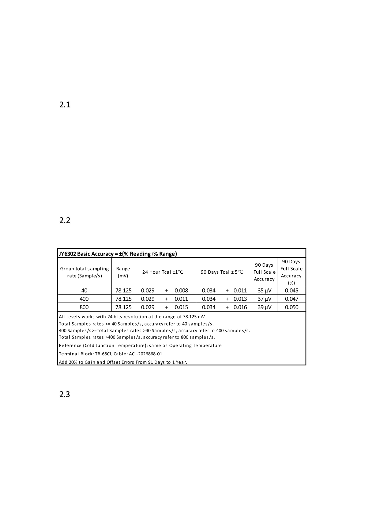
Basic Voltage Accuracy .................................................................................... 5
Temperature Drift Adjustment ........................................................................ 5
Example of Calculating Gain and Offset Errors ................................................6
3. Temperature Measurement Specifications ..........................................................6
Thermocouple Measurement Basics ............................................................... 7
Thermocouple Accuracy .................................................................................. 7
Temperature Measurement Accuracy by JY6302 ............................................9
Total Temperature Measurement Accuracy ..................................................11
Accuracy Not Listed ....................................................................................... 11
4. Additional Specifications ...................................................................................12
Input Characteristics ...................................................................................... 12
Timing and Trigger ......................................................................................... 13
Front Panel conections and Pinout Definition ...............................................13
Channel Groups ..............................................................................................15
Physical and Environment ..............................................................................15
5. Software ........................................................................................................... 16
System Requirements .................................................................................... 16
System Software ............................................................................................ 16
C# Programming Language ............................................................................ 17
C ++ Programming Language ......................................................................... 17
JY6302 Hardware Driver ................................................................................ 17
Install the SeeSharpTools from JYTEK ............................................................17
Running C# Programs in Linux ....................................................................... 18
6. Operating JY6302 Module ................................................................................. 19
Quick Start ......................................................................................................19
AI Operations ................................................................................................. 19
6.2.1 Channel Scan Sequence ...................................................................... 19

6.2.2 Sample Rates and Noise Reduction .................................................... 21
Cold-junction compensation ..........................................................................24
Open Thermocouple Detection ..................................................................... 25
Trigger Source ................................................................................................ 27
6.5.1 Immediate Trigger ...............................................................................27
6.5.2 Software Trigger ..................................................................................27
6.5.3 External Digital Trigger ........................................................................27
Trigger Mode ..................................................................................................30
6.6.1 Start Trigger ........................................................................................ 30
6.6.2 Reference Trigger ................................................................................32
6.6.3 Retrigger ..............................................................................................32
Learn by Example 6.6.2 and 6.6.3 ................................................................33
System Synchronization Interface(SSI)for PCIe Modules .........................36
DIP Switch in PCIe-6302 .................................................................................36
7. Calibration ........................................................................................................ 38
8. Using JY6302 in Other Software ........................................................................ 39
Python ............................................................................................................ 39
9. Appendix .......................................................................................................... 39
Connecting Thermocouple .............................................................................39
9.1.1 Voltage Bias .........................................................................................40
9.1.2 Thermocouple Simulator .................................................................... 40
Thermocouple Measurement Noise ..............................................................41
9.2.1 Common Mode Noise ......................................................................... 41
9.2.2 Normal Mode Noise ............................................................................42
9.2.3 Electrostatic Noise .............................................................................. 42
Influence of Thermocouple Type on Measurements .................................... 43
Thermocouple Installation Method ...............................................................44
10. About JYTEK .................................................................................................... 46
JYTEK China .................................................................................................. 46
JYTEK Korea and JYTEK in Other Countries ..................................................46
JYTEK Hardware Products ............................................................................ 46
JYTEK Software Platform ..............................................................................47
JYTEK Warranty and SupportServices ..........................................................47
11. Statement ....................................................................................................... 48

Figure 1 Voltage and Temerature Measuremets ............................................... 2
Figure 2 JYPEDIA Information ............................................................................. 3
Figure 3 TB- 68CJ terminal block. ........................................................................3
Figure 4 TB-68CJ Pin Defination ..........................................................................4
Figure 5 Thermocouple Temperature Measurement Principle ..........................7
Figure 6 PXIe/PCIe 6302 Front Panel ................................................................13
Figure 7 Typical channel scan sequence ...........................................................20
Figure 8 Random channel scan sequence .........................................................21
Figure 9 AI Continuous Raw Data Paraments ...................................................22
Figure 10 Continuous Raw Data Acquisition .................................................... 23
Figure 11 Terminal Block State Check .............................................................. 25
Figure 12 Open Thermocouple Detection ........................................................ 26
Figure 13 Rising and falling edges of digital signals ..........................................27
Figure 14 Digital Trigger Paraments ................................................................. 28
Figure 15 Digital Trigger Acquisition .................................................................29
Figure 16 Start Trigger mode ............................................................................30
Figure 17 AI Continuous Paraments ................................................................. 31
Figure 18 Signel Channel Continuous Acquisition .......................................... 31
Figure 19 Reference Trigger mode ................................................................... 32
Figure 20 Retrigger mode ................................................................................. 33
Figure 21 Retrigger Paraments ......................................................................... 34
Figure 22 Retrigger In Reference Trigger Mode ............................................... 35
Figure 23 Retrigger Complete State ................................................................. 35
Figure 24 SSI Connector in PCIe-6302 .............................................................. 36
Figure 25 DIP Switch in PCIe-6302 ....................................................................37
Figure 26 Themocouple connection ................................................................. 39
Figure 27 Ground loops generate common mode noise ..................................41
Figure 28 Magnetic field produces normal mode noise ...................................42
Figure 29 Electrostatic Noise Coupling into Thermocouples ............................43
Figure 30 Three Thermocouple Types .............................................................. 43
Table 1 Basic Voltage Accuracy ...........................................................................5
Table 2 Additional Accuracy Adjustment due to Temperature Drift ..................6
Table 3 Calculating Gain and Offset Errors .........................................................6
Table 4 Err1:Thermocouple Tolerance Class Information ..............................9
Table 5 Err2:Temperature Measurement Accuracy .....................................10
Table 6 Calculating Total Error ..........................................................................11

Table 7 Input Characteristics ............................................................................ 13
Table 8 Timing and Trigger Specification ..........................................................13
Table 9 Pinout defination ................................................................................. 14
Table 10 JY6302 channel groups .......................................................................15
Table 11 Physical and Environment ..................................................................15
Table 12 Supported Linux Versions .................................................................. 16
Table 13 SSI Connector Pin Assignment for PCIe-6302 .................................... 36
Table 14 Relationship between switch position and slot number ................... 37
Table 15 Comparison of different thermocouple types ................................... 44

PCIe/PXIe-6302 | jytek.com | 1
1. Introduction
This chapter presents the information how to use this manual and quick start if you
are already familiar with Microsoft Visual Studio and C# programming language.
Overview
JY6302 is a high-precision, high-resolution voltage and temperature measurement
module. It provides up to 32 channels of measurements and supports
R/S/B/J/T/E/K/N/C/A types of thermocouples, with input voltage range of ±78.125
mV and sample rate up to 800 Samples/sec. JY6302 has both PCIe and PXIe version.
Main Features
Up to 0.103% full scale accuracy
32 channels of measurements
Voltage range supported:±78.125 mV
Support R/S/B/J/T/E/K/N/C/A types of thermocouples
8 cold-junction compensation channels provided by 2 TB-68CJ terminal
blocks
Open Thermocouple Detection (OTD)
Onboard 128M sample FIFO buffer for analog input
DMA for analog input
24 bits resolution
Provide voltage (EMF value) to temperature (°C) conversion specified by the
standards
Digital and Software Trigger
Voltage and Temperature Measurements
Figure 1 shows how JY6302 is typically used to measure the temperature through
thermocouples. A thermocouple converts a temperature measurement to a voltage
which is measured by JY6302.

PCIe/PXIe-6302 | jytek.com | 2
Figure 1 Voltage and Temerature Measuremets
The accuracy and resolution of the temperature measurement are determined by
the those of thermocouples and JY6302.
Abbreviations
JY6302: JYTEK PCIe/PXIe/TXI/USB-6302
AI: Analog Input
ADC: Analog to Digital Conversion
PFI: Programmable Function Interface
CJ:Cold-Junction
CJC: Cold-Juntion Compensation
OTD: Open Thermocouple Detection
Th: Temperature at measuring junction
Tc: Temperature at cold junction also called the reference junction
Tcal: Board calibration temperature
JYPEDIA
JYPEDIA is an excel file, which contains JYTEK product information, pricing, inventory
information, drivers, software, technical support, knowledge base etc. You can
download a JYPEDIA excel file from our web www.jytek.com. JYTEK highly
recommends you use this file to obtain information from JYTEK.
1.4 Learn by Example

PCIe/PXIe-6302 | jytek.com | 3
Learn by Example is a unique feature in JYTEK product manual. in this manual. We
provide many sample programs for this device. Open JYPEDIA and search for JY6302
in the driver sheet, select JY6302_Examples.zip. This will lead you to download the
sample program for this device.
Figure 2 JYPEDIA Information
In a Learn by Example section, the sample program is in bold style such asWinform
AI Continuous; the property name in the sample program is also in bold style such as
SamplesToAcquire; the technical names used in the manual is in italic style such as
SampleRate. You can easily relate the property names in the example program with
the manual documentation.
To use Learn by Example, you should connect your JY6302 to a TB- 68CJ terminal
block, shown in Figure 3, through an ACL-2026868-01 cable.
Figure 3 TB- 68CJ terminal block.

PCIe/PXIe-6302 | jytek.com | 5
2. Voltage Measurement Specifications
This chapter provides the voltage accuracy specifications of JY6302.
Gain and Offset Errors
An instrument’s accuracy is defined by the gain and offset errors as follows:
Voltage Accuracy = Gain Error (% of reading) + Offset Error (% of range).
Equation 1 Gain and Offset Errors
It should be noted when the reading is close to zero, the gain error is very small and
negligible, the offset error is dominant; when the reading is getting close to the full
range, the gain error becomes more significant.
Basic Voltage Accuracy
The basic voltage measurement accuracy of JY6302 is shown in Table 1.
Table 1 Basic Voltage Accuracy
Temperature Drift Adjustment
If JY6302 operates outside the calibration temperature range, typically Tcal ±1°C,
the accuracy must be adjusted by Table 2. The entries are per degree C. For example,
if the operating temperature is 2°C outside the calibration temperature, the
adjustment numbers from the table need to be multiplied by 2. The gain and offset

PCIe/PXIe-6302 | jytek.com | 6
error adjustment should then be added to the basic gain and offset errors in Table 1
Basic Voltage Accuracy to obtain the accuracy after the temperature drift.
Table 2 Additional Accuracy Adjustment due to Temperature Drift
Example of Calculating Gain and Offset Errors
Table 3 shows two examples of calculating the total gain and offset errors. The first
one has a reading value of 2mV, while the second one has a reading value of 60 mV.
For the 2mV reading value, the total gain error is 1.1 μV, while for the 60 mV reading
value, the gain error is 33.1 μV, 30 times bigger than the first one. The offset errors
for both reading values are the same 12.6 μV.
Table 3 Calculating Gain and Offset Errors
3. Temperature Measurement Specifications

PCIe/PXIe-6302 | jytek.com | 7
The accuracy of the temperature measurement depends on the thermocouple, the
connectors, the terminal block, and the measuring device. This chapter provides the
temperature measurement accuracy specifications by JY6302 and specified terminal
block only. The effect of the thermocouple is not included.
Thermocouple Measurement Basics
A Thermocouple temperature measurement utilizes the "Seebeck effect", and its
basic measurement principle is shown in the Figure 5 Thermocouple Temperature
Measurement Principle.
Figure 5 Thermocouple Temperature Measurement Principle
Two different types of metals A and B are connected to each other, and the
temperature difference between the temperature measuring contact Th (Metal
Junction) and the reference contact Tc (Thermocouple Display Instrument Contact) is
used to generate the corresponding voltage, also called the Electromotive Force
(EMF)in the standards. This voltage is measured by JY6302 and is then converted
the temperature values using a conversion formula defiend by the standard.
Thermocouple Accuracy
A thermocouple has its own accuracy, also called the error tolerance in many
international standards. Table 4 shows the accuracies of common thermocouple
types by two commonly used standards. Using the K-type as an example. Each K-type
thermocouple falls into one of the three classes. The maximum accuracy of class 1 of
the K-type thermocouple is ±1.5°C or ±(0.004*|T|), whichever is bigger. T is the
measured temperature value in °C.

PCIe/PXIe-6302 | jytek.com | 9
Table 4 Err1:Thermocouple Tolerance Class Information
The accuracies given by Table 4 are valid for thermocouple material only. It is
important that users verify the accuracy of the thermocouple from the
thermocouple manufacturer.
Temperature Measurement Accuracy by JY6302
A thermocouple converts a temperature reading to a voltage which is then measured
by JY6302. The standard provides the conversion formula for different
thermocouples and for different temperature ranges. Table 5 shows the
temperature measurement accuracy using JY6302 for each type and each range of
thermocouple. The operating conditions are also listed in the table.

PCIe/PXIe-6302 | jytek.com | 10
Table 5 Err2:Temperature Measurement Accuracy
It is important to note that the accuracy data only includes the measurement errors
by JY6302, using the specified ACL-2026868-01 cable and the TB-68CJ termial block.
It does not include the errors of the thermocouple itself. To get the total
measurement accuracy, users must check with thermocouple error specifications

PCIe/PXIe-6302 | jytek.com | 11
from the thermocouple manufacturer. Section 3.4 provides the information how to
calculate the total accuracy.
Total Temperature Measurement Accuracy
The total temperature measurement accuracy consists of the errors due to the
thermocouple and measurement errors by JY6302 as shown in Figure 5. It can be
calculated by:
Total Accuracy Err =
Err1is the thermocouple error from Table 4 of Section 3.2. Err2is the temperature
measurement accuracy from Table 5 of Section 3.3.
Table 6 shows two calculations for the total accuracies when using a class 1 K-type
thermocouple to measure 100 ºC and 800 ºC temperatures with 40 Sample/s
sample rate. The two temperatures fall into different range. Hence the temperature
measurement errors by JY6302 are different.
Table 6 Calculating Total Error
Accuracy Not Listed
Table 5 lists the temperature measurement accuracies for most common
applications. There are other factors affecting the measurement accuracy. Most
important factors are 1) when the operating temperature is beyond the Tcal ±1°C
range, and 2) when the cold junction reference temperature are different from the
operating temperature as assumed in Table 5. It is not possible to list all these
accuracies. JYTEK provides a utility in JY6302 C# example to calculate the accuracy
Table of contents
Other JYTEK Control Unit manuals
Popular Control Unit manuals by other brands

Vimar
Vimar by-me Eikon 20546 manual

Leadshine Technology Co.
Leadshine Technology Co. EM870S user manual

Azbil
Azbil Actival VY5199J Series Specifications and Instructions

O&O
O&O LOG-BC Installation and operation manual

YOKOGAWA
YOKOGAWA WE7231 user manual

Flowserve
Flowserve Valtek CavControl Trim Installation, operation & maintenance instructions