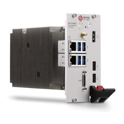
JYTEK PXIe-63935 User manual

PXIe-63935
PXIe Express Embedded Controller
User’s Manual
Manual Rev.: 1.00
Revision Date: Jul. 16, 2016

I
Getting Service
Contact us should you require any service or assistance.
SHANGHAI JYTEK Co., Ltd.
Web site: hp://www.jytek.com
Address: 300 Fang Chun Rd., Zhangjiang Hi-Tech Park, Pudong New Area, Shanghai, 201203
China
Tel: +86-21-5047-5899
Fax: +86-21-5047-5899
Email: [email protected]
Addional informaon, aids, and ps that help users perform tasks
Informaon to prevent minor physical injury, component damage, data loss,
and/or program corrupon when trying to complete a task.
Informaon to prevent serious physical injury, component damage, data loss,and/
or program corrupon when trying to complete a specic task.

II
Table of Contents
Geng Service �������������������������������������������������������������������������������������������������� I
1 Introducon������������������������������������������������������������������������������������������������ 1
1�1 Features ��������������������������������������������������������������������������������������������� 1
1.2 Specicaons ������������������������������������������������������������������������������������� 2
1�3 Front Panel I/O & Indicators ��������������������������������������������������������������� 5
1�3�1 PXIe Trigger Connector ������������������������������������������������������������ 6
1�3�2 DisplayPort Connectors ����������������������������������������������������������� 6
1�3�3 GPIB Connector����������������������������������������������������������������������� 7
1.3.4 Reset Buon ��������������������������������������������������������������������������� 8
1�3�5 LED Indicators ������������������������������������������������������������������������� 8
1�3�6 USB 2�0 Ports �������������������������������������������������������������������������� 9
1�3�7 Gigabit Ethernet Ports������������������������������������������������������������10
1�3�8 COM Port �������������������������������������������������������������������������������11
1�3�9 USB 3�0 Ports �������������������������������������������������������������������������11
1.3.10 Onboard Connecons and Sengs���������������������������������������12
2 Geng Started�������������������������������������������������������������������������������������������13
2�1 Package Contents ������������������������������������������������������������������������������13
2.2 Operang System Installaon������������������������������������������������������������13
2.2.1 Driver Installaon ������������������������������������������������������������������14
2.2.2 Installaon Environment ��������������������������������������������������������14
2�2�3 Installing the PXIe-63935��������������������������������������������������������15
2�2�4 Replacing the Hard Drive or Solid State Drive �������������������������16
2.2.5 Replacing the Baery Backup�������������������������������������������������16
2�2�6 Clearing CMOS �����������������������������������������������������������������������17
2.2.7 Iniang Backup BIOS Flash ���������������������������������������������������17
Appendix A - PXIe Trigger I/O Funcon Reference��������������������������������������������18
A�1 Data Types ����������������������������������������������������������������������������������������18
A.2 Funcon Library��������������������������������������������������������������������������������19
A�2�1 TRIG_Init �������������������������������������������������������������������������������19
A�2�2 TRIG_Close ����������������������������������������������������������������������������19
A.2.3 TRIG_SetSoTrg���������������������������������������������������������������������20
A�2�4 TRIG_Trigger_Route ���������������������������������������������������������������20
A�2�5 TRIG_Trigger_Clear ����������������������������������������������������������������22
A.2.6 TRIG_GetSoTrg ��������������������������������������������������������������������22
A�2�7 TRIG_Trigger_Route_Query����������������������������������������������������23
A�2�8 TRIG_GetDriverRevision���������������������������������������������������������24
Appendix B BIOS Setup�����������������������������������������������������������������������������������26
B.1 Starng the BIOS�������������������������������������������������������������������������������26
B�2 Main Setup ���������������������������������������������������������������������������������������27

III
B�3 Advanced Setup ��������������������������������������������������������������������������������27
B�4 Boot Setup ����������������������������������������������������������������������������������������28
B�5 Security Setup�����������������������������������������������������������������������������������28
B�6 Save & Exit Setup ������������������������������������������������������������������������������29
Important Safety Instrucons ��������������������������������������������������������������������������30

IV
List of Tables
Table 1-1: Display Port Pin Assignment ������������������������������������������������������������ 7
Table 1-2: GPIB Pin Descripon������������������������������������������������������������������������ 8
Table 1-3: LED Indicator Legend ����������������������������������������������������������������������� 9
Table 1-4: USB 2.0 Port Pin Assignment�����������������������������������������������������������10
Table 1-5: PXIe-63935 Ethernet Port Pin Assignments �������������������������������������10
Table 1-6: D-Sub 9p COM Port Signal Funcons�����������������������������������������������11
Table 1-7: Onboard Conguraon Legend2 �����������������������������������������������������12
Table B-1: BIOS Hot Key Funcons ������������������������������������������������������������������27
Table B-2: BIOS Main Setup Menu ������������������������������������������������������������������27
Table B-3: BIOS Advanced Setup Menu �����������������������������������������������������������28
Table B-4: BIOS Boot Setup Menu �������������������������������������������������������������������28
Table B-5: BIOS Security Setup Menu��������������������������������������������������������������29

V
List of Figures
Figure 1-1: PXIe-63935 Funconal Block Diagram���������������������������������������������� 2
Figure 1-2: Front Panel�������������������������������������������������������������������������������������� 5
Figure 1-3: PXIe Trigger SMB Jack���������������������������������������������������������������������� 6
Figure 1-4: LED Indicators ��������������������������������������������������������������������������������� 9
Figure 1-5: COM Port ���������������������������������������������������������������������������������������11
Figure 1-6: PXIe-63935 Onboard Conguraon ������������������������������������������������12

1
1 Introduction
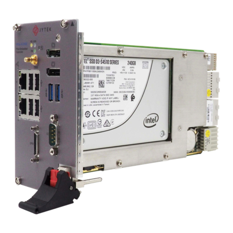
The JYTEK PXIe-63935 PXI Express embedded controller, based on the Intel® Celeron®
2000E 2.2GHz processor, pairs superior performance with an unprecedented price point.
Specically conceived for hybrid PXI Express-based tesng systems, the JYTEK PXIe-63935
delivers a rugged and stable plaorm for a wide variety of tesng and measurement
applicaons.
The PXIe-63935 provides ample interface exibility, including two DisplayPort connectors,
allowing connecon to two monitors, dual USB 3.0 connecons for high speed peripheral
devices, dual Gigabit Ethernet ports with one for LAN connecon and the other for controlling
LXI instruments, four USB 2.0 ports for peripheral devices and USB instrument control, a
Micro-D GPIB connector for GPIB instrument connecon, and one RS-232/422/485 DSUB9
connector for hybrid PXI-based tesng systems control.
JYTEK’s PXIe-63935 signicantly reduces maintenance burdens with easily replaceable
baery and upgradable storage and SODIMM modules. Backup BIOS also eases recovery in
the event of a main BIOS crash.
Memory addressing over 4GB is OS-dependent, such that a 32-bit operang system
may be unable to address memory space over 4GB. To fully ulize memory, 64-bit
operang systems are required.
1�1 Features
• Ideal balance between performance and price point
• Intel® Celeron® 2000E 2.2GHz processor
• Dual channel DDR3L SODIMM up to 16GB 1600MHz
• 8 GB/s maximum system throughput
• Dual display port support
• 2.5” HDD or SSD support
• SATA 3Gb/s
• AHCI support
• Integrated I/O
◦Dual Gigabit Ethernet ports
◦ Two USB 3.0 Ports
◦ Four USB 2.0 Ports
◦ Built-in GPIB (IEEE488) controller
◦Dual DisplayPort connector
◦ One COM port (D-sub9 serial)
◦ Trigger I/O for advanced PXI™ trigger funcons
• Dual BIOS support for backup

2
1�2 Specifications
Figure 1-1: PXIe-63935 Functional Block Diagram
Processor
• Intel® Celeron® 2000E 2.20GHz processor for maximum compung power
• DMI (Direct Media Interface) with 5 GT/s of bandwidth in each direcon
Chipset
Mobile Intel® HM86
Memory
• 2x standard 204-pin DDR3L SODIMM sockets
• Support for 1333/1600MHz RAM up to 16 GB total
• Support for non-ECC unbuered memory
Front Panel
Connectors
GPIB
USB 2.0 x4
GbE
GbE
COM port
SMB
DisplayPort x2
USB 3.0 x2
GPIBGPIB controller
GPIB controller
I210
Digital
Display I/F
USB 2.0
USB 3.0
SATA
LPC-COM Port
Trigger SignalTrigger Bus
Controller
Trigger Bus
Gen2 2Links x8 +
x16
Gen2 4Links x4
PXIe Connector
PCIe Gen2.0
48 Ianes
swtich
LPC PCIe x1
PCH
HM86
GbE PHY
I217
PCIe x1
Intel FDI DMI
PCIe Gen2 x16
DDR3
1600MHz
DDR3
1600MHz
PCIe x1
PCIe x1
Channel A
SODIMM
Channel B
SODIMM
Haswell Intel
Celeron 2000E
2.5” SATA
Interposer
Board
GbE I/F
GbE I/F
or

3
The externally accessible SODIMM socket can accept replacement DDR3L DRAM
DIMM modules. PXIe-63935 specicaons and stability guarantees are only
supported when JYTEK-provided DDR3L DRAM DIMM modules are used.
Video
• DisplayPort supports up to 3840x 2160 @60Hz resoluon
• DVI (with passive DisplayPort-to-DVI adapter) supports resoluons up to 1920 x 1200
@60Hz
DisplayPort adapters for other standards are supported, with maximum available
resoluon dependent on the adapter chosen
Hard Drive
Built-in 2.5” 500GB SATA hard drive or 240GB SATA solid state hard drive.
I/O Connecvity
Dual Gigabit Ethernet through two RJ-45 connectors with speed/ link/acve LED indicators
on the front panel, with both supporng Wake on LAN.
USB
Four USB 2.0 and two USB 3.0 ports on the front panel.
COM port
One RS-232/422/485 D-SUB9 connector.
GPIB
Onboard IEEE488 GPIB controller through Micro-D 25-pin connector on the front panel.
Trigger I/O
One SMB connector on the front panel to route an external trigger signal to/from PXIe
trigger bus
Dimensions (3U PXI module)
3U/4-slot PXI standard.
80.94 W x 128.7 H x 212.9 D mm (3.15 x 5.01 x 8.3 in.)
Weight
1.0kg (exclusive of packaging)
Environmental
Operang temperature with SSD 0 to 55°C
Operang temperature with HDD 0 to 50°C
Storage temperature -20 to 70°C
Relave humidity , non-condensing 5 to 95%

4
Shock and Vibraon
Funconal shock 30 G, half-sine, 11 ms pulse duraon
Random vibraon:
• Operang 5 to 500 Hz, 0.21 Grms, 3 axes
• Non-operang 5 to 500 Hz, 2.46 Grms, 3 axes
Environmental & Shock and Vibraon values are only guaranteed with use of an
JYTEK-provided SSD/HDD
Cercaon
Electromagnec compability:
• EMC/EMI: CE, FCC Class A
• CE Compliance EN 61326-1
The PXIe-63935 meets the essenal requirements of applicable European Direcves.
Power Requirements
Voltage Rail +3�3V +5V +12V Total (W)
Maximum power consumpon 3.3 38 1.2 42.5
Idle power consumpon 3.3 22.5 1.2 27

5
1�3 Front Panel I/O & Indicators
Figure 1-2: Front Panel
PXIe-63935

6
The PXIe-63935 provides the following I/O and indicators, as labeled on the front panel.
• PXI Trigger Connector (SMB jack)
• 2X DisplayPort Connectors
• GPIB Connector (Micro D-Sub 25P)
• Reset Buon
• LED indicators
• 4X Type-A USB 2.0
• connectors
• 2X Gigabit Ethernet
• 2X USB 3.0
• 1X COM port (D-sub9 serial)
1�3�1 PXIe Trigger Connector
Trigger
Ground
Figure 1-3: PXIe Trigger SMB Jack
The PXIe trigger connector is a SMB jack, used to route external trigger signals to or from
the PXIe backplane. Trigger signals are TTL-compable and edge sensive. The PXIe-63935
provides four trigger roung modes from/to the PXIe trigger connector to synchronize PXIe
modules, including
• From a selected trigger bus line to PXIe trigger connector
• From the PXIe trigger connector to a selected trigger bus line
• From soware trigger to a selected trigger bus line
• From soware trigger to PXIe trigger connector
All trigger modes are programmable by the provided driver. Please refer to Secon A: PXIe
Trigger I/O Funcon Reference for further informaon.
1�3�2 DisplayPort Connectors
Supporng monitor connecon, with, if connecng to VGA/DVI/ HDMI monitors, installaon
of requisite adapters required. Dual display funcon is also supported

7
.
19 1
2
20
Pin Signal Pin Signal
1 CN_DDPx0+ 11 GND
2 GND 12 CN_DDPx3-
3CN_DDPx0- 13 CN_DDPx_AUX_SEL
4CN_DDPx1+ 14 CN_DDPx_CONFIG2
5GND 15 CN_DDPx_AUX+
6CN_DDPx1- 16 GND
7CN_DDPx2+ 17 CN_DDPx_AUX-
8 GND 18 CN_DDPx_HPD
9 CN_DDPx2- 19 GND
10 CN_DDPx3+ 20 +V3.3_DDPx_PWR
Table 1-1: Display Port Pin Assignment
1�3�3 GPIB Connector
The GPIB connector on PXIe-63935 is a micro D-sub 25P connector, controlling external
bench-top instruments. Connecon to other instruments requires the ACL-IEEE488-MD1-A
cable. The on-board GPIB controller provides:
• Full compability with IEEE 488 standard
• Up to 1.5MB/s data transfer rates
• Onboard 2 KB FIFO for read/write operaons
• Driver APIs compable with NI-488.2 driver soware
• Connecon with up to 14 instruments

8
1 13
14 25
Pin Signal Descripon Pin Signal Descripon
1DIO1# GPIB Data 1 14 DIO5# GPIB Data 5
2DIO2# GPIB Data 2 15 DIO6# GPIB Data 6
3DIO3# GPIB Data 3 16 DIO7# GPIB Data 7
4 DIO4# GPIB Data 4 17 DIO8# GPIB Data 8
5EOI End Or Idenfy 18 REN Remote Enable
6DAV Data Valid 19 Ground Signal Ground
7NRFD Not Ready For Data 20 Ground Signal Ground
8NDAC No Data Accepted 21 Ground Signal Ground
9IFC Interface Clear 22 Ground Signal Ground
10 SRQ Service Request 23 Ground Signal Ground
11 ATN Aenon 24 Ground Signal Ground
12 Chassis
Ground
Chassis Ground 25 Ground Signal Ground
13 Ground Signal Ground
Table 1-2: GPIB Pin Descripon
1�3�4 Reset Button
The reset buon, acvated by inseron of any pin-like implement, executes a hard reset for
the PXIe-63935.
1�3�5 LED Indicators
Four LED indicators on the front panel indicate operaonal status of the PXIe-63935, as
follows.

9
Figure 1-4: LED Indicators
LED Color Descripon
PW Green Indicates system power, remaining lit when the system
boots normally and main power supply is funconing
HD Yellow Indicates operang state of the HDD or SSD, ashing during
access to or acvity on the SATA HDD
USR Blue User-programmable LED indicator
Table 1-3: LED Indicator Legend
In the event of malfuncon, clear the CMOS (See “Clearing CMOS” on page 17.) and
reboot the system. If the system fails to respond properly, please contact JYTEK for
assistance.
1�3�6 USB 2�0 Ports
The PXIe-63935 provides four USB 2.0 ports via USB Type A connectors on the front panel,
all compable with hi-speed, full-speed and low-speed USB devices. Supported boot
devices include USB ash drive, USB oppy, USB CD-ROM, and others, with boot priority
and device sengs congurable congured in BIOS. See “Boot Setup” on page 28. for more
informaon.

10
Pin Signal
1/5 Power 5V
2/6 USB Data-
3/7 USB Data +
4/8 Ground
Table 1-4: USB 2.0 Port Pin Assignment
1�3�7 Gigabit Ethernet Ports
Dual Gigabit Ethernet connecon is provided on the PXIe-63935 front panel.
Pin 1000Base-T Signal 100/10Base-T Signal
1 MDI0+ TX+
2MDI0- TX-
3 MDI1+ RX+
4MDI2+ Reserved
5 MDI2- Reserved
6MDI1- RX-
7MDI3+ Reserved
8MDI3- Reserved
Table 1-5: PXIe-63935 Ethernet Port Pin Assignments
The Ethernet ports each include two LED indicators, one Acve/ Link indicator and one
Speed indicator, funconing as follows.
LED Status Description
Active/Link
(Yellow)
Off Ethernet port is disconnected
On Ethernet port is connected with no
data transmission
Flashing Ethernet port is connected with
data transmitted/received
Speed
(Green/
Orange)
Off 10 Mbps
Green 100 Mbps
Orange 1000 Mbps

11
1�3�8 COM Port
The COM port with D-sub 9P connectors supports RS-232/RS422/RS-485 according to BIOS
seng.
1 5
69
Figure 1-5: COM Port
Pin Signal
RS-232 RS-422 RS-485
1DCD# TXD422- 485DATA-
2 RXD TXD422+ 485DATA+
3 TXD RXD422+ N/S
4 DTR# RXD422- N/S
5GND N/S N/S
6DSR# N/S N/S
7RTS# N/S N/S
8CTS# N/S N/S
9 RI# N/S N/S
Table 1-6: D-Sub 9p COM Port Signal Funcons
1�3�9 USB 3�0 Ports
The PXIe-63935 provides two Type A USB 3.0 ports on the front panel, supporng
SuperSpeed, Hi-Speed, full-speed, and lowspeed transmission for downstream. Mulple
boot devices, including USB ash, USB external HD, and USB CD-ROM drives are supported,
with boot priority congured in BIOS.
While the USB 3.0 ports allow boot from CD-ROM, OS installaon via CD-ROM is not
supported

12
1�3�10 Onboard Connections and Settings
Figure 1-6: PXIe-63935 Onboard Configuration
A SATA Connector
B Clear CMOS switch
CSystem Baery
Table 1-7: Onboard Conguraon Legend2

13
2 Getting Started
This chapter describes procedures for installing the PXIe-63935 and making preparaons
for its operaon, including hardware and soware setup. Please note that the PXIe-63935
is shipped with RAM and HDD or SSD preinstalled. Please contact JYTEK if there are any
problems during the installaon.
Diagrams and illustrated equipment are for reference only.
Actual system conguraon and specicaons may vary.
2�1 Package Contents
Before beginning, check the package contents for any damage and ensure that the following
items are included:
• PXIe-63935 Controller (equipped with RAM and HDD or SSD)
• DisplayPort-to-DVI adapter
• JYTEK All-in-one USB Flash Driver
If any of these items are missing or damaged, contact JYTEK or the dealer from whom you
purchased the product. Save the shipping materials and carton in case you want to ship or
store the product in the future.
Do not install or apply power to equipment that is damaged or missing
components. Retain the shipping carton and packing materials for inspecon.
Please contact your JYTEK immediately for assistance and obtain authorizaon
before returning any product.
2.2 Operating System Installation
For more detailed informaon about the operang system, refer to the documentaon
provided by the operang system manufacturer. Preferred/supported operang systems
for PXIe-63935 are:
• Windows 7 32/64-bit
• For other OS support, please contact JYTEK
Most operang systems require inial installaon from a hard drive, oppy drive, or CD-
ROM drive. The PXIe-63935 controller supports USB CD-ROM drive, USB ash disk, USB
external hard drive, or a USB oppy drive as the rst boot device. See “Boot Setup” on page
28. for informaon about seng the boot devices. These devices should be congured,
installed, and tested with the supplied drivers before aempng to load the new operang
system.

14
Read the release notes and installaon documentaon provided by the operang
system vendor. Be sure to read all the README les or documents provided on the
distribuon disks, as these typically note documentaon discrepancies or
compability problems.
1. Select the appropriate boot device order from the BIOS Boot Setup Menu based on
the OS installaon media used. For example, if the OS is distributed on a bootable
installaon CD, select USB CD-ROM as the rst boot device and reboot the system
with the installaon CD in the USB CD-ROM drive
2. Proceed with the OS installaon as directed and be sureto select appropriate device
types if prompted. Refer to the appropriate hardware manuals for specic device
types and compability modes of JYTEK PXIe products.
3. When installaon is complete, reboot the system and sehe boot device order in the
SETUP boot menu accordingly.
2�2�1 Driver Installation
Download requisite drivers, as follows, from hp://www.JYTEK.com.
1. Fully install Windows, which contains most standard I/Odevice drivers
2. Install the chipset driver
3. Install the graphic driver
4. Install the Ethernet driver
5. Install the GPIB driver
6. Install the management engine driver
7. Install the PXIe trigger driver
8. Install the USB 3.0 driver
2.2.2 Installation Environment
When preparing to install any equipment described in this manual, see “Chapter: Important
Safety Instrucons”.
Only install equipment in well lit areas on at, sturdy surfaces with access to basic tools
such as at- and cross-head screwdrivers, preferably with magnec heads as screws and
standos are small and easily misplaced.
Recommended Installaon Tools
• Phillips (cross-head) screwdriver
• Flat-head screwdriver
• An-stac wrist strap
• An-stac mat
JYTEK PXIe-63935 system controllers are electrostacally sensive and can be easily
Table of contents
Other JYTEK Controllers manuals
Popular Controllers manuals by other brands

Controlsoft
Controlsoft AC-3100 installation instructions

Semtech
Semtech IOT8EUSBREF-1 user guide

maxon motor
maxon motor EPOS2 70/10 Hardware reference

Gefa
Gefa Automax SuperNova Series Installation, operating, & maintenance instructions

Circutor
Circutor CDP series Application notes

zeeltronic
zeeltronic VCDI-04 user manual