Könner & Söhnen KS 4100iE User manual

KS 4100iE
KS 4100iEG
KS 8100iE
KS 8100iEG
KS 8100iE ATSR
KS 8100iEG ATSR
Inverter Generator
Inverter Generator
in Soundproof Housing
EN
Please, read this manual
carefully before use! Owner’s Manual
KS 2000i S
KS 2000iG S
KS 4000iE S
KS 4000iEG S

KS 4100iE
KS 4100iEG
KS 8100iE
KS 8100iEG
KS 8100iE ATSR
KS 8100iEG ATSR
Inverter Generator
Inverter Generator
in Soundproof Housing
Please, read this manual
carefully before use! Owner’s Manual
KS 2000i S
KS 2000iG S
KS 4000iE S
KS 4000iEG S
EN

INTRODUCTION
SAFETY INFORMATION 1
Thank you for your purchase of Könner & Söhnen products. This manual contains a brief description of
safety, use and debugging. More information can be found on the ocial manufacturer’s website in the
support section: ks-power.de/betriebsanleitungen.
You can also go to the support section and download the full version of the manual by scanning the QR
code, or on the website of the ocial importer of Könner & Söhnen products: www.ks-power.de/en.
Manufacturer reserves the right to make alterations into the generators, which may not be reected in this
manual. Pictures and photos of the product may vary from its actual appearance. At the end of this manual,
You may nd contact information which you are free to use in case of any issues occurrence.
All data, specied in this operation manual is the most up to date for the moment of its publishing. The
current list of service centers you can nd at the website of ocial importer: www.ks-power.de/en.
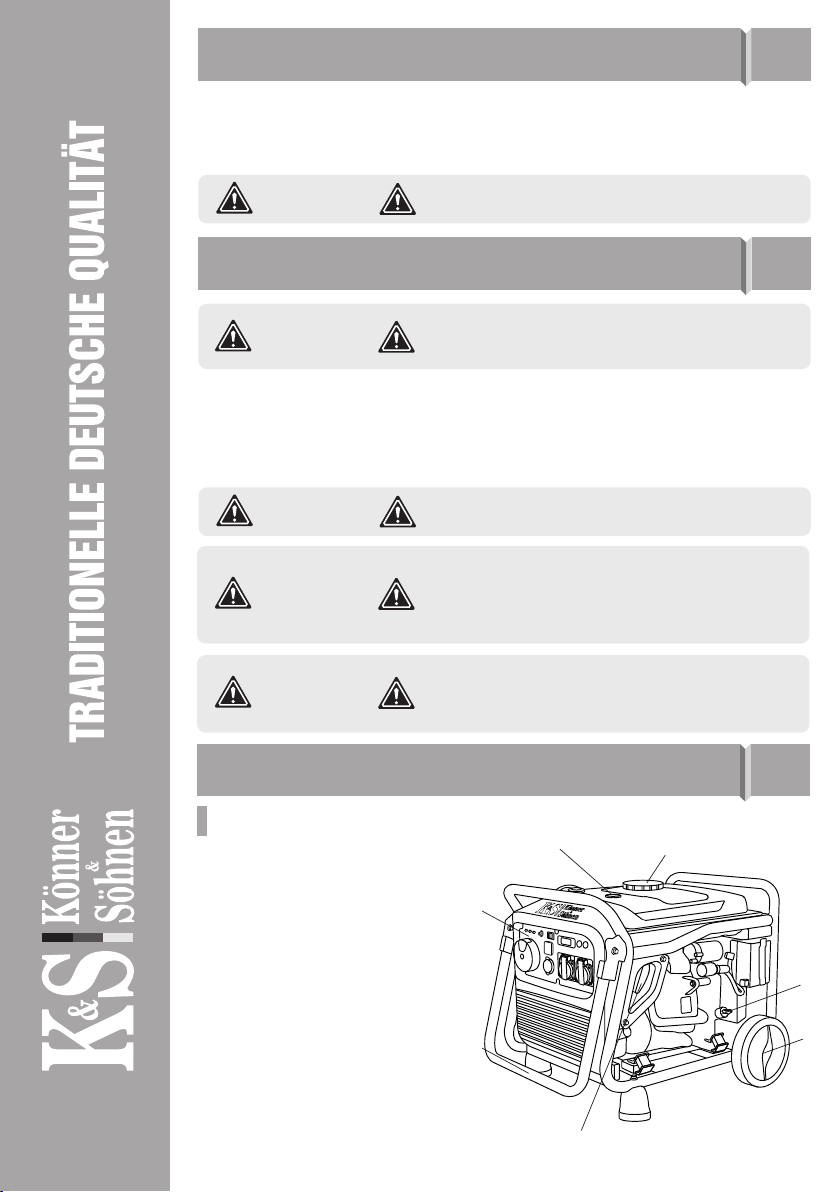
Do not use the generator in rooms with poor ventilation or in conditions of excessive humidity. Do not
place the generator in water or on moist soil. Do not expose the generator to rain, snow, as well as to direct
sunlight for a long time. Place the generator on a at, hard surface, away from ammable liquids/gases
(at a minimum distance of 1 m). Keep unauthorized persons, children, and animals away from work area.
Wear safety shoes and gloves.
We care about the environment, therefore, we consider it expedient to saveWe care about the environment, therefore, we consider it expedient to save
paper and leave in print a short description of the most important sections.paper and leave in print a short description of the most important sections.
Be sure to read the full version of the manual before
getting started!
Failure to follow the recommendations marked with this
sign may lead to serious injury or death of the operator
or third parties.
Useful information while operating the machine.
ATTENTION – DANGER!
IMPORTANT!
ELECTRICAL SAFETY 1.1
The generator produces electricity that may lead to an electric shock while neglecting compliance regulations.
All connecting the generator to the network must be made by certied electrician in accordance with all elec-
trical rules and regulations. Connect the generator to the protective ground before operation. Wires with
damaged or spoiled insulation should be replaced. You should also replace worn, damaged or rusty contacts.
The device generates electricity. Follow safety precautions
to avoid electric shock.
During operation of the engine, the tiller allocates
exhaust gases CO2that can cause poisoning. Do not use
the device in closed, badly ventilated areas
Using device for other purposes deprives the right for
free warranty.
ATTENTION – DANGER!
ATTENTION – DANGER!
IMPORTANT!
Be careful. Do not operate the generator, if you are tired,
under the inuence of drugs or alcohol. Inattention may
cause a serious injury.
ATTENTION – DANGER!
www.ks-power.de/en |302

PRECAUTIONS WHEN WORKING WITH
GASOLINE GENERATOR 1.2
Do not start the generator operation upon presence of electric load! Disconnect the load before you stop
the engine. Only unleaded gasoline is recommended for the generator. It is forbidden to use
kerosene or other fuel types. Before running the generator, it is necessary to dene the place and means of
its emergency stop. Do not refuel the running generator.
Fuel contaminates the land and groundwater. Do not
allow the leaking gasoline from the tank!
ATTENTION – DANGER!
MAIN OVERVIEW 2
2
3
4
1
6
7
5
MODELS KS 4100MODELS KS 4100iiE, KS 8100E, KS 8100iiE, KS 4100E, KS 4100iiEG, KS 8100EG, KS 8100iiEG ATSR, KS 8100EG ATSR, KS 8100iiE ATSR, KS 8100E ATSR, KS 8100iiEGEG
1. Fuel tank cap
2. Fuel level indicator
3. Control panel
4. Carrying handles
5. Manual starter
(only for models KS 4100iE, KS 4100iEG)
6. Transport wheels
7. Oil-depth gage
PRECAUTIONS WHEN WORKING WITH HYBRID GENERATOR 1.3
Do not start the generator operation upon presence of electric load! Before usage make sure, that all the
hoses are connected properly. In case of gas leakage, stop the gas ow from the source to generator and
ventilate the room as soon as possible. For stopping gas powered engine: disconnect all the connected de-
vices rst, then close the gas valve, then turn o the engine. After that set the starter switch to OFF position
and turn o the gas supply valve.
Do not allow sparks near gas powered generetor during
its work
ATTENTION - DANGER!
For dual fuel models, only propane-butane mixture for
cars (LPG) can be used as gas! It is forbidden to use any
other gas!
IMPORTANT!
It is forbidden to use the generator using LPG as fuel in
the mode of automatic start of ATS unit! It is dangerous
to leave the connected LPG cylinder open in the standby
mode, a gas leak can occur, which can lead to an explo-
sion!
ATTENTION - DANGER!
Pay attention! Usage of gasoline together with liqueed
gas is forbidden! When you operate using gasoline, you
must stop LPG supply. When you operate generator
using LPG - you must stop gasoline supply.
ATTENTION - DANGER!
1. Multifunctional engine switch
(except for dual-fuel models)
2. Oil level indicator
3. Overload indicator
4. Voltage indicator
5. Reset button
6. 12V DC fuse
7. Economy mode switch (ЕCОN) www.ks-power.de/en |303

1. 2 USB-Outputs
2. Economy mode switch (ЕCОN)
3. LED display
4. 1x16А AC outlet
5. Ground terminal
6. Reset button
7. Generator parallel socket
MODELS KS 4000MODELS KS 4000iiE S, KS 4100E S, KS 4100iiEGEG
MODELS KS 2000MODELS KS 2000iiS, KS 2000S, KS 2000iiG SG S
1. Fuel tank cap air vent
2. Carrying handles
3. Control panel
4. Manual starter
5. Air choke (для моделі KS 2000i S)
Fuel switch for model KS 2000iG S
Model KS 2000iG S has an air choke located on
its control panel.
6. Maintenance cover
(on the other side of the generator)
1. Fuel tank cap
2. Carrying handles
3. Control panel
4. Manual starter
5. Transport wheels
6. Maintenance cover
7. Multifunction engine switch
(For KS 4100iE G - fuel type switch. Engine switch
and air choke are located on the control panel)
3
4
2
1
5
54
6
7
3
21
761
2 3 4
5
6
Manufacturer reserves the right to make changes and/or
improvements in design, components set and technical
attributes without notice and without incurring
obligation. The pictures in this manual are schematical
and may not match the parameters of original product.
IMPORTANT!
2
1
9
10
111213
3 4 5 6 78
8. LED display
9. Generator parallel socket (except
for KS 8100 model modifications)
10. Ground terminal
11. 2x16А AC outlets (for KS 8100
model modifications,
sockets 1*16A, 1*32A)
12. 12V/8.3A DC outlet
(except for dual-fuel models)
13. 2 USB-Outputs
14. For LPG/gasoline models, the control panel has an
air choke (except for KS 8100iEG ATSR, KS 8100iEG) and a fuel switch. Use the start button instead of the
multifunction engine switch or engine start key.
15. Models KS 8100iEG ATSR and KS 8100iE ATSR use a control panel with an ATS (Automatic Transfer
Switch) output.
www.ks-power.de/en |304

1. 2 USB-Outputs
2. Economy mode switch (ЕCОN)
3. LED display with oil level indicator, overload indicator,
voltage indicator
4. 12V DC fuse
5. 2x16А AC outlets
6. Ground terminal
7. Generator parallel socket
8. Reset button
9. 12V/8A DC outlet (except for KS 4100iEG model)
3
78 691
542
Model KS 2000i S KS 2000iG S KS 4000iE S KS 4000iEG S
Voltage, V 230
Maximum power, kW 2.0 2.0* 4.0 4.0*
Nominal power, kW 1.8 1.8* 3.5 3.5*
Frequency, Hz 50
Current, A (max.) 8.7 8.7 17.4 17.4
Outlets 1*16A 1*16A 2*16A 2*16A
Engine start manual manual manual/electro manual/electro
Fuel tank volume, l 4 4 12 12
LED display voltage, frequency, working hours multifunctional**
Noise level Lpa (7m)/Lwa, dB 62/87 62/87 66/91 66/91
Output 12V, A - - 12V/8,3A -
USB-Outputs 5V/1A
5V/2.1A -5V/1A
5V/2.1A
5V/1A
5V/2.1A
Engine model KS 100i KS 100i KS 240i KS 240i
Engine volume, cm379.7 79.7 223 223
Engine type gasoline, 4 stroke cycle
engine
LPG/gasoline 4 stroke
cycle engine
gasoline,
4 stroke cycle engine
LPG/gasoline 4 stroke
cycle engine
Engine power, hp 2.5 2.5 7.5 7.5
Generator parallel socket + + + +
Crankcase volume, l 0.35 0.35 0.6 0.6
Power factor, cos φ 1 1 1 1
Dimensions (L*W*H), mm 510*310*525 665*310*575 630*475*570 775*475*570
Lithium battery, Ah - - 1.6 1.6
Net weight, kg 18 18 40 40
Protection class IP23M
Nominal voltage tolerance – max. 5%
*LPG operation reduces generator power by 10%.
**Multifunctional LED-display: load, fuel level, voltage, frequency, working hours; overload indicator, voltage indicator,
oil level indicator. 305
www.ks-power.de/en |
SPECIFICATIONS 3
In addition to the components shown in the figure of a gasoline generator, a generator with
a hybrid system (LPG/ gasoline) is equipped with a hose for supplying LPG to the generator.
1. Built-in reducer.1. Built-in reducer.
2. Gas cylinder connection hose (1.5 m).2. Gas cylinder connection hose (1.5 m).

Model KS 4100iE KS 4100iEG KS 8100iE KS 8100iEG KS 8100iE ATSR KS 8100iEG ATSR
Voltage, V 230
Maximum power, kW 4.0 4.0* 8.0 8.0* 8.0* 8.0*
Nominal power, kW 3.6 3.6* 7.2 7.2* 7.2* 7.2*
Frequency, Hz 50
Current, A (max.) 17.4 17.4 34.8 34.8 34.8 34.8
Outlets 2*16A 2*16A 1*16A, 1*32A 1*16A, 1*32A 1*16A, 1*32A 1*16A, 1*32A
Engine start manual/
electro manual/
electro electro electro electro electro
Fuel tank volume, l 12.5 12.5 20 20 20 20
LED display voltage, frequency, working hours
Noise level Lpa (7m)/Lwa, dB 70/95 70/95 70/95 70/95 70/95 70/95
Output 12V, A 12V/8,3A -12V/8,3A -12V/8,3A -
USB-Outputs 5V/1A
5V/2.1A 5V/1A
5V/2.1A 5V/1A
5V/2.1A 5V/1A
5V/2.1A 5V/1A
5V/2.1A 5V/1A
5V/2.1A
Engine model KS 240i KS 240i KS 480i KS 480i KS 480i KS 480i
Engine volume, cm3223 223 458 458 458 458
Engine type
gasoline, 4
stroke cycle
engine
LPG/gasoline
4 stroke cycle
engine
gasoline, 4
stroke cycle
engine
LPG/gasoline
4 stroke cycle
engine
gasoline, 4 stroke
cycle engine
LPG/gasoline
4 stroke cycle
engine
Engine power, hp 7.5 7.5 16 16 16 16
Generator parallel socket + + - - - -
Crankcase volume, l 0.6 0.6 1.1 1.1 1.1 1.1
Power factor, cos φ 1 1 1 1 1 1
ATS input - - - - + +
Dimensions (L*W*H), mm 605*420*425 685*420*430 725*505*555 765*505*555 725*505*555 765*505*555
Lithium battery, Ah 1.6 1.6 1.6 1.6 1.6 1.6
Net weight, kg 38 38 68 68 68 68
Protection class IP23M
Nominal voltage tolerance – max. 5%
To ensure reliability and increase the engine service life, peak powers may be slightly limited by circuit breakers.
The optimal operating conditions are ambient temperature of 17-25°C, barometric pressure of 0.1 MPa (760 mm Hg),
and relative humidity of 50-60%. Under these environmental conditions, the generator can provide maximum perfor-
mance in terms of the declared specications.
In the event of deviations from these environmental indicators, the generator performance may vary.
Please note that continuous loads exceeding 80% of the generator’s rated power are not recommended in order to extend
its service life.
*LPG operation reduces generator power by 10%.
www.ks-power.com.ua |306
www.ks-power.de/en |

It is recommended to ground the generator before operating it for the first time. Before starting the device,
remember that the total power of the connected power consumers should not exceed the nominal power
of the generator.
TERMS OF USE
OF INVERTER GENERATOR 4
GENERATOR OPERATION 5
To avoid electric shock due to poor-quality electrical
appliances or improper use of electricity, the generator
must be earthed using a high-quality insulated conductor.
IMPORTANT!
Make sure that the control panel, the blinds and the
underside of the inverter are well cooled and protected
against the ingress of small solids, dirt, and water.
Improper operation of the cooler can cause damage to
the motor, inverter or alternator.
IMPORTANT!
DC FUSEDC FUSE
The DC protector automatically switches to “OFF” when the current of the operating electrical device is
higher than the rated current. To use this equipment again, turn on the DC fuse again by pressing the “ON”
button.
OIL LEVEL INDICATOROIL LEVEL INDICATOR
When the oil level falls below the level required for operation, the oil level indicator lights up, and then the
engine stops automatically. The engine will not start until oil is added.
AC INDICATORAC INDICATOR
When the generator is running and producing electricity, the AC indicator light is on.
If the DC fuse turns off, reduce the load of the connected
electrical device. If the DC protector turns off again, stop
operation and contact your nearest Könner & Söhnen
service center.
IMPORTANT!
OVERLOAD INDICATOROVERLOAD INDICATOR
The overload indicator lights up when the connected generator is overloaded, the inverter control unit
overheats or the AC output voltage rises.
If the overload indicator goes on, the engine will continue to operate, but the generator will no longer
produce electricity. In this case, you must perform the following steps:
1. Turn off all connected electrical appliances and stop the engine.
2. Reduce the total power of the connected devices until the nominal power of the generator is reached.
3. Check if the vent grid is clogged. Remove excess dirt or debris, if any.
4. After checking, start the engine.
The overload indicator may light up within several
seconds after start-up or when connecting electrical
devices requiring a high starting current, such as a
compressor or voltage indicator. However, this is not a
malfunction.
IMPORTANT!
www.ks-power.de/en |307

FUEL TANK CAP AIR VENT (FOR MODEL KS 2000FUEL TANK CAP AIR VENT (FOR MODEL KS 2000iiS)S)
The fuel cap is equipped with a vent for air supply to the fuel tank. When the engine is running, the vent
must be in the “ON” position (OPEN). This will allow fuel to enter the carburetor for engine operation. After
the generator stops, allow it to cool down and close the air vent on the fuel cap. When the generator is not
in use, close the vent to the “OFF” position.
GROUND TERMINALGROUND TERMINAL
The ground terminal forms a ground line to prevent electric shock. If the electrical appliance is grounded,
the generator must also be grounded.
CHECKING THE FUEL LEVELCHECKING THE FUEL LEVEL
1. Unscrew the fuel cap and check the fuel level in the tank.
2. Fill the fuel tank to the fuel filter level.
3. Tighten the fuel cap securely.
4. For silent models of inverter generator, open the air intake vent on the fuel cap.
Recommended fuel:Recommended fuel: unleaded fuel.
Fuel tank volume:Fuel tank volume: see specifications table.
CHECK BEFORE GETTING STARTED 6
Wipe up spilled fuel immediately with a clean, dry, soft
cloth, as the fuel may harm painted surfaces or plastic
parts.
IMPORTANT!
CHECKING THE OIL LEVELCHECKING THE OIL LEVEL
The generator is transported free of motor oil. Do not start the engine until it is filled with sufficient amount
of motor oil.
1. Unscrew the oil dipstick and wipe it out with a clean cloth.
2. Insert the dipstick without screwing it in.
3. Check the oil level by a mark on the oil dipstick.
4. Add oil if its level is below the mark on the oil dipstick.
5. Screw on the dipstick.
Recommended motor oil:Recommended motor oil: SAE 10W30, SAE 10W40.
Recommended motor oil grade:Recommended motor oil grade: API Service SG type or higher.
Motor oil quantity: Motor oil quantity: see specifications table.
FILL TO HEREFILL TO HERE
Use only unleaded gasoline. Using leaded gasoline can
cause serious damage to the inside of the engine.
IMPORTANT!
Before starting the engine,Before starting the engine, make sure that the rated power of power consumers matches with the power
of generator. Do not exceed the nominal power of the generator. Do not connect any devices before youDo not connect any devices before you
start the engine!start the engine!
GETTING STARTED 7
Do not change the controller settings in terms of the
amount of fuel or speed governor (this adjustment
was made at the factory). Otherwise, this may result in
changes in the engine operation or its failure.
IMPORTANT!
www.ks-power.de/en |308

In the power supply mode, the generator should operate
no longer than 1 minute in the range from nominal to
maximum power.
ATTENTION – DANGER!
COMMISSIONING
1. Fill the crankcase with engine oil. The recommended amount of oil for each model is indicated in the
specification chart.
2. Check oil level with an oil dipstick. It should be between the MIN and MAX marks on the oil dipstick.
3. Check fuel level.
4. Check the air filter for correct installation
In the first 20 operating hours of the generator, the following requirements should be met:
1. During commissioning, do not connect power consumers, the power of which exceeds 50% of the
nominal (operating) power of the device.
2. After the first 20 operating hours, be sure to change the oil. It is better to drain oil while the engine is still
hot after operation to ensure quick and complete oil draining.
3. Check and clean the air filter, fuel filter and spark plug.
Before starting the generator, connect the ground wire to
the ground terminal.
IMPORTANT!
ENGINE START
Useful tip: If the engine stalls or does not start, turn
the engine switch to the “ON” position, and then pull
the manual starter. If the oil level indicator flickers for
several seconds, add oil and restart the engine.
IMPORTANT!
1. Check oil level.
2. Check fuel level.
3. Turn the Multifunctional engine switch to the “START” position.
4.1 For manual start (models KS 4100iE, KS 4000iE S), pull the
manual starter until a slight resistance is felt, then pull it toward
you relatively sharply. Slowly turn the manual starter by hand, do
not release it abruptly.
4.2 For electric start, press the red button on the multifunctional
engine switch (fig. 1)
5. After starting the engine, turn the Multifunctional engine
switch to the “RUN” position (fig. 1).
FOR MODELS KS 4100iE, KS 8100iE, KS 4000iE S, KS 8100iE ATSR
Fig. 1
Fig. 2
Each time you start the generator, be sure to check oil and
fuel level
IMPORTANT!
FOR MODEL KS 2000i S
1. Check oil level.
2. Check fuel level.
3. Open the vent on the fuel cap to the “ON” position (fig. 2).
4. Turn the air choke control knob to the “START” position (fig. 3)
www.ks-power.de/en |309

Useful tip: to ensure long-term operation of the generator
engine, it is important to observe the following tips:
- Before connecting the load, allow the engine to run for 1-2 minutes to warm it up.
- When disconnecting the load after lengthy operation, do not turn off the generator. Allow
the generator to run idle for 1-2 minutes so that it cools down.
IMPORTANT!
5. Pull the manual starter until a slight resistance is felt, then pull
it toward you relatively sharply. Slowly turn the manual starter by
hand, do not release it abruptly.
6. Turn the air choke control knob to the “RUN” position.
Fig. 3
Do not connect two or more devices at a time. The start-up
of many devices requires high power. Devices should be
connected one at a time according to their power rating.
Do not connect any power consumers within the first
2 minutes after the generator has been started.
ATTENTION – DANGER!
1. Check oil level.
2. For LPG operation, set the gasoline switch to OFF.
3. Connect the LPG hose to the LPG input on the
generator control panel (connect hose end Ato the
LPG input on the generator control panel, as shown
in Fig. 4.).
Disconnect the load from the generator before changing
fuel. The ECONOMY MODE switch must be in the “OFF”
position. It is recommended to stop the generator before
switching from gasoline to LPG!
IMPORTANT!
Gasoline remains in the carburetor make it difficult to start the engine on LPG. Let the
generator run out of gasoline until it stops. To do this, close the fuel valve with the generator
running and wait until the generator stops completely. Then start the generator on LPG. You
can also drain the remaining gasoline from the carburetor before starting the generator on
LPG.
A B
4. Connect the hose end with the reducer to the gas cylinder (connect hose end Bto the gas cylinder, as
shown in Fig. 4).
5. Open the gas valve on the cylinder, making sure that no gas is leaking.
6. Press the pressure relief valve on the reducer 2-3 times (see Fig. 4).
7. Close the air choke (pull the air choke handle) if the generator is not warmed up (except for models
KS 8100iEG ATSR, KS 8100iEG, in which the air choke handle is not located on the control panel, but
operates automatically).
8. When using for the first time, fill the gas line with gas by turning the key (pressing start button) to the
“OFF” position and slowly pull the starter handle to the full cord length 2 to 3 times (except for models
KS 8100, which do not have a manual start). For all modifications of models KS 8100 (or other models with
electric start), perform a test start with a key by turning it to the “START” position for 1 second and repeating
the operation after 15 seconds. The generator will start on the third try or earlier.
9. To start the generator manually, set the engine start button to the “ON” position, grasp the starter handle
and slowly pull it until resistance is felt. Pull the starter cord to the full length with a sharp movement. The
generator will start. If this is not the case, repeat this action. Slowly turn the manual starter by hand, do
not release it abruptly.
10. Open the air choke by pushing the air choke handle (except for models KS 8100iEG, KS 8100iEG ATSR).
To drain gasoline from the carburetor, turn off the fuel valve and wait until the generator has cooled down
sufficiently. For open frame models, place a drip pan under the carburetor and loosen the drain screw on
the carburetor (Fig. 5). Make sure that no fuel leaks onto the generator. Tighten up the screw again. Start
the generator on LPG according to the instructions mentioned above
Fig. 4
RUNNING GENERATOR ON LPGRUNNING GENERATOR ON LPG
(KS 4100iEG, KS 8100iEG ATSR,(KS 4100iEG, KS 8100iEG ATSR, KS 8100iEG,KS 8100iEG, KS 2000iG S, KS 4000iEG S)KS 2000iG S, KS 4000iEG S)
www.ks-power.de/en |310

The ECON switch must be set to “OFF” to increase engine
speed to nominal. When connecting multiple power
consumers to the generator, be sure to first connect the
one with the highest starting current, and the device with
the lowest starting current should be connected last.
IMPORTANT!
ECON FUNCTIONECON FUNCTION
1. Start the engine.
2. Set the ECON switch to “ON”.
3. Plug the device into an AC outlet.
4. Make sure the AC indicator light is on.
5. Turn on the electrical device.
FUNCTIONAL DESCRIPTION
OF INVERTER GENERATORS 8
Place the container with gas only vertically, according to
the instruction manual for gas cylinders. The horizontal
placement of gas cylinders leads to hybrid generator
gearbox failure.
IMPORTANT!
TO START LPG/GASOLINE GENERATOR IN GASOLINE MODE TO START LPG/GASOLINE GENERATOR IN GASOLINE MODE (KS 4100(KS 4100iiEG, KS 8100EG, KS 8100iiEG ATSR,EG ATSR,
KS 2000KS 2000iiG S, KS 4000G S, KS 4000iiEG S, KS 8100EG S, KS 8100iiEG)EG)
1. Close the gas valve on the cylinder.
2. Set the fuel switch to “ON”.
3. Open the vent on the fuel cap to the “ON”
4. Close the air choke on the control panel (except for KS 8100iEG ATSR, KS 8100iEG).
5. Start the engine by hand or electric start.
6. Open the air choke (except for KS 8100iEG ATSR, KS 8100iEG).
For models with electric start, check if the battery is charged. If necessary, recharge the battery with a
dedicated charger for lithium-ion batteries or start the generator with a manual start and allow it to run
idle while it is recharging.
For all modifications of models KS 2000i, loosen the 2 screws on the side panel with a key (size 8). Loosen
drain screw Con the carburetor and let the remaining fuel drain through pipe Dinto the dedicated
drip pan. Avoid gasoline leaks. Tighten up the screw. Install back the generator housing cover. Start the
generator on LPG.
For all modifications of models KS 4000i, loosen the 3 screws on the side panel with a key (size 8). Loosen
drain screw Con the carburetor and let the remaining fuel drain through pipe Dinto the dedicated drip
pan. Avoid gasoline leaks. Tighten up the screw. Install back the generator housing cover. Run the generator
on LPG.
С
KS 2000iG S D
С
D
KS 4000iEG S
Fig. 5
When switching from gasoline to LPG operation, the
generator may be unstable during the first 2-3 minutes
and the low voltage protection may trip. If the red
indicator (overload indicator) lights up in 2-3 minutes
after running the generator on LPG when it is running
stable, press the AC Reset BUTTON on a panel of
generator to restore voltage supply.
www.ks-power.de/en |311

“ON” MODE“ON” MODE
When the ECON switch is in the “ON” position, the control unit monitors the engine speed, reducing it
commensurate with the connected load. If the engine speed is not enough to generate electricity to provide
the load, the control unit will automatically increase the engine speed.
As a result, fuel consumption is optimized and noise levels are reduced.
“OFF” MODE“OFF” MODE
The ECON switch must be set back to “OFF” when using electrical devices requiring a high starting current,
such as a compressor or submersible pump.
The ECON switch must be set back to “OFF” when using
electrical devices requiring a high starting current, such
as a compressor or submersible pump.
IMPORTANT!
DISCONNECT ALL DEVICES BEFORE STOPPING THE GENERATOR!DISCONNECT ALL DEVICES BEFORE STOPPING THE GENERATOR!
Do not stop the generator with the devices turned on. This may disable the generator or devices connected
to it!
PARALLEL FUNCTIONPARALLEL FUNCTION
The total output power of the generators can be increased by connecting two inverter generators together
using the Parallel Unit KS PU1 from Könner & Söhnen. Parallel connection of two generators ensures total
rated output power of these generators. When the generators are connected in parallel, the power loss is
0.2 kW of the total rated power that can be obtained (suitable for all models of inverter generators from
Könner & Söhnen, except for KS 8100iE, KS 8100iEG, KS 8100iE ATSR, KS 8100iEG ATSR).
TO STOP THE ENGINE, PROCEED AS FOLLOWS:
1. Turn off all devices.
2. Allow the generator to run idle for approx. 1-2 minutes.
3. Turn the Multifunctional engine switch to the “OFF” position (Fig. 7).
4. Unplug the devices.
5. After the generator stops, allow it to cool down.
FOR MODELS KS 4100iE, KS 8100iE, KS 4000iE S, KS 8100iE ATSR
MODEL KS 2000I S AND LPG/GASOLINE GENERATORS
1. Turn off all devices.
2. Allow the generator to run idle for approx. 1-2 minutes.
3. Set the engine switch to the “OFF” position.
4. Turn the air choke control knob to the “OFF” position (Fig. 8),
for dual fuel models - move the fuel switch to the OFF position/
close LPG supply valve.
5. Allow the generator to cool down.
6. Unplug the devices.
7. After the generator stops, allow it to cool down and close the air vent on the fuel cap (set to OFF,
as shown in Fig. 6, for models KS 2000i S, KS 2000iG S - when switching off gasoline operation).
Fig. 8Fig. 7
Fig. 6
CHARGING AN EXTERNAL 12 V BATTERY
1. Start the engine.
2. Connect the red wire to the positive (+) terminal of the battery.
3. Connect the black wire to the negative (-) terminal of the battery. www.ks-power.de/en |312

- If the generator often operates at high temperature or high load, the oil should be replaced every 25
operating hours.
- If the engine often runs in dusty or other harsh conditions, clean the air filter every 10 operating hours.
- If you missed the maintenance time, perform it as soon as possible to save the generator engine.
TECHNICAL MAINTENANCE WORKS
Unit
Action
At each start
First month
or 20 operating
hours
Every 3 months
or 50 operating
hours
Every 6 months
or 100 operating
hours
Every year
or 300 operating
hours
Motor oil
Level check
Replacement
Air lter
Check /Cleaning
Replacement
Spark plug
Cleaning
Replacement
Fuel tank
Level check
Cleaning
Fuel lter Check (clean out)
IMPORTANT!
- Make sure the ECON mode is off while the battery is being charged.
- Be sure to connect the charger’s red wire to the plus (+) terminal of the battery and the
black wire to the minus (-) terminal of the battery. Do not swap the terminals.
- Connect the charger to the battery terminals securely so that they are not disconnected due
to motor vibrations or other actions.
- To charge the battery properly, follow the instructions in the battery manual.
- The DC protector turns off automatically if the current is higher than the rated current
while the battery is being charged. To restore battery charging, turn on the DC fuse by
pressing the “ON” button.
Never smoke or interrupt battery connections to the
generator while the battery is being charged.
ATTENTION – DANGER!
MAINTENANCE 9
This manual compliance! You can find a list of service center addresses on the website of exclusive importer:
www.ks-power.de/en.
Please note! Generators with electric start are equipped
with lithium-ion batteries, which may only be charged
with dedicated chargers for lithium-ion batteries (not
included).
IMPORTANT!
4. Connect the wire to a 12V/8A DC socket on the control panel of the generator.
5. To start charging the battery, set ECON to “OFF”.
6. Turn the 12 V DC fuse to the “ON” position.
www.ks-power.de/en |313

RECOMMENDED OILS 10
The manufacturer shall not be liable for any damage
caused by failure to perform maintenance work.
IMPORTANT!
Upon oil level decrease it is necessary to add the required quantity in order to provide the correct generator
operation. It is necessary to check the oil levels according to technical maintanance schedule.The detailed
description of oil lling and draining can be found in the full version of the manual.
Use oils designed for four-stroke cycle vehicle engines
SAE10W-30, SAE10W-40. Motor oils with other viscosity
levels, may be used only if the average air temperature
in your region does not exceed the limits of the
temperature range, specified in the table.
000CC
10W-30, 10W-40
4040303020201010-10-10-20-20
AIR FILTER TECHNICAL MAINTENANCE 11
Air filter cleaning is to be performed each 50 hours of the generator operation (every 10 hours in unusually
dusty conditions).
CLEANING THE FILTER:CLEANING THE FILTER:
1. Open the clips on the upper cap of the air lter.
2. Remove the sponge ltering element.
3. Remove all dirt deposits inside the hollow case
of the air lter.
4. Thoroughly wash the ltering element in
warmsoapy water.
5. Dry the sponge lter.
6. Dry ltering element is to be moistened by
motor oil and excess oil is to be squeezed out.
SPARK PLUGS TECHNICAL MAINTENANCE 12
DAMPER AND FLAME ARRESTER
MAINTENANCE 13
Spark plug has to be intact, without soot deposits and to have a correct gap.
SPARK PLUG VERIFICATION:SPARK PLUG VERIFICATION:
1. Remove the cap from the spark plug.
2. Remove the spark plug by means of a corresponding spanner.
3. Examine the spark plug. If is is shattered – it is necessary to replace it.
Recommended replacement spark plugs – F7TC.
4. Measure the gap. It has to be within range 0.7-0.8 mm.
5. In case of repeated use, the spark plug has to be cleaned by means of a metal brush.
After that – set the correct gap.
The engine and damper will get very hot after the generator has been started. Do not touch the engine or
damper with any part of your body or clothing during inspection or repair until they have cooled down.
Remove the screws and then pull the protective cover towards you. Loosen the bolts and remove the cover,
screen and ame arrester of the damper. Descale the screen and ame arrester of the damper with a wire
brush.Inspect the screen and ame arrester of the damper. Replace them if they are damaged. Replace
the ame arrester. Replace the screen and cover of the damper. Replace the cover and tighten the screws.
Match the protrusion of the flame arrester to the hole
in the pipe damper.
IMPORTANT!
www.ks-power.de/en |314

BATTERY AND GENERATOR DISPOSAL 17
WARRANTY SERVICE TERMS 18
Storage room has to be dry and free from dust deposits. Storage room also has to be locked away from
children and animals. It is recommended to store and use the generator at temperature of -20°С to +40°С.
Avoid direct sunlight, rain on the generator. When using and storing hybrid generator, gas tank should be
kept indoors at temperatures below +10°С. If the temperature is lower, gas will evaporate. Information on
long-term storage and transportation can be found in the full version of the manual.
To prevent environment damage generator and battery should be separated from ordinary waste. Please
recycle them in the safest way, passing it to special place for disposal.
The international manufacturer warranty is 1 year. The warranty period starts from the date of purchase.
In cases when warranty period is longer than 1 year according to local legislation please contact your local
dealer. The Seller which sells the product is responsible for granting the warranty. Please contact the Seller
for warranty. Within the warranty period, if the product fails because of defects in the production process,
it will be exchanged on the same product or repaired.
All faults caused by the manufacturer during the warranty period will be eliminated free of charge. Warran-
ty repair is carried out only if you have a fully completed warranty card, the Buyer’s signature of acceptance
of the warranty terms, as well as a document supporting the purchase (cash receipt, sales slip or invoice). In
the absence thereof, as well as in the event of errors or corrections not authenticated by the seller’s seal or
illegible inscriptions in the warranty card or tear-o coupon, no warranty repair is carried out, no objections
to quality are accepted and the warranty card is withdrawn by the service center as invalid. The device is
accepted for repair clean and full.
Potential faults and troubleshooting methods, as well as average device capacities can be found in thePotential faults and troubleshooting methods, as well as average device capacities can be found in the
full version of the manual.full version of the manual.
FUEL FILTER 14
1. Remove the fuel tank cap and fuel lter.
2. Clean the lter with gasoline.
3. Wipe the lter and replace it.
4. Replace the fuel tank cap.
Make sure that the fuel tank cap is tight.
Never use gasoline while smoking or in the immediate
vicinity of an open flame.
IMPORTANT!
BATTERY USE 15
STORAGE 16
The generator battery is not subject to service. Low temperatures may lower the capacity of the lithium-ion
battery and may cause an unstable generator start. Battery warranted – three months from the date of
purchase of the generator.
The generator must be stored and transported with a
closed vent at all times!
IMPORTANT!
www.ks-power.de/en |315


CONTACTS
Deutschland:Deutschland:
DIMAX International GmbH
Deutschland, Hauptstr. 134,
51143 Köln,
www.ks-power.de
Ihre BestellungenIhre Bestellungen
Kundendienst, technische FragenKundendienst, technische Fragen
und Unterstützungund Unterstützung
Garantie, Reparatur und ServiceGarantie, Reparatur und Service
SonstigesSonstiges
Polska:Polska:
DIMAX International
Poland Sp.z o.o.
Polen, Warczawska,
306B 05-082 Stare Babice,
www.ks-power.pl
Україна:Україна:
ТОВ «Техно Трейд КС»,
вул. Електротехнічна 47, 02222,
м. Київ, Україна
www.ks-power.com.ua
Other manuals for KS 4100iE
1
This manual suits for next models
9
Table of contents
Other Könner & Söhnen Portable Generator manuals

Könner & Söhnen
Könner & Söhnen KS 4100iE User manual

Könner & Söhnen
Könner & Söhnen KS 2100iG S User manual

Könner & Söhnen
Könner & Söhnen HEAVY DUTY KS 18-1XM User manual

Könner & Söhnen
Könner & Söhnen KS 18-1XM User manual

Könner & Söhnen
Könner & Söhnen KS 2100i S User manual

Könner & Söhnen
Könner & Söhnen HEAVY DUTY KS 9200HDE ATSR User manual

Könner & Söhnen
Könner & Söhnen KS 2100i S User manual

Könner & Söhnen
Könner & Söhnen KS 3300i User manual

Könner & Söhnen
Könner & Söhnen KS 48V-DC User manual

Könner & Söhnen
Könner & Söhnen KS 300PS User manual