K-Tool PRO Series Instructions for use

Body Repair Kit
KTI-63705-M0
PrintedinChina
Model Number
KTI-63705
KTI-63711
Capacity
4 Ton
10 Ton
Operating Instructions
& Parts Manual
K-ToolInternational
31111 Wixom Rd., Wixom, MI 48393
E-mail:[email protected]
(248) 669-5000
Model
KTI-63705
Model
KTI-63711

Save these instructions. Foryoursafety, read and understand the information contained within. The owner and
operatorshallhaveanunderstandingofthisproductand safe operating procedures before attemptingtouse this
product. Instructionsand Safety information shall be conveyed in the operators nativelanguagebefore use of this
product is authorized. Make certain that the operator thoroughly understands the inherent dangers associated with
the use and misuse of the product. If any doubt exists as to the safe and proper use of this product as outlined in
this factory authorized manual, remove from service.Inspect before each use. Do not use if broken, bent, cracked
or otherwise damaged parts are noted. If the ram has been or suspected to have been subjected to a shock load (a
load dropped suddenly, unexpectedly upon it), discontinue use until checked out by an authorized factory service
center. Owners and operators of this equipment shall be aware that the use and subsequent repair of this equipment
may require special training and knowledge. It is recommended that an annual inspection be done by qualified
personnel and that any missing or damaged parts, decals, warning / safety labels or signs be replaced with factory
authorized replacement parts only. Any kit that appears to be damaged in any way, is worn or operates abnormally
shall be removed from service immediately until such time as repairs can be made. Labels and Owners Manuals are
availablefrom manufacturer (seeReplacement Parts, pages6,7).
PRODUCT DESCRIPTION
KTI Body Repair Kits are designed to be used for pushing, spreading, and pressing of vehicle body panels as well as
various component parts and assemblies.A variety of attachments are included. Pumps are rated from 8,000 to
10,000 PSI. Rams are rated from 4 to 10 tons.
WARNING: when extension tubes and/or offset attachments are used, the rated capacity is always
reduced by 50 % for each tube or attachment connected. See Parts Section for identification of "offset"
attachments.
2KTI-63705-M0
Closed Height Extended Height
KTI-63705 8000 psi 4 ton 11" 15 3/4" 14 101 lbs 56 lbs
KTI-63711 10000 psi 10 ton 13 5/8" 19 3/4" 13 79 lbs 88 lbs
Number of
Atachments Operating
Force WeightModel Pump
Capacity Ram
Capacity Ram
SPECIFICATIONS

3
GENERAL SAFETY INFORMATION
1.Ensurethat attachments are fully engaged before
applyingload.
2. Ensure that load is centrally applied to attachment
or ram saddle. Do not load off center.
3.Always monitor the force applied to workpiece by
using a load cell and indicator or you may monitor
pressure developed in the ram by using an inline
pressuregauge, then calculate the applied force
usingthe formula:
F = P x A, where F = lbs force, P = pressure in PSI,
andA = effective ram area in in².
RamArea of KTI-63705 is: 0.998 in²
RamArea of KTI-63711 is: 2.431 in²
4. If bowing or bending of ram or any attachment
occurs during use, "STOP",release pressure
immediatelyand reconsider application.Application
may not be compatible with product, a ram kit with
a higher capacity may be needed.
BEFORE USE (refer to Figure 1)
1. Inspect before each use. Do not use if bent,
broken, leaking or damaged components are noted.
2. Ensure that product and application are compatible.
3. Check to ensure that all parts of your kit are
included (see illustration and parts list).
4.Carefully remove the dust caps and plugs from hose
couplerand ram coupler.
5. Connect hose coupler to ram coupler, ensure that
there are no fluid leaks.
6.Locate and open releasevalve. Pump handle afew
strokes to purge air from system. Close release
valveand pump handle until ram is fully extended,
thenopen release valve until ramhasfully retracted.
7. With pump in normal, horizontal position, locate and
open oil filler screw (located centrally on reservoir
body). This will aid in the release of air trapped
withinthereservoir.Retighten the oil filler screw.
8. If using air actuated units, an air source of at least
7.8 CFM @ 90psi is required.
•Study, understand, and follow all instructions
provided with and on this device before use.
•Do not exceed rated capacity.
• Useonly on hard, level surfaces capable of
sustaining rated capacity loads.
•Do not open oil filler screw unless ram is fully
retracted.
•Always wear safety glasses when using this
equipment.
•Do not use as a vehicle lifting device or as a
vehiclesupport.
•When extension tubes and/or offset attachments
are used, the rated capacity is always reduced
by 50% for each tube or attachment connected.
•Any attachment that is not loaded centrally, as
through the centerline of the ram, is considered to
be "offset". See parts section for identification of
offsetatachments.
•Do not modify this device.
•Failure to heed these markings may result in
personalinjury and/or property damage.
WARNING
!
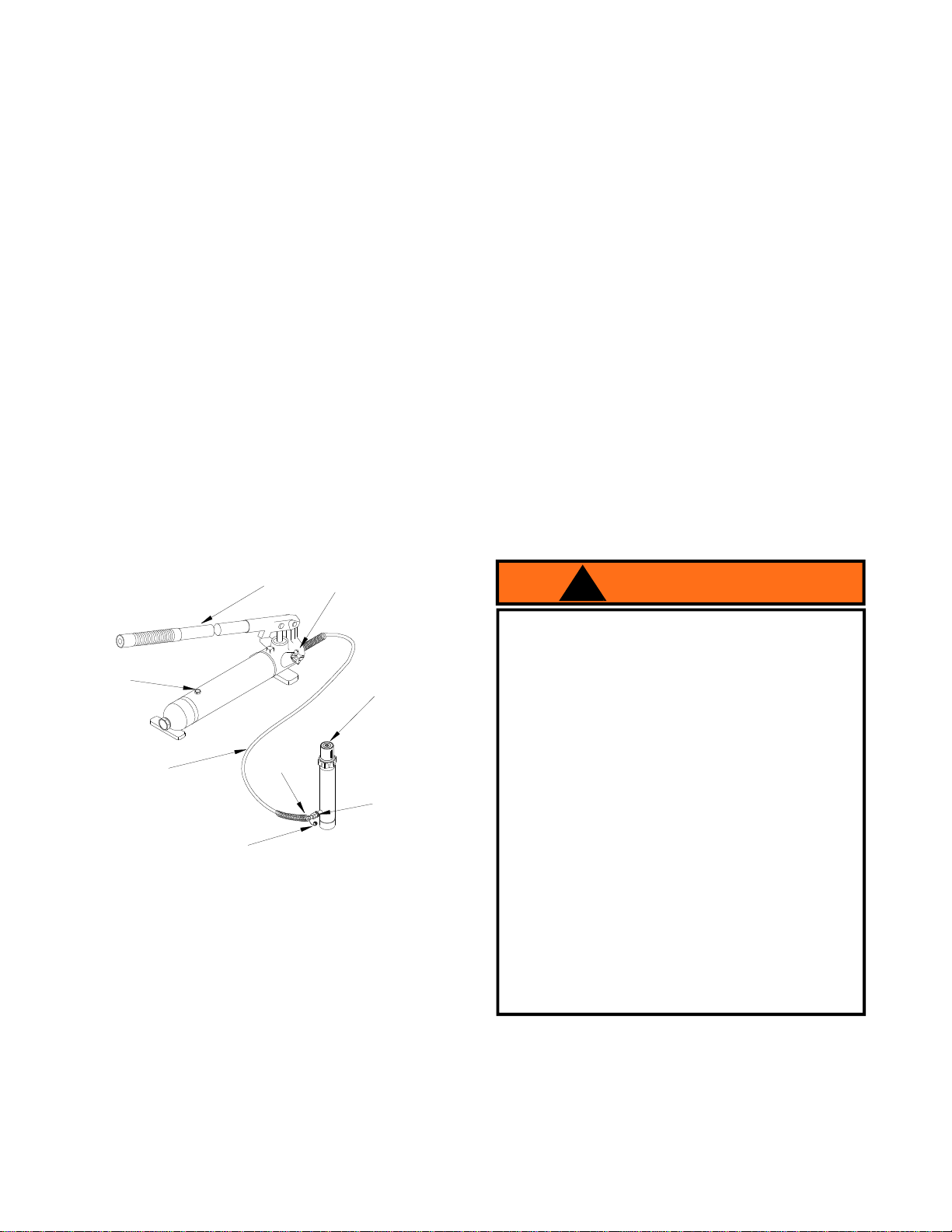
Figure 1- KTI-63705 and KTI-63711 Nomenclature
Dust Cover
Oil Filler
Screw
Handle Release Valve
Ram Plunger
Hose Hose
Coupler
Ram Coupler
KTI-63705-M0

Figure 2 - Horizontal and Vertical Position
OPERATION
Note: Inspect before each use for evidence of fluid
leaks, damaged hydraulic fittings, bent or broken
attachments and missing parts.
1. Locate and close release valve by turning it
clockwise until firmly closed. (Do not over tighten)
2. Operate by pumping handle. This will send fluid
from the pump reservoir into the high pressure hose
assembly and into the ram assembly.
3.Continue pumping until ram reaches desired height.
Note: Pump may be used in horizontal and vertical
position as illustrated (See figure 2).
To Release Pressure on work piece:
Slowly, carefully turn the release valve
counterclockwise until ram retracts to desired
position. Never turn release valve more than
1/2 full turn. The ram return system is spring
loaded.
KTI-63705-M04
MAINTENANCE
Important: Use only a good grade hydraulic jack oil.
Werecommend Mobil DTE13M or equivalent.
Reinstall oil filler screw.Avoid mixing different types of
fluid andNever use brake fluid, turbine oil,
transmissionfluid, motor oil or glycerin. Improper fluid
cancause premature failure of the ram and the
potentialfor sudden and immediate loss of load.
Adding oil
1. With ram fully lowered, set pump unit in its normal,
levelposition. Locate and remove oil filler screw.
(foundcentrallyonthepumpreservoir)
2. Fill until oil is within 3/8" of the oil filler screw hole
opening, reinstall oil filler screw.
Changing oil
Forbest performance and increased system life,
replace the complete fluid supply at least once per
year.
1. With ram fully lowered, remove the oil filler screw
fromthepump reservoirasabove.
2. Lay the pump on its side and drain the fluid into a
suitablecontainer.
Note: Dispose of hydraulic fluid in accordance with
local regulations.
3. Set pump in its level upright position.
4. Fill with good quality oil to within 3/8" of the oil filler
screw hole opening. Reinstall oil filler screw.
Lubrication
A coating of light lubricating oil to pivot points and
hinges will help to prevent rust and assure that
pumpassemblies move freely.
Cleaning
Periodically check the pump piston and ram for signs
of rust or corrosion. Clean as needed and wipe with an
oily cloth.
Note: Neveruse sandpaper orabrasive material on
thesesurfaces !
Storage
When not in use, store with the pump piston and ram
fullyretracted.

5
ONE YEAR LIMITED WARRANTY
For a period of one (1) year from date of purchase, KTI, will repair or replace, at its option, without charge,
any of its products which fails due to a defect in material or workmanship, or which fails to conform to any implied
warranty not excluded hereby.
Performance of any obligation under this warranty may be obtained by returning the warranted product,
freight prepaid, to K-Tool International 31111 Wixom Rd. Wixom, MI 48393, phone (248)669-5000.
Except where such limitations and exclusions are specifically prohibited by applicable law. (1) the
CONSUMER'SSOLEAND EXCLUSIVEREMEDY SHALL BE THEREPAIR OR REPLACEMENT OFDEFECTIVE
PRODUCTS AS DESCRIBED ABOVE,and (2) KTISHALL NOTBE LIABLE FOR ANY CONSEQUENTIALOR
INCIDENTAL DAMAGE OR LOSS WHATSOEVER, and (3) THE DURATIONOFANYANDALLEXPRESSEDAND
IMPLIEDWARRANTIES,INCLUDING WITHOUTLIMITATION,ANYWARRANTIES OF MERCHANTABILITYAND
FITNESS FORA PARTICULAR PURPOSE, IS LIMITED TOA PERIOD OF ONE (1) YEAR FROM DATE OF
PURCHASE.
Some states do not allow limitations on how long an implied warranty lasts, so the above limitation may not
apply to you. Some states do not allow the exclusion or limitation of incidental or consequential damages, so the
above limitation or exclusion may not apply to you. This warranty gives you specific legal rights, and you may also
have other rights which vary from state to state.
TROUBLESHOOTING
Symptom Possible Causes Corrective Action
Ram will not lift load
Ram *bleeds off after lift
Will not lift to full extension
•Releasevalvenottightlyclosed
•Overloadcondition
•Fluidlevellow
•Fluidlevellow
•Airtrappedinsystem
•Releasevalvenottightlyclosed
•Hydraulicunit malfunction
•Ensurereleasevalvetightlyclosed
•Remedyoverload condition
•Ensurereleasevalvetightlyclosed
•Replace Ram and / or Pump
•Ensureproperfluidlevel
•Withramfullyretracted,removeoilfiller
screw to let pressurized air escape,
then reinstall oil filler screw
Poor performance
Ram will not lower after unloading •Reservoiroverfilled
•Linkagesbinding •Drain fluidto proper level
•Cleanandlubricatemovingparts
* "Bleedingoff"meansthatjack begins to slowly lower rather than keep load at height.
KTI-63705-M0

Figure 4 - Replacement Parts Illustration for Model No. KTI-63711
KTI-63705-M07
ModelKTI-63711
RefNo Part# Description Quantity
1F100-41100-000 ExtensionTube (27") 1
2F100-41200-000 ExtensionTube (18") 1
3F100-41300-000 ExtensionTube (10") 1
4F100-41400-000 ExtensionTube(4") 1
5F100-41500-000 MaleConnector 1
6F100-40002-000 WedgeHead (offset) 1
7F100-40004-000 SerratedSaddle 1
8F100-40001-000 Flat Base 1
9F100-40006-000 PlungerToe (offset) 1
10 F100-40005-000 RamToe (offset) 1
11 F100-42000-000 RubberHead 1
12 F100-40003-000 CombinationHead (90o)1
13 F040-42000-000 HydraulicSpreader (1000 lb. capacity) 1
14 F040-20012-000 DustCover - Hose 1
15 F040-30007-000 DustCover -Ram 1
16 F040-22201-000 HoseCoupler, Male 1
17 F040-90009-K02 Ram CouplerAssy., Female 1
18 F100-30000-000 RamAssembly 1
19 F040-21000-000 ReleaseValve Knob 1
20 F100-90009-K01 PumpHandle 1
21 F040-22000-000 HoseAssembly 1
22 F040-90009-K01 Oil Filler Screw 1
23 F100-20000-000 Pump Assembly 1
24 F100-00001-000 BlowMoldedCase 1
-F1000S-85 Repair Kit -
-KTI-63711-L0 Label ( not shown) 1
-KTI-63705-M0 Manual 1
Other manuals for PRO Series
1
This manual suits for next models
2
Table of contents
Other K-Tool Power Tools manuals