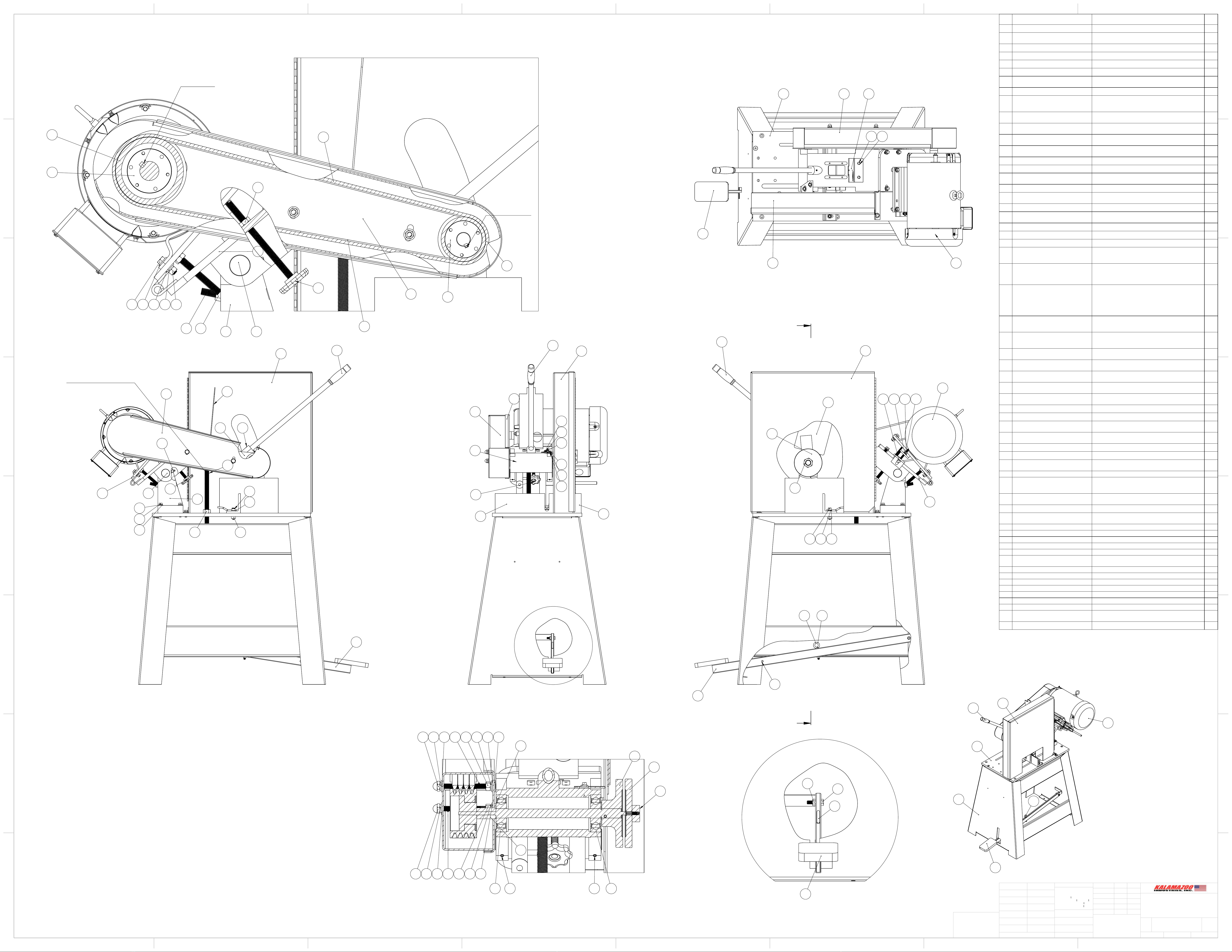
Kalamazoo K16-18 User manual

K16-18 16” TO 18” CHOP SAW
MANUAL
KALAMAZOO
INDUSTRIES, INC.
KALAMAZOO, MI.
PH: (269) 382-2050 www.kalamazooind.com
KI
MADE IN USA

WARNING!
TO REDUCE THE RICK OF FIRE OR SHOCK HAZARD, DO NOT EXPOSE THIS
EQUIPMENT TO RAIN, ANY LIQUID OR MOISTURE.
INSPECTION
If these goods are damaged in transit, the DELIVERING TRANSPORTATION COMPANY is required by law to make notation of damages on
the freight bill. If in your opinion, there may be concealed damage, they are required to make an inspection after goods are unpacked. Transportation
rates are made in proportion to damage. Therefore, the carrier and NOT the shipper should be charged with any loss or damage. Any claim should
be led with the delivering Transportation Company. PLEASE DO NOT RETURN GOODS TO US WITHOUT OUR RGA NUMBER AND
SHIPPING INSTRUCTIONS.
Electrical: CAUTION: Voltage changes require wiring changes at drive motor. WARRANTY DOES NOT COVER unauthorized wiring
changes/failures. Consult an electrician an electrician if your not familiar with electrics.
K16-18 SETUP
• BEFORE STARTING OR CONNECTING ELECTRICAL VERIFY THE PHASE AND VOLTAGE OF THE UNIT.
• BE SURE MACHINE IS BALANCED CORRECTLY SO IT WILL TIP OVER.
• TO GUARD AGAINST CONCEALED DAMAGE, STAND CLEAR AND OBSERVE UNIT FOR THE FIRST FEW MINUTES OF
OPERATION. GUARDS MUST NEVER BE REMOVED.
• BEFORE INSTALLING THE ABRASIVE WHEEL CONFIRM THAT THE CUTOFF WHEEL IS DESIGNED TO RUN AT 2500 SFPM
(MOS). YOU CAN FIND THIS INFORMATION DIRECTLY ON THE THE SIDE OF YOUR CUTOFF WHEEL. IT
ABRASIVE SAW SAFETY
• NEVER REMOVE SAFETY GUARDS FROM MACHINE. DISCONNECT MACHINE FROM POWER SOURCE BEFORE MAKING
ANY MACHINE ADJUSTMENTS.
• DO NOT USE AROUND FLAMMABLE MATERIALS OR LIQUIDS.
• MACHINES SHOULD BE OPERATED IN VENTILATED AREAS.
• ALWAYS WEAR SAFETY GLASSES OR A FULL FACE SHIELD FOR PROTECTION.
• DO NOT USE TOOTHED BLADE WITH THIS SAW AND DO NOT ATTEMPT TO USE STEEL BLADES ON THIS SAW.
• KEEP HANDS CLEAR OF THE CUTTING AREA.
• DO NOT WEAR GLOVES OR LOOSE FITTING CLOTHES WHEN OPERATING THIS MACHINE.
• ALWAYS KEEP HAIR TIED BACK OR COVERED.
• ALWAYS KEEP FLANGES CLEAN AND TIGHT AGAINST CUTTING WHEEL.
• MANUALLY TIGHTEN AND LOOSE SPINDLE NUT.
• DO NOT USE IMPACTED GUN TO LOOSEN OR TIGHTEN SPINDLE NUT.
• ALWAYS KEEP WHEEL GUARD IN THE DOWN POSITION.
• BE SURE WORK PIECE IS CLAMPED SECURELY IN VISE BEFORE CUTTING.
WARNING!!!!
IMPROPER USE MAY CAUSE BREAKAGE AND SERIOUS INJURY.
DO
1. DO always handle and store wheels in the vertical position.
2. DO visually inspect all wheels before mounting for possible
damage.
3. DO check machine speed against the established maximum safe
operating speed marked on the wheel.
4. DO check mounting anges for equal and correct diameter.
5. DO use mounting blotters when supplied with wheel.s
6. DO always use a safety guard covering a least one-half of the
abrasive wheel.
7. DO allow newly mounted wheels to run at operating speed, with
guard in place, for at least one minute before cutting.
8. DO always wear safety glasses or some type of eye protection
when cutting.
9. DO tie back hair.
DON'T
1. DON'T use a cracked wheel or one that has been dropped or has
become damaged.
2. DON'T force a wheel onto the machine or alter the size of the
mounting hole if wheel won't r the machine.
3. DON'T ever exceed maximum operating speed established for
the wheel.
4. DON'T use mounting anges on which the bearing surfaces are
not clean, at and free of burrs.
5. DON'T tighten the spindle nut excessively.
6. DON'T start the machine until the wheel guard is in place.
7. DON'T jam work into wheel.
8. DON'T force cutting so that motor slows noticeable or work gets
hot.
9. DON'T wear gloves and or have loose clothing when operating
machine.
10. DON'T use tooth blade on saw.

BASIC K16-18 AND K20SSF OPERATION
1. Be sure of the correct electrical power (phase and voltage) for the motor. The motor has a wiring
diagram with specications on the outer motor case. Verify electrical power before operating.
Connect incoming AC power to L1, L2, and L3 on the contactor. CAUTION: IF NOT
FAMILIAR WITH ELECTRICAL, CONSULT AN ELECTRICIAN!!! FOLLOW ALL
SAFETY PROCEDURES. SEE THE ABRASIVE SAFETY SHEET.
2. Clamp the part securely. Wrap the chain around the piece over the back fence as tight as possible
(with foot pad to lock pad). Slip the chain link into the clevis; step down and to the right on the foot
pad to close the foot pad and tighten the chain around the part. The part that you need to cut can't
move when clamped. Re-adjust the chain if necessary and re-clamp. NOTE: THE PART
CENTER LINE SHOULD BE AHEAD OF THE WHEEL CENTER LINE. Use any
available piece to lay against the back fence rst, then the part you want to cut. (No need to cut
through spacer/shim).
3. Select the correct abrasive wheel for your job. Abrasive wheels vary in hardness and grain, etc.
incorrect wheels will result in nasty cuts. Good cuts are bright, not blue, and or discolored black.
Please call an abrasive wheel manufacturer to select the correct wheel for your job.
4. As the abrasive wheel wears down, the down stop will need to be adjusted to allow the abrasive
wheel to cut thru your part. Re-adjust the down stop when you put a new abrasive wheel on your
machine. Be sure that you check to make sure that the abrasive wheel does not cut into the abrasive
saw top
5. Use forceful, steady downward pressure when cutting your part. A good shower of sparks will
result. Keep ammable material clear of your work and spark area.
6. Keep drive belts (4 V-belts) tight. 1/2" of slack when squeezed together. Loose drive belts result in
loo of power and binding of the abrasive wheel. Carefully use a prybar to pry the motor mount
back to tighten the v-belts. Re-tighten the threaded knob against the motor plate to x belt tension.
7. Be sure to wear adequate safety protection. Safety glasses, face shield, etc. NOTE: DO NOT
OPERATE IN FLAMMABLE AREAS. DO NOT USE STEEL-TOOTHED BLADES.

X
Y
inch

D
FRONT VIEW
40
46
18
38 37
33
36
10
48
49
50
48
49
50
1
51
53
24
46
40
2
LEFT SIDE VIEW
46 40
18
9
7
8
4
5
X 4 PLACES
33
16
10 41
51
44
X 2 PLACES
STOP HEIGHT IS ADJUSTABLE
54
55
59
60
4
39
X 2 PLACES
A
A
RIGHT SIDE VIEW
24
40
46
35 5 4
X 2 PLACES
16
20 21 22 23
45
13
14
51
53 42
43
LOCATION
LOCATION
25
26
27
28
17 4 4 5 6
X 4 PLACES
97
30
36
30
X 4 BELTS
16
19
18
1/4SQ X 2 KEY
1/4 SQ X 1-1/4 KEY
57 58
DETAIL D
SCALE 2 : 5
51
53
52
23
SECTION A-A
SCALE 1 : 2
INTERNAL SPINDLE VIEW
34 5 4 32 6 5 4 4
56
11 15 15 11
12
13
14
34 5 4 31 6 5 4
29
332
51
24
48 49
59
X 2 PLACES
46
TOP VIEW
ITEM
NO.
PART NUMBER
DESCRIPTION
QTY.
1
716-023
STAND ASSEMBLY FOR K16-18
1
2
050-018A
BASE, PLATE K16-18 (NEW STYLE AFTER
08/20/2014)
1
3
FSCA037020
3/8-16 X 1-1/4 FSHCS
4
4
UFWZ037
3/8 USS F/W Z
34
5
SLWZ037
3/8 SPLIT L/W Z
28
6
FHN5037
3/8-16 FHN GR5 Z
12
7
831-021
TRUNNION FOR KM16-18, K16-18, K20SSF
(NEW STYLE)
1
8
HHC5037036
3/8-16 X 2-1/4 HHCS GR 5 Z
4
9
700-003
NEW STYLE TRUNNION PIN FOR K16-18, KM
STYLE TRUNNION, K20SSF
1
10
002-005
SAW ARM FOR K16-18, KM16-18, AND K20SSF
SAW
1
11
044-004
K20 SPINDLE BEARING
2
12
701-010
SPINDLE W TIGHT FLANGE FOR K16-18,
K20SSF, K20E SAWS
1
13
292-011
LOOSE FLANGE FOR K16-20, KM16-18, KM20-
22 1
14
537-027
SPINDLE NUT FOR K16-20
1
15
SSKA031006
5/16-18 X 3/8 SOC SET KNURL PT.
2
16
486-010
MOTOR MOUNT PLATE FOR K16-20 ASSEMBLY
1
17
HHC5037020
3/8-16 X 1-1/4 HHCS GR5 Z
8
18
696-029
MOTOR PLATE TENSION SCREW FOR K16-K20
SAWS
1
19
FJNZ050
1/2-13 F H JAM NUT Z
1
20
CRBZ031040
5/16-18 X 2-1/2 CARRIAGE BOLT Z
1
21
UFWZ031
5/16 USS F/W Z
1
22
SLWZ031 5/16 SPLIT L/W Z
1
23
FHN5031
5/16-18 FHN GR5 ZINC
2
24
486-019
10HP MOTOR FOR K16-18, KM16-18, BG14
1
25
560-046
MOTOR PULLEY SHEAVE FOR K16-18, KM16-
18, K20SSF-15, KM20-22/15, KM20-22W/15
(K20SSF 7 1/2 HP), SPINDLE PULLEY SHEAVE
FOR K20SW-15HP & 20HP
1
26
049-003
MOTOR PULLEY BUSHING FOR FOR K16-18,
KM16-18, K20SSF-15, K20RS-15, K20SW-15,
KM20-22-15HP, KM20-22W-15
FOR K16-18, KM16-18, K20SSF-15, K20RS-15,
K20SW-15,
KM20-22-15HP, KM20-22W-15
1
27
560-047
SPINDLE PULLEY SHEAVE FOR K16-18, KM16-
18, K20SSF-15, K20RS, KM20-22/15, MOTOR
PULLEY SHEAVE FOR K20SW-20HP
1
28
049-004
SPINDLE PULLEY BUSHING FOR K16-18, K20SSF-
15HP, K20RS-15
KM16-18, KM20-22-15HP
1
29
RND-3/4CFC1018X7/8
7/8 INCHES OF RND-3/4 CF C1018
1
30
051-005
V-BELT FOR K16-18, K20SSF, K20E,
K20RS, K20SW
4
31
RND-3/8-16THRDRODX6.25
6-1/4 INCHES OF RND-3/8-16 THREADED ROD
1
32
RND-3/8-16THRDRODX5.375
5-3/8 INCHES OF RND- 3/8-16 THREADED ROD
1
33
342-039
OUTER GUARD, BELT FOR K16-18 AND K20SSF
SAWS
1
34
CPNZ037
3/8-16 CAP NUT NICKEL
2
35
SHCA037020
3/8-16 X 1-1/4 SHCS
2
36
342-039A
GUARD, INNER BELT FOR K16-18, KM16-18,
K20SSF SAWS
1
37
293-003
FENCE, RIGHT FOR K16-18, K20SSF
1
38
293-002
FENCE, LEFT FOR K16-18, K20SSF
1
39
SHCA037024
3/8-16 X 1-1/2 SHCS
2
40
381-009
HANDLE WITH GRIP FOR K16-20 ABRASIVE
SAW
1
41
SSKA025006
1/4-20 X 3/8 SOC SET KNURL PT.
1
42
697-021
SPRING FOR HOOK CHAIN ASSY FOR K16-18
AND K20SSF CHAIN VISE
1
43
697-022
SPRING, FOOT PEDAL FOR K16-18 AND
K20SSF SAWS
1
44
ZERK012000
1/8-27 X 11/16 STRT LUBE FITTING
2
45
342-030
INNER WHEEL GUARD FOR K16-18, K20SSF
SAWS
1
46
342-014
WHEEL GUARD FOR K16-18 SAW
1
47
HHC5037016
3/8-16 X 1 HHCS GR5 Z
4
48
HHC5025008
1/4-20 X 1/2 HHCS GR5 Z
4
49
SLWZ025
1/4 SPLIT L/W Z
4
50
UFWZ025
1/4 USS F/W Z
2
51
041-007
Default
1
52
HHC5031020
5/16-18 X 1-1/4 HHCS GR 5 Z
1
53
TEBZ031032
5/16X2 TURNED EYE BOLT Z
1
54
709-003
STOP, DOWN FOR K16-18 AND K20SSF SAWS
1
55
FHN5075
3/4-10 FHN GR5 Z
1
56
049-116
SPACER BUSHING FOR K20 SERIES SPINDLE
1
57
RND-1/2-13THRDRODX2
2 INCHES OF RND-1/2-13 THREADED ROD
1
58
FHN5050
1/2-13 FHN GR5 Z
1
59
041-092
SWITCH BRACKET FOR MAG SWITCH ON K20
ARM
1
60
537-007
LONG FENCE NUT FOR K16-20 SAWS
1
A A
B B
C C
D D
E E
F F
G G
H H
8
8
7
7
6
6
5
5
4
4
3
3
2
2
1
1
K16-18 CUT-OFF
SAW
DO NOT SCALE DRAWING
K16-18
SHEET 1 OF 1
UNLESS OTHERWISE SPECIFIED:
SCALE: 1:5
WEIGHT:
REV
DWG. NO.
E
SIZE
TITLE:
NAME
DATE
COMMENTS:
Q.A.
MFG APPR.
ENG APPR.
CHECKED
DRAWN
FINISH
MATERIAL
INTERPRET GEOMETRIC
TOLERANCING PER:
DIMENSIONS ARE IN INCHES
TOLERANCES:
FRACTIONAL
ANGULAR: MACH
BEND
TWO PLACE DECIMAL
THREE PLACE DECIMAL
APPLICATION
USED ON
NEXT ASSY
PROPRIETARYAND CONFIDENTIAL
THE INFORMATION CONTAINED IN THIS
DRAWING IS THE SOLE PROPERTY OF
<INSERT COMPANY NAME HERE>. ANY
REPRODUCTION IN PART OR AS A WHOLE
WITHOUT THE WRITTEN PERMISSION OF
<INSERT COMPANY NAME HERE> IS
PROHIBITED.
This manual suits for next models
1
Table of contents
Other Kalamazoo Saw manuals

Kalamazoo
Kalamazoo K10B User manual

Kalamazoo
Kalamazoo KM14 User manual

Kalamazoo
Kalamazoo K12-14V User manual

Kalamazoo
Kalamazoo K10B User manual

Kalamazoo
Kalamazoo AH9AW KALAMATIC User manual

Kalamazoo
Kalamazoo K12-14B User manual

Kalamazoo
Kalamazoo KM14 User manual

Kalamazoo
Kalamazoo K10SW User manual

Kalamazoo
Kalamazoo K20SW-15 User manual

Kalamazoo
Kalamazoo K26S User manual