Kalkomat Comboboxer Manual

COMBOBOXER
Punch-Force measuring machine
Technical Information

2
Index:
1. Introduction .............................................................................3
2. Usage/Purpose.........................................................................3
3. Technical Data........................................................................4
4. Assembly/ Construction description.........................................4
5. Transport .................................................................................6
6. Installation...............................................................................6
7. Usage instructions....................................................................7
8. Maintenance check list, problem prevention and day-to-day
conservation...........................................................................9
9. Quick check for potential errors.............................................13
10. Machine setup......................................................................17
11. Spare parts and equipment ...................................................44
12. Standard replacement parts ..................................................44
13. Required tools and equipment for servicing the boxing game44
14. Step by step setup and maintenance instructions...................45

3
1. Introduction
Main purpose of this Technical Information is to:
-familiarize user with machine construction,
-provide proper setup parameters, installation and power line
hookup,
-familiarize user with proper and safe usage procedures,
exploitation and conservation.
WARNING! USER MUST FOLLOW
ALL GUIDELINES INCLUDED IN THIS
DOCUMENT FOR SAFE AND LONG
LASTING MACHINE USAGE.
2. Usage/Purpose
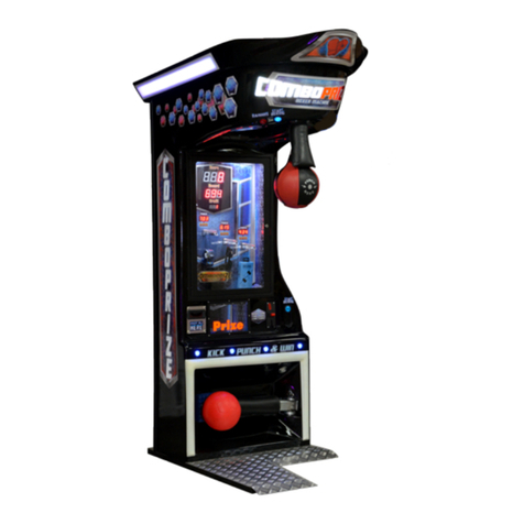
Comboboxer is a punch-force and kick-force measuring machine.
The machine is designed to allow players to choose between two game
types: boxing and kicking.
This machine allows to measure punch-force (boxing power
game), kick-force (kicker power game) and play a power tournament game
between up to 6 players, either as a boxing game or kicking game.
Comboboxers can be placed in night clubs, gyms, bars etc., generating
tons of positive fun and allowing players to check/measure their boxing
skills or their kicking skills. Complete and detailed usage instructions are

4
under paragraph 7 of this document and on the sticker placed on each
machine.
3. Technical Data
Model
COMBOBOXER
Depth [in]
51
Width [in]
34
Height [in]
85
Overall Mass [Lb]
351
Power consumption [Wh]
200
4. Assembly/ Construction description
Punch-force and kick-force measuring machine Comboboxer is built
out of three main components:
-base,
-middle assembly,
-top assembly.
The key component is a mother board (electronic board) placed
inside Boxer’s body (block schematics drawing #1) to which
mechanical elements and user interface components are connected.
Electric/ electronic part contains following:

5
-power supply (drawing #4 and drawing #5) –consists of
transformer, fuses and broadcasters that control alarm sirens
& electromagnet –transforms voltage from 110 V to 12 V
(connected to main board J6),
-measuring mechanism –consists of sending and receiving
diodes that measure blade fly speed through assembly,
-verbal information mechanism –built using potentiometer
and speaker, used to send voice messages,
-punching bag lowering mechanism –consists of button
START with backlight and electromagnets –actual
lowering mechanism,
-kicking ball lowering mechanism –consists of button
START with backlight and electromagnets –actual
lowering mechanism,
-visual information assembly –assembled out of diodes used
for visual representation of punch force measurement,
warning siren (informs player of breaking top record) also
displays on electronic panel (shows measurement result,
credit amount, top day record),
-coin acceptor –used to deposit coins (can be reprogrammed
to tokens or other currencies),
-bill acceptor –used to deposit bills (optional),
-mother board.

6
5. Transport
Machine should be transported in vertical position. Machines are shipped
on a wooden 41” x 53” palette, and sides are covered with special thick
(~3/8”) multi-layer cardboard 93” tall (from the bottom of the pallet). The
total weight of the box is approx. 491 lbs.
After machine is taken out of the box, it should be transported in
horizontal position with the help of two wheels. Machine can, in special
cases (exp. if it does not fit in doorway), be taken apart and then
reassembled. This procedure should be done by a specialist or someone
familiar with all technical information.
6. Installation
Machine, after being taken out of the box, should be placed in vertical
position and the base should be leveled. To level the machine correct tools
should be used (exp. laser level or typical manual construction heavy duty
level). Turning several screws under the base allows for level adjustment.
After plugging the machine to grounded power outlet it should be ready to
use. Please note, machine placed outdoor MUST be connected to
grounded GFCI type power outlet.
Make sure that there is enough clearance on the sides and in front of the
machine, so the player will not hit any objects or person after punching the
bag. Recommended safety radial distance if 5 feet from the point where
the bag drops to the lower position. Make sure that machine is not
accessible from it’s back to anyone while played. The installer of the
machine is responsible for defining the safe clearance.

7
7. Usage instructions
a) It is recommended to use warm up punches before the maximum
strength punch.
b) For the first time user, please practice with several easy test
punches before your maximum punch.
c) Read the user instructions placed on the machine,
d) Select type of game (default setting is power mode for both, the
boxing and the kicking game) by pressing SELECT GAME button
located on the main body of the game. Player can choose between
following types of game: power, tournament for 2 players, tournament
for 3 players, tournament for 4 players, tournament for 5 players,
tournament for 6 players. Pressing the SELECT GAME button will
2 Players
3
Players
4
Players
Power
5
Players
6
Players
SELECT
GAME

8
cycle through the available modes as illustrated in the diagram above.
e) Before pressing the START button player must stand in front of the
Comboboxer.
f) Start game (Boxer or Kicker/Soccer) by either pushing ‘Start boxing’
(for Boxer) or ‘Start Kicking’ (for Kicker/Soccer) button.
g) After pressing the START button player has to wait in front of the
machine for the punching bag to be released from the upper position
(for Boxer) or for the kicking ball to be released from the blocked
position (for Soccer).
h) (For Boxer) After the punching bag is released, player should make a
fist so the thumb would be on the outside of the pointing and the
middle finger.
i) The punch/ kick must be placed in the center of the punching bag/
kicking ball.
j) After the punch/kick, a score would be displayed on the front panel.
k) Follow the same instructions before the next game.

9
8. Maintenance check list, problem prevention and day-to-day
conservation
Every two weeks (recommended):
-check the air pressure of the bag and the ball - it should be NO
MORE than 2psi, no less than 1.5psi,
-check if the bag is not rotating about its own axis. If it is, see point
D in this section,
-check the position of the arm protectors (see point H in this
section),
-check all of the connections on the main board,
-check the level/ balance of the machine (if needed, use adjusting
legs under the machine to bring the machine to level),
-check if the usage instructions and disclaimers are readable.
Every month:
-check mounting cover screws/nuts,
-check the lubrication of the mechanism (for instructions see point
C in this section),
-check the display lights,
-clean the bill acceptor (if installed).
A) Coin acceptor maintenance
Coin acceptor should be cleaned periodically (every 2000 - 3000 credits).
Best way to clean it is by using simple cloth slightly soaked in distilled
alcohol. Focus should be placed on cleaning the area where coins slide
through (make sure sliding part is in open position).

10
B) Sound volume regulation
R362 potentiometer (see drawing #1) used to control volume is placed on
the right side of the electronic board. The volume adjustment can be done
by rotating the potentiometer to the left or right.
C) Maintenance of mechanism and regulating spring
Periodically (once a month or more often, or if the lowering speed of
punching bag or kicking ball is fairly low) all moving elements should be
rubbed/ sprayed with WD-40 or grease.
If punching bag or kicking ball lowers slowly or too fast one should check
if spring is properly stretched. Spring can be adjusted with screw that is in
the front left side after taking the masking net.
In case of forced lowering mechanism replacement one should unscrew
plastic casing, and then take off masking board (black from the bottom)
and remember about the retro cop light.
D) Manual punching bag reposition
In case the punching bag is vibrating too much (or if it is rotating around
its own axis), the top nut located on the punching bag screw should be
tightened (loosen the lower nut first) until the bag is not rotating any
more.
E) Replacement of inner punch bag bladder
To replace inner bladder of the punch bag or kicking ball one should untie

11
rope, take out old insert and replace it with a new rubber bladder. A
special attention must be paid to the location of the bladder valve. The
valve must be placed in the opening of the leather cover.
F) Bulb replacement, GAME button
In case of bulb failure in the GAME button one should take out micro-
switch from the casing (by slight turn and then pull) and then proceed
with bulb replacement [bulb spec: 12 Volt & 3 Watt].
G) Fuse replacement
Machine is equipped with two long term fuses. One at power supply
assembly and the second one on the main electronic board [specs: 250V &
4 A]. In case of short circuit situation and/or insufficient power supplied to
the electronic main board one should first check the fuses and if they are
burned, then proceed with replacement. Make sure fuses used to replace
old one have the same specifications.
H) Position of the Arm protector
DO NOT PLAY THE GAME WITHOUT PROPERLY
PLACED ARM PROTECTOR.
The position of the arm protector should be like on the picture below:

12
The following two pictures illustrate an improper setup of the punching
bag. NEVER leave the machine in this state. The picture on the left shows
the arm protector placed too high. The second picture shows the missing
arm protector. Both of these cases may result in serious injury to the user.

13
9. Quick check for potential errors
Main board not functioning:
1Check all fuses (5A).
2Check the connection between main power supply and the main
board.
3Make sure that the main processor and other connectors are well
seated.
4All displays can be checked by turning the switch #1 to “ON”
position than turning machine off and back on.
Coin Acceptor is not functioning:
1Check if it is not clogged up.
2Check for dust and dirt.
3Check strip connecting the main board with the acceptor.
Mechanism is not functioning:
1Using just power supply check if it is possible to lower
punching bag (using manual switch, black button above the 12V
connector - see drawing #4 or drawing #5).
2Check for burned fuse 30A.
3Check button functionality and if they have proper connection.
4Check for unhooked cable from power supply spools.
5Check strip connecting the main board with the power supply.

14
Sensor is not functioning:
1Check sensors in service mode (first press “Start Boxing” [when
checking Boxer] or press “Start Kicking” [when checking
Kicker/Soccer] and use switch #1 on the main board (S1) and
manipulate button SW1 go to mode P07), if punching bag
(while checking Boxer) or kicker arm (while checking
Kicker/Soccer) is moving UP/DOWN and on the main board
(depending on bag/arm position) HI –LO shows this would
indicate that sensor is working.
2Check if sensor cable is firmly connected to the main board.
3Check all wires to/from the sensor.
Halogen lights are not functioning:
1Check power supply cable connection.
2Check power supply wire integrity.
3Check connector plug for loose bulb.
4Check if halogen is not burned by swapping it with a new one
(12V 20W).
Button START or GAME is not functioning:
1Check for main board cable connection.
2Check switch/button cable connection.
Computer power supply is not functioning:
1Check if power supply cable is plugged in securely.

15
Power supply is refusing to work:
1Check if “car” fuse in power supply is not burned (30A).
2Check if transformer cable is correctly hooked up to power
supply socket.
Machine is not starting:
1Check power cable & fuse 5A.
2Check if ON/OFF switch (filter) is not damaged.
Counter is showing Err:
1Check if mechanical counter did not come loose (then turn the
machine OFF and ON).
Bill Acceptor is not functioning:
1Check if power supply cable is hooked up to main board (J3).
2Check if cable from bill acceptor is correctly hooked up.
3Check acceptor settings using switches: for switches 1-8 set 7 at
ON, and for switches 1-4 set 3 & 4 at ON.
Sound is not working:
1Check if it is not at low volume or mute (R362).
2Check if cable is correctly connected to the main board.
3Check if cable to speaker is correctly connected.

16
Red diode active on main board:
1Usually caused by circuit being shorted at scale bulb array,
check all cables for potential shortage.

17
10. Machine setup
Main Board Layout (Back Side)
Drawing #1

18
List of connectors:
J1 –connector for coin acceptor
J2 –connector for bill acceptor
J3 –connector for power supply to bill acceptor, ticket
dispenser, capsule dispenser, thermal printer
J4 - connector for ticket dispenser, capsule dispenser, thermal
printer
J5 & J7 –front panel backlight
J6 –connector for main board power supply (12V supplied by
AC power supply)
J8 –connector for power supply
J9 –sensor connector
J10 –connector for buttons GAME and START BOXER
J11 –connector for mechanical counter
J12 –connector for speaker
SW-ADD –connector for START KICKER
S1 –service setting switches
S2 –step potentiometer for setting sensor sensitivity (0 –min,
9 - max)
SW1 & SW2 –help buttons (up/down)
R362 –potentiometer for volume control
IC37 –speech synthesizer
IC34 –main processor socket
LED-A - connector for Kicker power supply
LED-B - connector for Boxer and Kicker sensors
LED-C - connector for siren (optional)
PRINTER - connector for thermal printer
BOXNET/ TOURNAMENT - connector for BoxNet or
BoxTournament for PC
LED-A and LED-B connectors

19
Dip Switch 1-8 (S1)
THE RED (BLACK OR BLUE)SWITCH BOX WITH 8SWITCHES IS
LOCATED ON THE LEFT SIDE OF THE MAIN CIRCUIT BOARD.TO
PROGRAM,SWITCH #1 MUST BE SET TO "ON" POSITION WHEN
MACHINE IS “ON”.
PUSH BUTTONS SW1 ↑AND SW2 ↓ARE LOCATED IN THE LOWER LEFT
PART OF THE MAIN CIRCUIT BOARD.
Switch #1
THIS SWITCH IS USED TO ENTER THE PROGRAM SETTINGS.
PLEASE USE BUTTONS SW1 ↑ OR SW2 ↓ FOR FINDING THE
RIGHT PROGRAM P01-P96. DESCRIPTIONS FOR EACH
PROGRAM ARE LISTED BELOW. DURING PROGRAM
SELECTION YOU WILL SEE P01-P96 ON THE MAIN DISPLAY.
REMEMBER, FOR SOME SETTINGS YOU WILL USE “START
BOXING”, “START KICKING” OR “SELECT GAME” BUTTONS.
Switch #1
SW1 & SW2

20
P01 TEMPORARY COUNTER OF POINTS. 1 POINT = $.25 (25
CENTS).
YOU CAN RESET IT TO 0000 BY PUSHING AND HOLDING
THE "START BOXING" BUTTON FOR 3 SECONDS.
P02 COUNTER OF POINTS. THIS IS LIFE LONG - NOT
ERASEABLE.
P03ELECTRONIC COUNTER OF REVENUE (COUNTS THE
QUOTERS WHILE THE MECHANICAL COUNTER IS
DISCONNECTED).
P04 CREDIT RATIO. HOW MANY QUARTERS ($.25) IS NEEDED
FOR 1 CREDIT.
THE LEFT SIDE OF THE RATIO IS CONTROLLED BY THE
“START BOXING” BUTTON.
Example: 1 credit is worth four quarters ($1), so the P04 will be set to
4 - 1.
1 credit is worth two quarters (50 cents), so the P04 will be
set to 2 - 1.
NOTE: IF THE BILL ACCEPTOR IS SET 4 PULSES FOR A 1$,
SET P09 TO 12 (in case of the older software to 5).
P05 YOU CAN SET ADDITIONAL CREDITS (BONUS CREDITS)
WHEN A SET DOLLAR AMOUNT IS INSERTED. USING THE
“START BOXING” BUTTON YOU CAN ADJUST HOW MANY
QUARTERS RECEIVED AT ONCE WILL GIVE THE BONUS.
USING THE “SELECT GAME” BUTTON YOU WILL THEN
ASSIGN NUMBER OF CREDITS FOR THE RECEIVED
AMOUNT.
Example: you want to set 8 credits (punches) for $5, you should set
P05 to 20-8. NOTE: SEE SETTING P65.
P06 THIS SETTING FUNCTIONS THE SAME AS P05 BUT ALWAYS
FOR BIGGER VALUE OF THE BILL OR COIN THAN P05.
Example: if you want to set 8 credits (punches) for $5, you should set
P05 to 20-8.
if you want to set 18 credits (punches) for $10, you should
set P06 to 40-18. NOTE: SEE SETTING P65.
Table of contents
Other Kalkomat Arcade Game Machine manuals
Popular Arcade Game Machine manuals by other brands

MADEFORARCADE
MADEFORARCADE VIRTUAL PINBALL user manual

numskull
numskull Quarter Arcades PAC-MAN instruction manual

SEGA ENTERPRISES
SEGA ENTERPRISES DIRT DEVILS owner's manual

BMI Gaming
BMI Gaming SHIRTS AND SKINS Operator's manual

Sega
Sega RALLY 3 DELUXE owner's manual

Sega
Sega MISSION: IMPOSSIBLE owner's manual