Diagram B
Diagram C
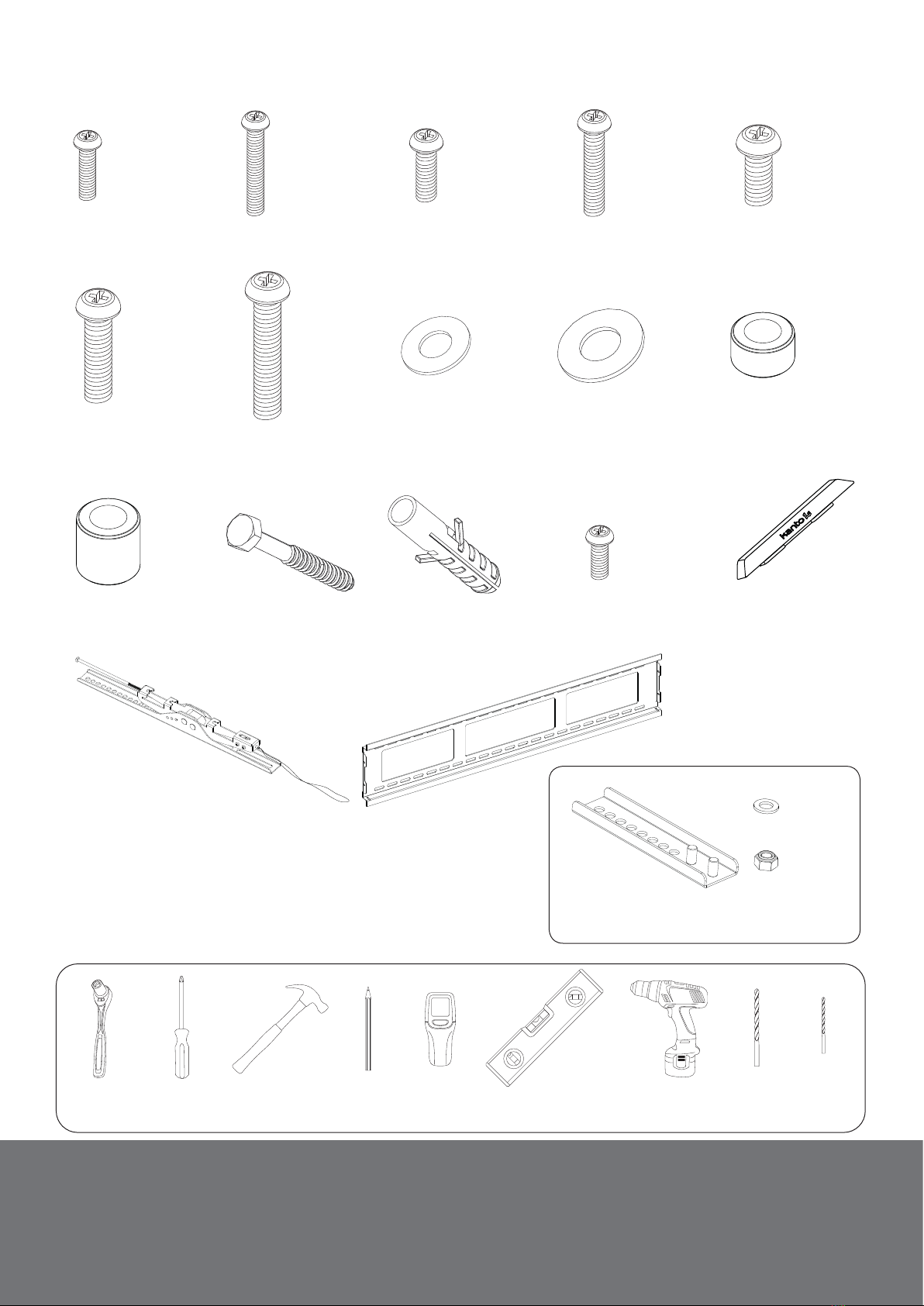
I
L
I
L
M
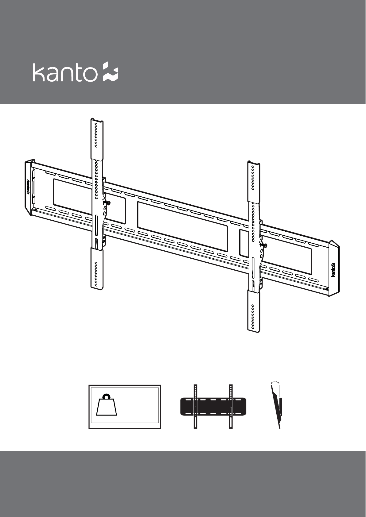
Supporting your digital lifestyle™
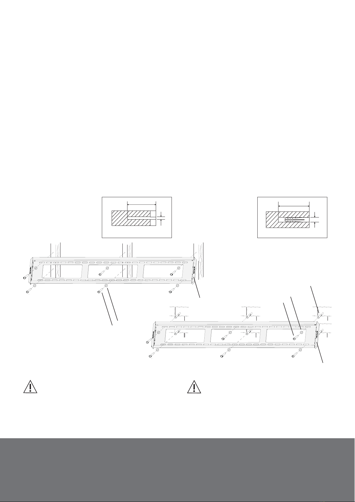
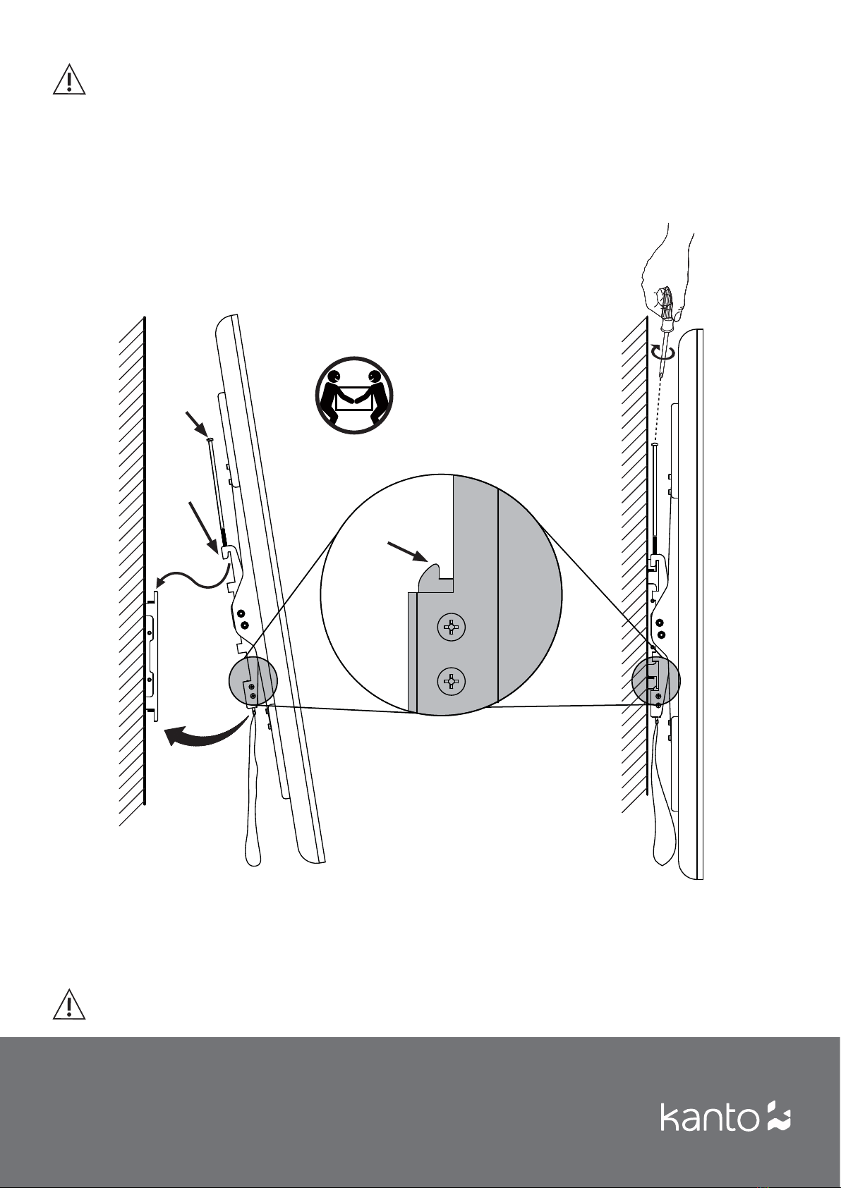
Step 2: Mount Wall Plate
Wood Stud Wall
The Wall Plate can be mounted to three wood studs with
16” centers, or to two wood studs with 24” centers. Use
a stud sensor to locate the studs, clearly marking the
outer edges of the studs. Use a long level to ensure the
hole marks are level at the desired height.
Pre-drill the upper holes in the center of your studs
and attach the Wall Plate to the wall using Lag Bolts (L)
and Lag Bolt Washers (I) (see Diagram B for three stud
installation - we recommend you center the plate if you
have two 24” studs). Do not over-tighten Lag Bolts (L).
Make sure the Wall Plate is flat against the wall surface.
Using the Wall Plate as a template, pre-drill the bottom
holes, and secure using Lag Bolts (L) and Lag Bolt
Washers (I), taking care not to over-tighten.
Brick or Concrete Wall
Using the Wall Plate as a template, mark six holes (four
toward the outer edge of the Wall Plate and two near
the center) at your desired height. Adjust the Wall Plate
position to be clear of mortar joints, keeping in mind
that the mount provides minor horizontal shift along the
length of the Wall Plate. Use a long level to ensure the six
hole marks are level and at the desired height.
Pre-drill six holes, and insert a Concrete Anchor (M) into
each of the holes flush with the concrete wall surface
and not flush with the surface covering, such as drywall.
Attach the Wall Plate using 6 Lag Bolts (L) and Lag Bolt
Washers (I) (see Diagram C). Make sure the Wall Plate
is flat against the wall surface. Do not over-tighten
Lag Bolts (L).
CAUTION
Make sure the supporting surface will support
the load limits outlined in the Caution at bottom
of page two. Tighten Lag Bolts until the Wall Plate is snug
flat against the wall. Do not over tighten Lag Bolts (L).
Each Lag Bolt must be located in the center of a wood
stud.
CAUTION
Make sure the concrete or brick wall is at least
3.5” thick. Make sure the anchor is seated completely
flush with the concrete surface even if there is another
layer of material, such as drywall. If drywall is over 5/8”
thick custom lag bolts must be used. Concrete must be
a minimum of 2000psi in density.
Wood Concrete
3/16”
(5 mm)
3” (75 mm) 3” (75 mm)
7/16”
(11mm)
O
O
Attach the two plastic End Caps (O) to the Wall Plate.
Supporting your digital lifestyle™5