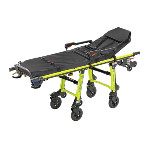
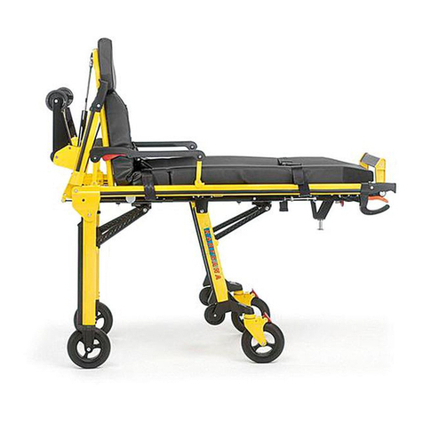
Kartsana BRAVA User manual

OPERATING AND HANDLING
THE BRAVA POWER STRETCHER

OPERATING AND HANDLING
THE BRAVA POWER STRETCHER
CONTENTS
1.- Introduction
Pages
1.1.- Foreword…............................................................................................................................................ 1
1.2.- Warranty and liability............................................................................................................................ 2
1.3.- Warning................................................................................................................................................. 2
2.- Instructions Manual
2.1.- Technical data for the BRAVA stretcher………………………………………………………………………. 3
2.2.- Operating and using the BRAVA stretcher ………...………………………………………………………… 4
2.2.1.- Installing the batteries……........................................................................................................... 4
2.2.2.- Starting and controlling the stretcher…..………………..……………………………………..………. 5
Incidents display panel…………………………..……................................................................ 6
2.2.3.- Adjustable reclining back rest…………………………………………………………………………… 9
2.2.4.- Extendable back rest frame ………………………………………………………………………………9
2.2.5.- adjustable leg rest ..……………………………………………………………………………………… 10
Button for adjusting leg rest inclination................................................................................... 10
Button for adjusting foot rest inclination……………………..…............................................... 11
2.2.6.- Safety handrail ……………………………………………………………………………………………. 11
2.2.6.1.- removable safety handrail .................................................................................................. 12
2.2.7.- drip holder ………………………………………………………………………………………………… 12
2.2.8.- Method for fastening the belts to the patient …………………………………………………………. 14
2.2.8.1.- Back rest belts …………………………………………………………………………………… 14
2.2.8.2.- Abdomen belts……………………………………………………………………………………. 14
2.2.9.- Assembling the belts in the stretcher …………………………………………………………………. 15
Anchoring with a ring……………………………………………..……....................................... 15
Anchoring with a plate ……………………….......................................................................... 15
2.2.10.- Belt position
2.2.10.1.- Side belts……………………………………………………………………………………....... 16
2.2.10.2.- Back rest belts …………………………………………………………………………........ 16
2.2.11.- Back wheel brake lever ……………………………………………………………………………….. 17
2.2.12.- Back wheel release lever ……….…………………………………………………………………….. 17
2.2.13.- Joining the brava stretcher to the bravo rail ………………………………………………………… 18
3.- Faults ………................................................................................................................................................. 21
4.- Disinfection……………………..................................................................................................................... 21
5.- Maintenance…………………........................................................................................................................ 22
6.- BRAVA exploded view ……………………………………………………………………………………………… 23
7.- Accessories ..................……………………………………………………………………………………………… 32
OPERATING AND HANDLING
THE BRAVA POWER STRETCHER
1
1.- INTRODUCTION
1.1.-Foreword
The BRAVA stretcher has been solely designed to rescue and transport patients. The
product complies with the directive 93/43/EWG. It is an electric-hydraulic model that
allows the height to be adjusted according to different needs, with just two buttons.
Manual operation is possible when potential faults in the automated system occur.
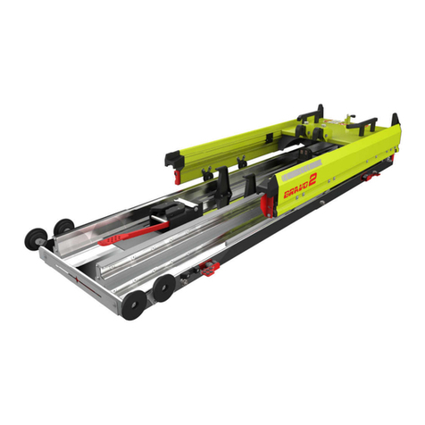
The BRAVA stretcher model must be joined to the ambulance using the KARTSANA BRAVO rail.
This stretcher has been tested according to the regulation UNE-EN 1789.
All information regarding treatment, disinfection and maintenance is indicated, taking
into consideration our current experience and know-how. The drawings are not on a 1:1
scale.
We reserve the right to change the specifications of the stretcher to improve the products.
Maximum duty cycle.
60 seg. - operating
maximum time.
100 seg. - Idle time.
Read the instructions manual Maximum load 300 Kg.
before using.
Medical Product class I. Electrical isolation class II.
- Do not throw away. Send to recycling center.
- Packing should be manage as a reusable refuse.
- Metals should be treated as old metal.
- Plastic product should be treated as recycling material.
- Waste management must be as regulation of the country.
- Ask municipal administration about recycling and refuse.
BRAVA information
sticker

OPERATING AND HANDLING
THE BRAVA POWER STRETCHER
2
1.2.-Responsibility and warranty
The stretcher must be checked at the time of its delivery to the rescue organisation. All
its functions must be explained in great detail. The assistance organisation must take
charge of teaching all its employees how to use it correctly.
The product has a 24-months warranty from the delivery date to the end user (see the
Warranty terms and conditions and the Warranty Certificate which is supplied with the
product).
The warranty does not cover defects resulting from incorrect installation, misuse or
improper use of the stretcher. All repairs must be made by a technical service
authorised by Kartsana or its respective representative.
The manufacturer will not be liable for any anomaly caused to the stretcher as a result of
using products other than those provided by Kartsana.
Other warranty clauses, see the Warranty Terms and Conditions that are supplied with
the product.
1.3.-Attention
Through this sign, information is furnished on important safety measures for
the correct use of the stretcher, in order to prevent accidents.

OPERATING AND HANDLING
THE BRAVA POWER STRETCHER
3
2.- INSTRUCTIONS MANUAL
2.1.-Technical specifications BRAVA stretcher
Make sure that no damage is caused to the areas containing the stretcher
mechanisms, to prevent them from malfunctioning.
Stretcher weight 69 kg
Trolley dimensions: Elevation in mm

OPERATING AND HANDLING
THE BRAVA POWER STRETCHER
4
2.2.-Operating and handling the stretcher
2.2.1.-Installing the battery
The first step when working with Brava is to install the two 24 V. batteries which
power the system. To do this, we open the rear black cover and place the batteries
opposite their housings at the back of the stretcher and push until it locks.
To remove each of the batteries, press the small trigger located on the lower left
hand side and pull carefully. Both batteries work independently of each other. The
system will run down the first battery and then start to work with the second.
Each battery life under normal circumstances (from 80 to 120 kg load) should be
about 20 cycles. When a battery approaches discharge the system will use the
second battery.
Note: The front part of the stretcher corresponds to the head part.
Note: Batteries are delivered with a minimum charge. Prior to operating the bed we
charge the batteries with the charger supplied, until the LED turns green it. After that
we can work normally.
Trigger to
remove battery

OPERATING AND HANDLING
THE BRAVA POWER STRETCHER
5
2.2.2.-Starting and controlling the stretcher.
To avoid potential injury to the patient and companions, do not place
objects in the way of the moveable parts of the stretcher. It is also recommended to
avoid having objects that stick out the ambulance.
The stretcher has a security system to avoid collapse in the case of
system failure.
To start the system we must press the yellow button on the control panel for 2
seconds.
The control panel leds will turn on. Afterwards, we will be able to manoeuvre just with
the orange button (to lower stretcher) and with the blue button (to raise stretcher).
From then on, if we press the yellow button again the amber emergency lights at the
four ends of the bed will turn on. (see emergency lights photo). We should also see
the two battery level leds lit up. The upper line of lights shows the voltage level of
battery 1 whilst the lower line shows that of battery 2.
If the level lights are in the green area, the charge level is high, this is the optimum
level to carry out the manoeuvres necessary. If they are at the orange level this
Control panel
1 of the 4
emergency
Stretcher
Down
Stretcher
Up
On/off lights
Battery charge level
Led showing
“stretcher entirely
folded up”

OPERATING AND HANDLING
THE BRAVA POWER STRETCHER
6
shows that they are half charged and if they show red we are being warned that we
must recharge the batteries as they may soon stop working due to the low voltage
level.
Once both batteries have been installed the system will be powered by battery 1,
when this runs down, the system will automatically switch to battery 2. Both will
recharge when the stretcher is on the rail and inside the ambulance.
The level screen also shows us any possible system errors. In the following table we
will show all the incidences that the display can show.
CODE
LEDS
RED RED
YELLO
W
YELLO
W
YELLO
W
GREEN GREEN GREEN GREEN
No error
0
Reserved
1
ON
Load tension error (ambulance entrance)
VERY LOW 2 ON
Load intensity error VERY HIGH
3
ON
ON
Error in battery charge due to lack of
ambulance tension or connection switch 4 ON
End of battery charge (by Vmax or time)
5 ON ON
Reserved
6
ON
ON
Charge error due to low battery.
7
ON
ON
ON
Charge error due to exceeding the
maximum PWM duty cycle 8 ON
Upwards movement error due to excess
time. 9 ON ON
Downwards movement error due to excess
time. 10 ON ON
Engine failure due to exceeding maximum
intensity. 11 ON ON ON
Engine failure due to low tension.
12
ON ON

OPERATING AND HANDLING
THE BRAVA POWER STRETCHER
7
TROUBLESHOOTING
COD
DESCRIPTION OF ERROR
POSSIBLE CAUSE OF ERROR
SOLUTION
2
The battery Voltage is
below 3V. The battery(ies)
are disconnected or
damaged.
Battery(ies) disconnected
Connect the batteries correctly
in the dock.
Check that the battery cables
are securely connected to the
circuit board.
Damaged battery(ies)
Replace with new battery(ies)
3 The battery Voltage is
above 34V
An overload occurred while
the battery was recharging.
(ONLY use the charger
supplied by KARTSANA or the
stretcher for recharging the
batteries.)
Leave the battery disconnected,
preferably in a cool place for 3
or 4 hours (or until it does not
show error 3 when connected to
the stretcher)
for it to discharge.
Check that the batteries have
not suffered internal damage
while discharging caused by
stretcher raising and lowering
movements. It must perform at
least 15 cycles before
discharging.
Damaged battery(ies)
Replace with new battery(ies)
4
The stretcher does not
receive voltage from the
ambulance.
The stretcher-rail plug does
not connect properly
Check that the two prongs of
the stretcher plug and the rail
are touching, and that no
foreign objects are between
them.
The ambulance battery is
discharged or damaged.
Charge battery or replace with a
new one respectively.
Power cables incorrectly
connected to either the
ambulance, rail or stretcher.
Check cable connections.
Recommended checking order:
ambulance, rail and stretcher
One of the copper prongs on
the stretcher plug has not
come completely out of its
housing in the plastic part.
Check that the plug prongs
gently go in and out of their
housing.
5
The Voltage of the two
batteries is below 18V.
Batteries discharged Charge batteries
6
The stretcher is receiving
voltage through the plug
but the copper prongs have
not been pressed in.
The stretcher is not fully
inserted in the rail.
Position it correctly on the
inside of the rail.
7 No batteries detected
Batteries disconnected
Fully insert them in the
fastening plate until you hear a
click.
Battery(ies) damaged
Replace with new battery(ies)
Batteries very low
Charge using the external
charger

OPERATING AND HANDLING
THE BRAVA POWER STRETCHER
8
8
Failure in recharging
process
Contact technical support Contact technical support
9
More than 22 seconds have
elapsed in the upward
movement
Discharged battery(ies)
Charge battery(ies)
Failure in hydraulic system
Contact technical support
The mechanism does not
move freely
Check mechanism in search of
some excessive friction or
interference between parts
10
More than 22 seconds have
elapsed in the downward
movement
Discharged battery(ies)
Charge battery(ies)
Failure in hydraulic system
Check for possible oil leaks.
Contact technical support
The mechanism does not
move freely
Check mechanism in search of
some excessive friction or
interference between parts
11 Voltage greater than 48V
Stretcher overloaded
Do not load the stretcher with
more than 300 kg.
Discharged battery(ies)
Charge battery(ies)
The mechanism does not
move freely
Check mechanisms in search of
any excessive friction, blocking
or interference between parts.
12 Voltage lower than 15V
Stretcher overloaded
Do not load the stretcher with
more than 300 kg.
Discharged battery(ies)
Charge battery(ies)
The mechanism does not
move freely
Check mechanisms in search of
any excessive friction, blocking
or interference between parts.
After any fault or incident we must restart the system pressing the three
keys at the same time for 3 seconds.
The system will automatically go on STANDBY if more than 15 minutes pass
without any action being carried out. It will restart by pressing the yellow
button for 2 seconds.
If we perform continuous stretcher raising and lowering movements for 2 min. we
should then stop for 10 sec. for the system to recover and we can continue operating
without problems.
Removing both batteries is advised if the stretcher will remain unused for long
periods of time.

OPERATING AND HANDLING
THE BRAVA POWER STRETCHER
9
2.2.3.-Adjustable reclining head
Pull the red lever that is located
below the head rest and move it to
the required position.
Then release the lever so that the
head is locked in the required
position.
2.2.4.-Extendable back rest frame.
Before carrying out this action the back rest must be put at its most
upright position.
To extract or fold up the telescopic back rest frame, you must pull one of the two
red triggers located on each side of the stretcher. Stretching or pressing the back
rest frame at the same time.
Red triggers
Front frame position
NORMAL
Front frame position EXTRA
LONG

OPERATING AND HANDLING
THE BRAVA POWER STRETCHER
10
The head frame has a mechanical stop in the
normal position (1970mm long), another in a
folded position and another one in an extended
position (intended for when the headrest has a
headrest extension kit accessory). When the
head frame movement reaches each of these
three positions, we should notice the "click" of
the red lever housed in its original position.
2.2.5.-Adjustable leg rest
Button for adjusting the leg inclination
The required inclination of the leg rest can be obtained by pressing button A
and moving the leg rest manually. Once the correct inclination has been
reached, release button A to automatically lock the leg rest.
The adhesive on the part of the
stretcher shown in the drawing
on the left indicates the red
button that must be pressed to
adjust the position of the legs.
Leg rest
A
Head frame in
folded position.

OPERATING AND HANDLING
THE BRAVA POWER STRETCHER
11
Button for adjusting the foot inclination
Press button B to change the the feet inclination to the required position
without changing the inclination of the legs, moving it only in the direction
shown in the figure below until the required inclination is obtained.
2.2.6.-Safety rail
The safety rail has a red bar that locks the rail into place. To lower the rail,
just press the bar as shown in the figure below. To lock it in the safety position
again, move it to that position manually, and it will automatically lock into place.
Rail
Bar
Feet
B

OPERATING AND HANDLING
THE BRAVA POWER STRETCHER
12
2.2.6.1.- How to remove rails and IV support
HOW TO INSTALL THE BARIATRIC KIT
To install the bariatric kit on the Brava stretcher, we need to dismantle the two rails
and the drip pole in accordance with the sequence shown below:
It is also necessary to remove the mattress from the stretcher, thereby leaving the
top of the Brava entirely clear.
2.2.7.-Intravenous drip stand.
The stretcher comes with a drip
holder located on the left hand side.
Unscrewing the silver knob “R” we lift
the salt solution section to the
vertical position perpendicular to the
stretcher, then we twist the knob
again.
R
Extensible

OPERATING AND HANDLING
THE BRAVA POWER STRETCHER
13
The length of said drip pole may be lengthened or shortened pressing a small
positioner located on the inner side, raising the hook until the upper position is
reached.
The maximum load allowed
for the drip pole is 6 Kg
The "drip pole" assembly can be placed on either the left or right side of the
stretcher.
Knob "R" must always be on the outer side of the stretcher.
see figure:
The maximum weight is
indicated on the drip rod
by an adhesive like the
one shown above.
either right or left
position.

OPERATING AND HANDLING
THE BRAVA POWER STRETCHER
14
2.2.8.-Way of fastening the safety belts to the patient.
2.2.8.1.- Head belts.
Place the clasps (C) in the position shown in the figure above. Pass the male part
of the buckle (D) between the openings (C) until it is inserted into the female part
B. Once all the parts are fastened, place them in the centre and tighten them
adjusting the belt tension at ends A, E, F and/or G. (In the feet belt the C
fasteners do not show).
2.2.8.2.- Abdomen belts
Put the female part of the buckle A and male part B in the position shown in the
figure below and insert the latter into the slot in the former. Once the assembly is
firmly secured, centre and tauten it, adjusting the tension of the belt at end C.
It is advisable to ensure that while the patient is on the stretcher,
he/she is secured at all times by the safety belts.
B
C
D
A
E
F
G
A
B
C

OPERATING AND HANDLING
THE BRAVA POWER STRETCHER
15
2.2.9.-Dismantling-assembly of the stretcher belts.
There are two different types of achoring for the stretcher belts:
- Anchoring with a ring.
To dismantle the belts, pass the belt through the buckle slot as shown in the
following figure. To assembly it, just follow the same process but in reverse
order.
- Anchoring with a plate.
Loosen the screws as shown in the following figure. To assembly them just
follow the same process but in reverse order.
To assemble them just follow the process in reverse order, fastening the ‘A’
screws to the ‘B’ nuts inside the guides of the aluminium profile guide.

OPERATING AND HANDLING
THE BRAVA POWER STRETCHER
16
2.2.10.-Position of the belts.
2.2.10.1.- Lateral belts.
The belts are positioned at the approximate distances shown in the figure
below.
2.2.10.2.- Head belts.
The headrest belts must go through the holes in the headrest and must be
secured in the panel crosspiece with rings (09-027) as shown in the
following figure.

OPERATING AND HANDLING
THE BRAVA POWER STRETCHER
17
2.2.11.-REAR WHEEL BRAKE LEVER.
Activate the red lever with your foot to enable the brake to lock the rear wheels.
This lever locks both the lengthways and revolving movement of the trolley.
2.2.12.-LEVER TO UNLOCK REVOLVING FRONT WHEELS.
By pressing the front wheels trigger we unlock the front wheels to turn freely.
See figure
Front wheels must be always blocked (POSITION 1) when you
load the stretcher on the rail.
Position 1
Position 2
This manual suits for next models
4
Table of contents
Other Kartsana Medical Equipment manuals

Kartsana
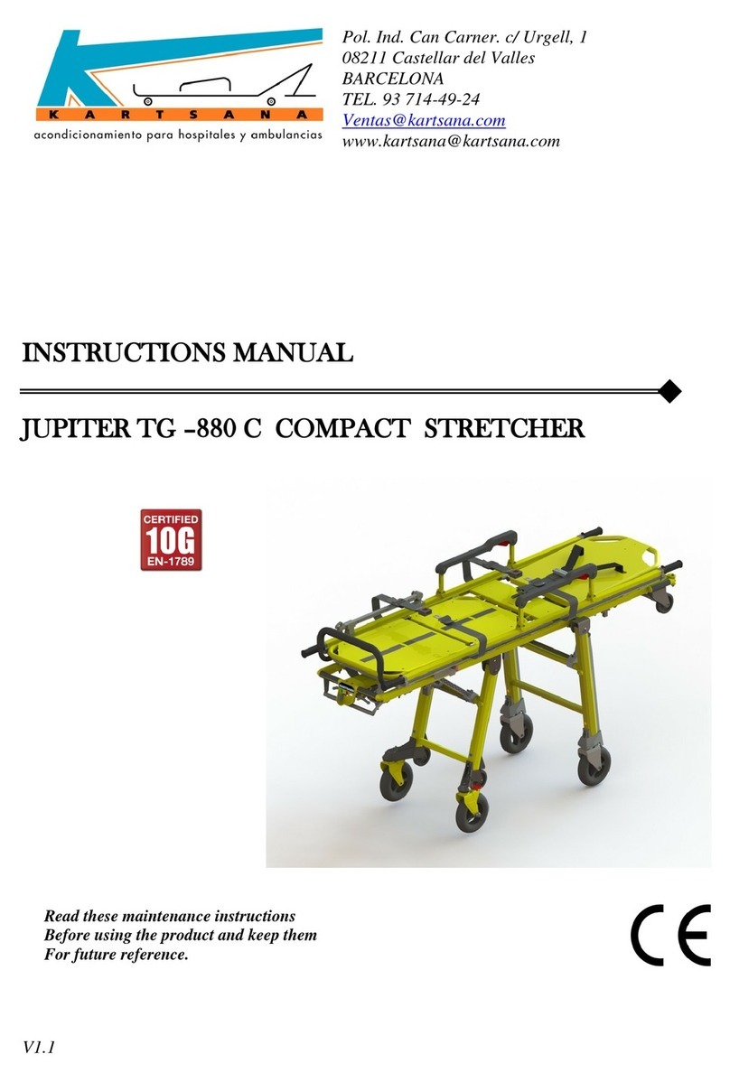
Kartsana JUPITER TG-880 C User manual

Kartsana
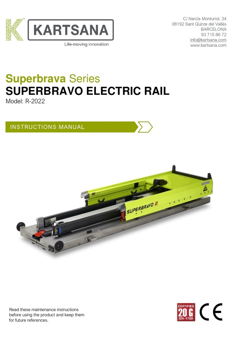
Kartsana SUPERBRAVO 2 User manual

Kartsana
Kartsana BRAVA TG-1000 User manual

Kartsana
Kartsana BRAVA TG-1000 User manual

Kartsana
Kartsana BRAVO 2 User manual

Kartsana
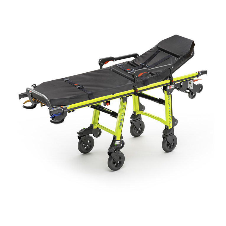
Kartsana TG-241 Series User manual

Kartsana
Kartsana Fuego TGR-244 User manual

Kartsana
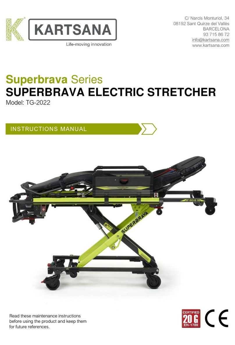
Kartsana SUPERBRAVA TG-2022 User manual

Kartsana
Kartsana TGE-241 Series User manual

Kartsana
Kartsana Superbrava Series User manual