Montage- und Sicherheitshinweise
Installation and Safety Instructions
Warnung / Warning
Gefahr durch elektrische Spannung! / Danger to life from electric shock!
●Gerät nicht öffnen oder daran manipulieren.
Do not open or tamper with the unit.
●Bei Arbeiten an der Anlage immer Netzstecker aus der Steckdose
ziehen.
When working on the system, always unplug the mains plug from
the socket.
●Um das Gerät allseitig ein Freiraum von min. 5cm lassen.
Ensure clearance of at least 5cm to all sides.
●Gerät nicht an der Decke montieren.
Do not mount the unit overhead.
●Um das Gerät eine freie Luftzirkulation sicherstellen.
Ensure free circulation of air to discharge the heat emitted by the unit.
●Zulässige Umgebungstemperatur: –20°C bis +50°C
Permissible ambient temperature: –20°C bis +50°C
●Auf das Netzgerät keine mit Flüssigkeit gefüllten Gegenstände
stellen.
Do not place any liquid-filled items on top of the power supply unit.
●Das Netzgerät nicht Tropf- oder Spritzwasser aussetzen.
Do not expose the power supply unit to dropping or splashing water.
●Sicherstellen, dass der Netzstecker ohne Schwierigkeiten zugäng-
lich und benutzbar ist.
Make sure that the power supply unit is easily accessible and operable.
●
Netzstecker ziehen, um das Gerät sicher vom Netz zu trennen.
Disconnect the unit from the mains to unplug it.
Achtung / Notice
Gefahr von Geräteschäden! / Risk of material damage!
●Gerät nur in trockenen Innenräumen und nicht auf oder an leicht
entzündlichen Materialien montieren.
Install the unit only in dry areas indoors. Do not install on or
against highly combustible materials.
●Gerät mit einer Potenzial-Ausgleichsleitung versehen
(Cu,mind.4mm2).
Make sure that the unit is provided with an earthing wire (Cu, at
least. 4mm2).
●Sicherheitsbestimmungen der jeweils aktuellen Normen
EN60728-11 und EN60065 beachten.
Comply with the safety regulations set out in the current
EN60728-11 and EN 60065.
●Befestigungsmittel: Holzschrauben, Ø max. 4,5 mm
Fixings: wood screws, max. Ø: 4.5mm
●Verbindungsstecker: HF-Stecker 75Ω (Serie F) gemäß EN61169-24
●Connectors: RF connector 75Ω (F series) according to
EN61169-24.
●Nicht benutzte Teilnehmerausgänge mit 75-Ω-Widerständen
abschließen, z.B. EMK 03.
Close unused subscriber ports by 75Ω resistors, e.g. EMK03.
●Nicht benutzte Kaskadenausgänge mit 75-Ω-Widerständen inkl.
DC-Blocker abschließen.
Terminate any unused trunk outputs with 75Ω resistors incl. DC
blocker.
●Nur Koaxialkabel mit einem maximalen Innenleiterdurchmesser
von 1,2mm und ohne Grat verwenden.
Only use coaxial cables with the max. Ø of the inner conductor of
1.2mm and without any burrs.
●Vor Inbetriebnahme die Anlage auf evtl. Kurzschlüsse der Koaxial-
kabel überprüfen. Darauf achten, dass die Eingangspegel der SAT-
Ebenen möglichst gleich hoch sind. Eine Power-LED zeigt den
Betrieb an. Die Stromzufuhr kontrollieren, wenn die Power-LED
nicht leuchtet.
Before commissioning, make sure there is no short circuit in the
coaxial cable. Ensure that the input levels are the same, if pos-
sible. A power LED shows the operation mode. If it is not on,
check the power source.
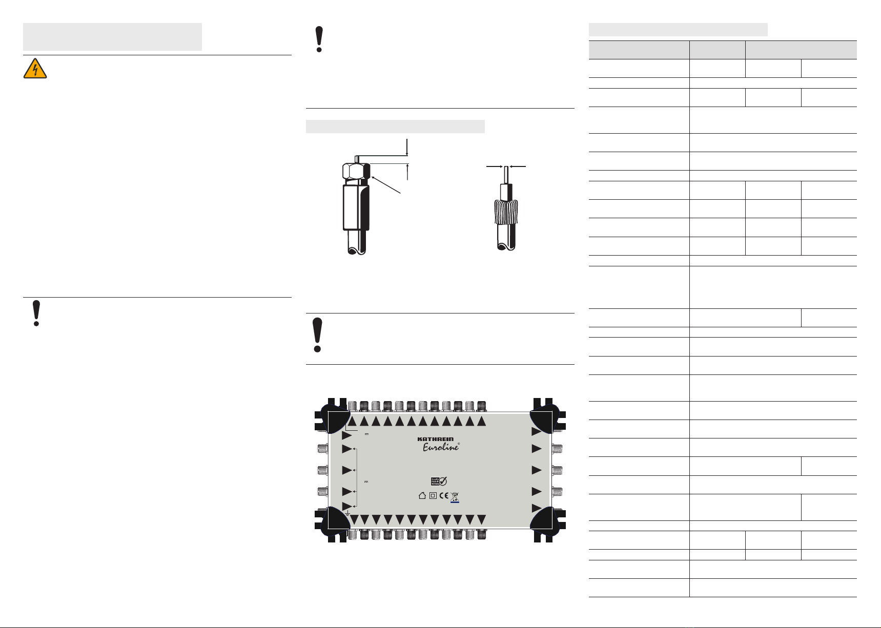
Installation / Installation
F-Stecker montieren / Connecting the F-type Connector
Abb. 2: F-Stecker montieren / Fig. 2: Connecting the F-type connector
Gerät anschließen / Connecting the unit
Anschlüsse gemäß dem Aufdruck installieren.
Connect according to the sticker on the device.
Elektrische Installationen nur durch geschultes Fachpersonal durchführen
lassen.
Make sure electrical installations are performed by qualified personnel.
DC
KEM 10524
20510109
DE - 83022 Rosenheim
23
9
1513 17 21
11
3715 19
10
2
614 18 22
12
4
816 20 24
T
V
H
Low
High
V
H
DC in
15 V 3.3 A max.
T
V
H
Low
High
V
H
15 V
Abb. 3 / Fig. 3: KEM10524
Technische Daten / Technical Data
Typ KEM10508 KEM10516 KEM
10524/10532
Bestellnummer
Order number 20510107 20510108 20510109
205101110
Eingänge/Inputs 4xSAT, 1xterr.
Teilnehmerausgänge
Subscriber Outputs 8 16 24/32
Eingangs- und Ausgangs-
impedanz / Input and output
impedance
75 Ω F-Female
Frequenzbereich SAT
Frequency range SAT 950–2400MHz
Frequenzbereich TER
Frequency range TER 40–862MHz
Kaskadenausgänge/Trunk outputs 5 (4SAT + 1xterr.)
Anschlussdämpfung SAT
Insertion loss SAT 1–3dB ±2dB 1–2dB ±2dB –2–1dB ±2dB
Anschlussdämpfung TER
Insertion loss TER 0dB ±3dB 0dB ±3dB –2dB ±2dB
Durchgangsdämpfung SAT
Through loss SAT –2dB ±1dB –2– –4dB
±1dB
–2––6dB
±2dB
Durchgangsdämpfung TER
Through loss TER –2dB ±1dB –2 ––3dB
±1dB –2dB ±2dB
Isolation TER/SAT typ. 30dB
Max. Ausgangspegel SAT (IMD3
35dB nach EN50083-3)
Max. output level SAT
(IMD335dB) according to
EN50083-3
101dBµV
Max. Ausgangspegel TER
Max. output level TER (IMD360dB) 84dBµV 91dBµV
Isolation H/V typ. 30dB
Eingangsanpassung SAT
Input return loss SAT >10dB
Eingangsanpassung TER
Input return loss TER >10dB
LNB-Versorgung
LNB supply voltage
Ext. Netzteil 15VDC / 3.3A oder Fernspeisespan-
nung über Kaskade / Ext. PSU 15VDC / 3.3A or
remote feed via trunk lines
Max. LNB-Versorgungsstrom
Max. LNB supply current 450mA
Ausgangsanpassung SAT
Output return loss SAT >10dB
Ausgangsanpassung TER
Output return loss TER >10dB
Stromverbrauch
Current consumption 35mA (from STB) 29mA (from
STB)
Externes Netzteil
External PSU
90–230VAC zu 15VDC 3,3 A: KEMP15, BN 20510131
90–230VAC to 15VDC 3.3 A: KEMP15, Order no. 20510131
Stromaufnahme vom ext. Netzteil
Current consumption from
ext. PSU
110mA 280mA
Schaltbefehle/Switch commands 13/18 V, 0/22 kHz, DiSEqC 1.0
Abmesssungen (LxBxH)
Dimensions (LxWxH) 140x140x63mm 220x140x63mm 240x140x63mm
Gewicht/Weight ~300 g ~500 g ~600 g
Betriebstemperaturbereich
Operating temperature range –20–50ºC
DC-Anschlusstyp
DC Connector type
DC-Netzteilbuchse 5,5/2,1mm
DC Jack 5.5/2.1mm
Max. 2 mm Überstand
Anzugsmoment max. 3,4 Nm
(Gefahr des Überdrehens)
Durchmesser
0,6 - 1,2 mm gratfrei
Max. 2 mm protrusion
Tightening torque max. 3,4 Nm
(risk of overtightening)
Diameter
0,6 - 1,2 mm burr free


