KEBCO COMBISTOP 38 User manual

COMBISTOP TYPE 38
INSTRUCTIONS FOR USE | INSTALLATION TYPE 38 SIZE 2...11
Translation of the original manual
Document 20228574 EN 04


3
PREFACE
Preface
The described devices or add-on parts are products of the KEB Automation KG. The
enclosed documents correspond to conditions valid at printing. Misprint, mistakes and
technical changes reserved.
Signal words and symbols
Certain operations can cause hazards during the installation, operation or thereafter.
There are safety informations in the documentation in front of these operations. Security
signs are located on the device or machine. A warning contains signal words which are
explained in the following table:
DANGER Dangerous situation, which will cause death or serious injury in case of
non-observance of this safety instruction.
WARNING Dangerous situation, which may cause death or serious injury in case of
non-observance of this safety instruction.
CAUTION Dangerous situation, which may cause minor injury in case of non-ob-
servance of this safety instruction.
NOTICE Situation, which can cause damage to property in case of non-obser-
vance.
RESTRICTION
Is used when certain conditions must meet the validity of statements or the result is
limited to a certain validity range.
Is used when the result will be better, more economic or trouble-free by following
these procedures.
More symbols
• / - Enumerations are marked with dots or indents.
=> Cross reference to another chapter or another page.
Note to further documentation.
www.keb.de/service/downloads

4
PREFACE
Laws and guidelines
the device nameplate or the signing that it complies with the essential safety require-
ments.
The EC declaration of conformity can be downloaded on demand via our website.
Warranty and liability
The warranty and liability on design, material or workmanship for the acquired device is
given in the general sales conditions.
www.keb.de/terms-and-conditions
Support
Through multiple applications not every imaginable case has been taken into ac-
count. If you require further information or if problems occur which are not treated de-
tailed in the documentation, you can request the necessary information via the local
KEB Automation KG agency.
The use of our units in the target products is outside of our control and therefore
lies exclusively in the area of responsibility of the customer.
advice in spoken and written and through tests, are made to best of our knowledge and
information about the intended use. However, they are regarded as being only informal
and changes are expressly reserved, in particular due to technical changes. This also
applies to any violation of industrial property rights of a third-party. Selection of our units
in view of their suitability for the intended use must be done generally by the user.
Tests can only be done within the intended end use of the product (application) by
the customer. They must be repeated, even if only parts of hardware, software or
Copyright
The customer may use the instructions for use as well as further documents or parts
from it for internal purposes. Copyrights are with KEB Automation KG and remain valid
in its entirety.
Other wordmarks or/and logos are trademarks (™) or registered trademarks (®) of their
respective owners.

5
TABLE OF CONTENTS
Table of Contents
Preface ....................................................................................................................................................3
Signal words and symbols .............................................................................................................3
More symbols.................................................................................................................................3
Laws and guidelines.......................................................................................................................4
Warranty and liability......................................................................................................................4
Support ........................................................................................................................................4
Copyright........................................................................................................................................4
Table of Contents ...................................................................................................................................5
List of Figures.........................................................................................................................................7
List of Tables ..........................................................................................................................................8
Glossary ..................................................................................................................................................9
Standards for mechanical components .............................................................................................10
1 Basic safety instructions .............................................11
1.1 Target group................................................................................................................................... 11
1.2 Transport, storage and proper use.............................................................................................. 11
1.3 Installation and mounting.............................................................................................................12
1.4 Electrical connection .................................................................................................................... 12
1.5 Start-up and operation ..................................................................................................................12
1.6 Maintenance...................................................................................................................................13
2 Product description..................................................... 14
2.1 Intended use .................................................................................................................................. 14
2.2 Residual risks ................................................................................................................................ 14
2.3 Improper use..................................................................................................................................14
2.4 Type code .......................................................................................................................................15
2.5 Type code magnet and magnet system.......................................................................................16
2.6 Overview COMBISTOP Type 38....................................................................................................17
2.7 Functional description .................................................................................................................. 17
3 Technical data .............................................................. 18
3.1 Operating conditions .................................................................................................................... 18
3.1.1 Climatic environmental conditions......................................................................................18
3.1.2 Electrical operating conditions............................................................................................18
3.2 Device data COMBISTOP 38.........................................................................................................19
3.2.1 Overview ............................................................................................................................19
3.3 Dimensions and weights .............................................................................................................. 20
3.3.1 Version without options ......................................................................................................20
3.3.2 Version with hand release ..................................................................................................21
3.3.3 Version with double brake ..................................................................................................22
3.4 Accessories ...................................................................................................................................24
3.4.1 Flange, friction disc ............................................................................................................24
3.4.2 Dust protection ring ............................................................................................................25
6
TABLE OF CONTENTS
4 Mounting....................................................................... 26
4.1 Notes on mounting........................................................................................................................26
4.1.1 Checks before mounting the brake ....................................................................................26
4.1.2 Observe during mounting...................................................................................................27
4.2 Mount brake ...................................................................................................................................27
4.2.1 Step 1: Mounting the hub ...................................................................................................28
4.2.2 Step 2: Mounting the lining.................................................................................................29
4.2.3 Step 3: Mounting the magnetic system ..............................................................................30
4.2.3.1 Check air gap X...............................................................................................................30
4.3 Microswitch (option) ..................................................................................................................... 31
4.3.1 Microswitch as armature position monitoring (default setting) ...........................................31
4.3.1.1 Checking the microswitch setting for armature position monitoring ................................ 31
4.3.2 Microswitch as wear control ...............................................................................................31
4.3.3 Adjustment and change of the microswitch........................................................................32
4.3.3.1 Dismounting ....................................................................................................................33
4.3.3.2 Mounting..........................................................................................................................33
4.3.3.3 Connecting the microswitch ............................................................................................33
4.3.3.4 Adjustment of the microswitch.........................................................................................34
5 Electrical connection................................................... 35
5.1 Connection of the brake ............................................................................................................... 35
5.1.1 AC side switching ...............................................................................................................36
5.1.1.1 Connection for AC side switching....................................................................................36
5.1.1.2 Connection in the terminal box for AC side switching .....................................................37
5.1.2 DC side switching...............................................................................................................38
5.1.3 DC and AC side switching .................................................................................................39
5.1.4 Protective earth ..................................................................................................................39
6 Start-up......................................................................... 40
6.1 Inspections prior to start-up of the brake ...................................................................................40
6.1.1 Visual inspection ................................................................................................................40
6.1.2 Load-free testing ................................................................................................................40
6.1.3 Run in of the brake.............................................................................................................40
6.1.3.1 Friction work switching frequency type N, H, D...............................................................41
7 Operation...................................................................... 42
7.1 Hand release (option)....................................................................................................................42
8 Troubleshooting........................................................... 43

7
TABLE OF CONTENTS
9 Maintenance and service ............................................ 44
9.1 Maintenance intervals ................................................................................................................... 44
9.2 Service............................................................................................................................................44
9.2.1 Dismount the brake ............................................................................................................44
9.2.2 Check air gap .....................................................................................................................45
9.2.2.1 Checking the air gap X....................................................................................................46
9.2.3 Readjust air gap .................................................................................................................47
9.2.4 Replacing the lining............................................................................................................48
9.2.5 Check the function hand release (option)...........................................................................48
9.2.5.1 Checking the adjustment dimension ...............................................................................49
10 Dismounting and Disposal ....................................... 50
10.1 Dismounting.................................................................................................................................50
10.2 Disposal........................................................................................................................................50
................................................................ 51
11.1 EU declaration of conformity...................................................................................................... 51
...............................................................................................................................53
12 Revision history......................................................... 56

8
LIST OF FIGURES
List of Tables
List of Figures
Figure 1: Overview COMBISTOP Type 38......................................................................................17
Figure 2: Dimensions COMBISTOP Type 38 without options.........................................................20
Figure 3: Dimensions COMBISTOP Type 38 hand release ............................................................21
Figure 4: Dimensions COMBISTOP Type 38 double brake ............................................................22
..................................................24
Figure 6: Dimensions COMBISTOP Type 38 dust protection ring ..................................................25
Figure 7: Mounting the hub on the motor shaft ...............................................................................28
Figure 8: Consideration of the axial clearance of the motor shaft...................................................28
Figure 9: Mounting the lining...........................................................................................................29
Figure 10: Mounting the magnetic system ........................................................................................30
Figure 11: Changing the microswitch................................................................................................32
Figure 12: Strands for the microswitch..............................................................................................33
Figure 13: Adjustment of the microswitch .........................................................................................34
Figure 14: Connection for AC side switching ....................................................................................36
Figure 15: Connection in the terminal box for AC side switching......................................................37
Figure 16: Connection for DC side switching....................................................................................38
Figure 17: Connection for DC and AC switching...............................................................................39
Figure 18: Friction work switching frequency type N, H, D ...............................................................41
Figure 19: Operation of the hand release .........................................................................................42
Figure 20: Dismount the brake..........................................................................................................44
Figure 21: Checking the air gap........................................................................................................46
Figure 22: Adjustment dimension "m" of the hand release ...............................................................49
............................................................................................52
...................................................................................................................55
Table 1: Type code ........................................................................................................................15
Table 2: Type code magnet and magnet system...........................................................................16
Table 3: Climatic environmental conditions ...................................................................................18
.........................................................................................................18
Table 5: Device data COMBISTOP Type 38..................................................................................19
Table 6: Dimensions COMBISTOP Type 38 double brake ............................................................23
..................................................25

Table 8: Pre-assembled connection cables...................................................................................35
Table 9: Run in of the brake...........................................................................................................40
Table 10: Troubleshooting ...............................................................................................................43
Table 11: Check air gap...................................................................................................................45
Table 12: Check the function hand release .....................................................................................48

9
GLOSSARY
Glossary
0V Earth-potential-free common point
1ph 1-phase mains
3ph 3-phase mains
AC AC current or voltage
Application The application is the intended use
of the KEB product.
AWG American wire gauge
B2B Business-to-business
Customer The customer has purchased a KEB
product from KEB and integrates the
KEB product into his product (cus-
tomer product) or resells the KEB
product (dealer)
DC DC current or voltage
DIN German Institut for standardization
EMC Electromagnetic compatibility
EN European standard
End customer The end customer is the user of the
customer product.
FE Functional earth
GND Reference potential, ground
IEC International standard
IP xx Degree of protection (xx for level)
KEB product The KEB product is subject of this
manual.
Manufacturer The manufacturer is KEB, unless
-
nufacturer of machines, engines,
vehicles or adhesives).
MCM American unit for large wire cross
sections
MTTF Mean service life to failure
NN Sea level
PE Protective earth
PELV Protective Extra Low Voltage
SELV Safety Extra Low Voltage (<60 V)

10
STANDARDS FOR MECHANICAL COMPONENTS
Standards for mechanical components
VDE0580 Electro magnetic devices and components
DIN46228-1 Tubular end-sleeves without plastic sleeve
DIN46228-4 Tubular end-sleeves with plastic sleeve
DINIEC60364-5-54 Low-voltage electrical installations - Part 5-54: Selection and erection of
electrical equipment - Earthing arrangements, protective conductors and protec-
tive bonding conductors
EN60204-1 Safety of machinery - Electrical equipment of machines - Part 1: General requi-
rements (IEC 44/709/CDV)
EN60529 Degrees of protection provided by enclosures (IP Code) (IEC 60529)
EN60664-1 Insulation coordination for equipment within low-voltage systems - Part 1:
Principles, requirements and tests (IEC 60664-1)
environmental parameters and their severities - Section 1: Storage (IEC 104/648/CD)
environmental parameters and their severities - Section 2: Transportation and
handling (IEC 104/670/CD)
environmental parameters and their severities; section 3: Stationary use at
weatherprotected locations (IEC 60721-3-3)
DIN 748-3 Cylindrical shaft ends - Part 3: For rotating electrical machinery
frame size larger then 315 - Tolerances, test
DIN EN 50347 General purpose three-phase induction motors having standard dimensions and
DIN 6885-1 Drive type fastenings without taper action, parallel keys, keyways - Deep pattern
DIN 6885-3 Drive type fastenings without taper action, parallel keys, keyways - Low pattern
DIN 332-2 Center holes 60° with thread for shaft ends for rotating electrical machines

11
BASIC SAFETY INSTRUCTIONS
1 Basic safety instructions
The following safety instructions have been created by the manufacturer for the area
-
the loss of any liability claims.
NOTICE Hazards and risks due to ignorance.
Read the instructions for use!
Observe the safety and warning instructions!
If anything is unclear, please contact KEB!
1.1 Target group
• Knowledge and understanding of the safety instructions.
• Skills for installation and assembly, start-up, operation and maintenance of the product.
•
• Detection of hazards and risks of the drive technology.
• Knowledge about work safety and accident prevention (e.g. DIN 6885-3).
1.2 Transport, storage and proper use
Immediately report transport damages to the transport company and the manufacturer.
Depending on its design and weight appropriate lifting devices must be used for han-
dling.
NOTICE Damage due to improper storage.
In case of improper storage, no liability is assumed for resulting damages.
Don't storage devices or parts
• in the environment of aggressive and/or conductive liquids or gases.
• with direct sunlight.
•
• in environments that can lead to corrosion and contamination.

12
BASIC SAFETY INSTRUCTIONS
1.5 Start-up and operation
The operation must not be started until it is determined that the installation complies with
the machine directive; Account is to be taken of EN 60204-1.
CAUTION
Pay attention to friction work (speed and the frequency of operation)!
Loss or decrease of braking torque!
of the lining or magnet and to severe signs of wear on the gearing of
the hub and lining. This can lead to failure of the brake (=> „6.1.3.1
Friction work switching frequency type N, H, D“).
1.3 Installation and mounting
NOTICE
Before installation, make sure that the drive is load-free.
Secure drive against rotation.
Consider the following installation measures to prevent faults
Do not operate the brake in an explosive environment.
Provide measures against freezing or ice formation on the friction surfaces.
Take appropriate measures against high air humidity, aggressive vapours/liquids or
similar that lead to corrosion and 'rusting' of the pole surfaces.
1.4 Electrical connection
DANGER Electrical voltage at brake and motor!
Danger to life due to electric shock!
Any work on the electrical power supply may only be carried out by
-
age and secure it against switching on.
Never bridge upstream protective devices, not even for test purposes.
Standard-compliant testing of the protective conductor connection to
all touchable metal parts.

13
BASIC SAFETY INSTRUCTIONS
1.6 Maintenance
Secure the brake against being switched on accidentally during maintenance work.
Make the brake load-free during maintenance work to avoid uncontrolled move-
ments.
Protection against the ingress of foreign particles into the air gap. These can im-
pede the movement of the rotor and armature.
When carrying out maintenance and repair work, the brake must not be energised.
The brake lining must not come into contact with cleaning agents or solvents.
In case of malfunction, unusual noises or smells inform a person in charge!
DANGER
Unpredictable malfunctions!
Only use original manufacturer parts.
Infringement will annul the liability for resulting consequences.
CAUTION High temperatures due to braking
Burning of the skin!
Cover hot surfaces safe-to-touch.
If necessary, attach warning signs on the system.
Check the temperature and let the brake cool down if necessary.
CAUTION Rotating Parts
Shock or crushing of body parts!
Wear protective goggles against ejected parts and dirt particles,
Take measures against being pulled into the machine.
NOTICE Malfunctions of the brake!
impair the function of the brake.

14
PRODUCT DESCRIPTION
2 Product description
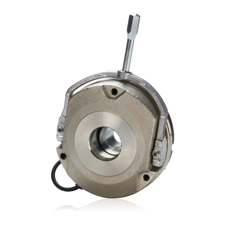
The COMBISTOP type 38 brake is an electromagnetically actuated dual-surface
spring-applied brake for dry running.The standard series of dual-surface spring-applied
brakes are COMBISTOP N and H in two versions.
The brakes are optionally designed for dynamic applications with braking processes at
high speed (COMBISTOP N) and for static applications, i.e. braking at speeds and safe
holding of loads (COMBISTOP H).
manually opened even in the event of a malfunction.
COMBISTOP D stands for double safety and includes a series of double brakes pre-
pared for tasks with redundant brake circuits. The mechanical design with two com-
pletely independent safety spring-applied brakes meets the requirements of DIN 56950
(BGV C1).
The brakes are delivered ex works with preset air gaps ready for installation. Extensive
design measures reduce switching and running noise to a minimum.
2.1 Intended use
Spring-applied brakes are used to brake rotating masses or to hold shafts.
The operational reliability of the brake is only guaranteed when used according to spec-
-
ble risks and is solely and exclusively the responsibility of the operating company.
The technical data and the information on the connection conditions must be taken from
the nameplate and the instructions for use and must be observed. Any use beyond the
The actual use of the brake in the target products is beyond KEB Automation KG's con-
trol and, therefore, shall be exclusively within the operating company's responsibility.
Restriction
If the product is used in machines which work under exceptional conditions or if essen-
the necessary reliability and security must be ensured by the machine builder.
2.2 Residual risks
The brake can overheat or be damaged due to wrong design, improper handling or
changed operating requirements. This may lead to failure of the brake.
2.3 Improper use
Improper use exists, if
•
• unauthorized structural changes have been made to the brake.
• improper repairs have been carried out.
• the product has been incorrectly installed or serviced.
KEB Automation KG expire.

15
PRODUCT DESCRIPTION
2.4 Type code
The type designation and the version can be taken from the nameplate or the marking.
x x 3 8 x x x - x x x x
Variant Customer versions
Design
N/DEN: Dynamic application
H/DEH: Static application
DDN/
DDH: Double brake 1)
Hand release 11: Without hand release
13: With hand release
Type COMBISTOP Type 38
Size 02…11
Table 1: Type code
1) Supplied with ready-to-install presetting of the air gaps.
The complete material number is not printed on the brake. Only the magnet is
marked with a material number. An assignment of the coupling based on the
magnet marking is only possible to a limited extent.

16
PRODUCT DESCRIPTION
2.5 Type code magnet and magnet system
Magnet designation can be taken from the signing.
x x 0 3 x x x - x x x x
Strands Material and length
Voltage e.g. DC 24V
Version
100/0NN: Dynamic application
10H/00H: Static application
Type COMBISTOP Type 38
Size 02…11
Table 2: Type code magnet and magnet system

17
PRODUCT DESCRIPTION
2.6 Overview COMBISTOP Type 38
➀
Legend
A Size 02 to 06 2a/2b Hub
B Size 07 to 11 3a/3b Lining
1 Magnet system 4 Friction disc (optional) 1)
1.1 Magnet 5 Flange (optional) 2)
1.2 E-piece (adjusting piece) 6 Hand release (optional)
1.3 Armature 7 Dust protection ring (optional)
Figure 1: Overview COMBISTOP Type 38
1) Frictiondiscoptionalandalternativetotheange.
2) Flange optional and alternative to the friction disc.
2.7 Functional description
The braking force is generated in de-energised state by pressure springs which press
the armature and the lining against the friction surfaces. The lining is twist-proof but can
be axially moved while connected to the shaft.
attracts the armature against the spring force. In this way, the linings are released and
the shaft can rotate freely.
After disconnecting the voltage, the armature is de-energised. The pressure springs
press the armature against the linings which generate the braking torque on the friction
surfaces. This allows for decelerating downstream elements.

3 Technical data
3.1 Operating conditions
3.1.1 Climatic environmental conditions
Operation Standard Class Notes
Ambient temperature VDE 0580 –-5...35°C (standard)
-40...35°C (CCV: Cold Climate Version)
Construction and degree of
protection EN 60529 IP40 Standard
IP44 With dust protection ring
Table 3: Climatic environmental conditions
3.1.2 Electrical operating conditions
Requirement Standard Class Notes
Overvoltage category EN 60664-1 III –
Table 4: Deviceclassication
18
TECHNICAL DATA

19
DEVICE DATA COMBISTOP 38
3.2 Device data COMBISTOP 38
3.2.1 Overview
Device size 02 03 04 05 06 07 08 09 10 11
Rated torque after
running-in at 20 °C
N version
1) M2N / Nm 5 10 20 36 70 100 150 250 500 1000
Rated torque after
running-in at 20°C
H version
1) M2N / Nm 7.5 15 30 50 90 150 225 375 750 1500
Rated power N version
P20 / W 25 30 30 48 62 65 75 80 130 180
Rated power H version
P20 / W 25 30 30 48 75 90 90 115 180 280
Rated voltage 2) UN_dc / V 24/105/ 180 / 205 3)
Cyclic duration factor ED / % 100
Speed for service
braking n/ rpm 3000 1500
Max. speed for
emergency braking
n_max /
rpm 6000 5000 4500 3500 3000 2000
Mass moment of inertia
J/ 10-3kgm² 0.025 0.075 0.227 0.553 0.771 1.84 6.17 17.22 45.28
153.6
Nominal air gap X/ mm 0.2 0.3 0.4 0.5 0.6
Switching cycles for
4) SC1 / rpm 60 25 5 2 1
Switching cycles for
4) SC2 / rpm 120 75 75 50 10 5 3 2
Switching cycles with
power box DC SC3 / rpm 55 40 40 25 5 2 1 ─
Separation time 5) t2/ ms 40 55 90 110 240 220 320 350 400 750
Separation time with
power box
5) t2/ ms 20 35 50 60 120 120 150 170 180 ─
Response delay AC 6) t11_ac / ms 70 100 180 220 260 400 700 900 1400 3100
Response delay DC 6) t11_dc / ms 10 15 25 25 25 40 50 60 100 450
Engagig time AC 7) t1_ac / ms 100 150 200 240 330 650 900 1200 2000 3500
Engaging time DC
7) t1_dc / ms 20 30 50 55 90 120 180 220 300 1000
Feather key according to DIN 6885-1
Keyway
ISO class B (optional F and H)
Table 5: Device data COMBISTOP Type 38
1) Thetorquesarebasedonaquasi-staticmeasurementwithadierentialspeedof25rpm.
2) Special voltage upon request.
3) 105 V / 180 V / 205 V fall under the Low-Voltage Directive => „11.1 EU declaration of conformity“.
4) Maximum permissible switching cycles for DC-switching, continuous operation (100 % ED) and max.
operating temperature of 80 °C.
5) Separation time from switching on the current to the beginning of the torque drop. The values are to be
regarded as guidelines.
6) Timefromswitchingothecurrentuntilincreaseintorque.Thevaluesaretoberegardedasguidelines.
7) Timefromswitchingothecurrentuntilreaching0.9xratedtorqueM2N. The values are to be regarded as
guidelines.

20
DIMENSIONS AND WEIGHTS
3.3 Dimensions and weights
3.3.1 Version without options
A
02…1138N/H-xxxx
Size
Dimensions / mm Weight / kg
A B D
max. E G H K L N P U 3811N/H
02 85 72 15 1) 22 34.2 1-1.5 22 37.7 18 3x4.2 60 1
03 102 90 20 32 37.2 2-2.5 31 41.7 20 3x5.3 77 1.5
04 127 112 25 38 47.2 2-2.5 37 51.7 20 3x6.5 96 3
05 147 132 30 42 52.7 2.5-3 42 57.7 25 3x6.5 115 4.5
06 164 145 35 1) 47 59.8 2.5-3 42 68.8 30 3x8.5 115 7
07 190 170 45 62 68 3 57 75.5 30 3x8.5 149 10
08 218 196 60 78 80 4.5 57/76 2) 87.4 35 3x8.5 175 16
09 253 230 60 97 88.2 5 76 101.7 40 3x10.5 206 26
10 307 278 75 120 98.8 9.5 92 110.8 50 6x10.5 252 39
11 363 325 90 140 122.1 134.5 100 6x12.5 300 80
Figure 2: Dimensions COMBISTOP Type 38 without options
1) Keyway according to DIN 6885-3.
2) With hub bore >Ø45.
Other manuals for COMBISTOP 38
3
Table of contents
Other KEBCO Industrial Equipment manuals

KEBCO
KEBCO Combivert R6 User manual

KEBCO
KEBCO COMBICOM User manual

KEBCO
KEBCO COMBIVERT F6 User manual

KEBCO
KEBCO COMBINORM B User manual

KEBCO
KEBCO COMBIVERT S6 Series User manual

KEBCO
KEBCO COMBILINE User manual

KEBCO
KEBCO COMBILINE E6 Series User manual

KEBCO
KEBCO COMBINORM User manual

KEBCO
KEBCO COMBIVERT G6 User manual

KEBCO
KEBCO COMBISTOP User manual