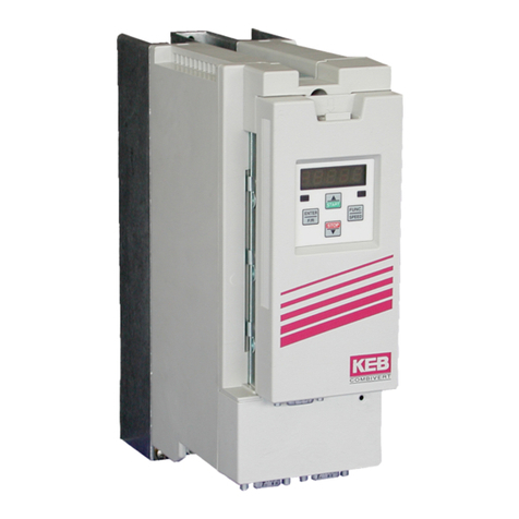
KEBCO COMBICOM User manual


GB - 3
Inhaltsverzeichnis
1. Introduction......................................................................................................................5
1.1 General information.......................................................................................................................... 5
1.2 Validity ............................................................................................................................................... 5
1.3 Qualication ...................................................................................................................................... 5
1.4 Order data.......................................................................................................................................... 6
1.5 Product description.......................................................................................................................... 6
1.6 List of literature................................................................................................................................. 6
2. Description of the Hardware...........................................................................................7
3. Software ...........................................................................................................................8
3.1 Fundamentals of the KEB-Powerlink connection.......................................................................... 8
3.1.1 EPL-Command-Layer protocol(parameter channel)........................................................................... 8
3.1.2 Set-addressing with subindex............................................................................................................. 9
3.2 Process data communication.......................................................................................................... 9
3.2.1 Functionality........................................................................................................................................ 9
3.2.2 Synchronous mode........................................................................................................................... 10
3.2.3 Fieldbus watchdog.............................................................................................................................11
3.2.4 SupportofDSP402prole .................................................................................................................11
4. Operator Parameters.....................................................................................................12
5. Annex 17
5.1 Operator Parameters ...................................................................................................................... 17
5.2 DSP402-Parameter.......................................................................................................................... 18
5.3 UnitdesciptionbyXMLles .......................................................................................................... 18
5.4 Integration of the KEB-F5 Powerlink drive in the Automation Studio of the B&R company... 19
5.4.1 Integration as Generic Powerlink Station.......................................................................................... 19
5.5 Display of the KEB parameter address with COMBIVIS.............................................................. 21

GB - 4

GB - 5
Powerlink Operator
1. Introduction
1.1 General information
Before working with the unit the user must become familiar with it. This includes especially the knowledge and
observance of the safety and warning directions. The pictographs used in this instruction manual have following
meaning:
Danger Indicates danger to life by electric current.
Warning Indicates possible danger to life or danger of injury.
Note Indicates tips and additional information.
1.2 Validity
ThismanualaswellasthespeciedhardwareandsoftwarearedevelopmentsoftheKarlE.BrinkmannGmbH.
Errorsandommissionsexcepted!ThecompanyKarlE.BrinkmannGmbHestablishedthisdocumentationtothe
bestofherknowledgebutwithoutengagement,thatthehereinstatedspecicationsmaynotprovidetheuserwith
theexpectedadvantagesThecompanyKarlE.BrinkmannGmbHreservestherighttochangethespecications
withoutpriornoticationorfurtherobligation.Allrightsreserved.
Theinformationcontainedinthetechnicaldocumentation,aswellasanyuser-specicadviceinspokenandwrit-
tenandthroughtests,aremadetobestofourknowledgeandinformationabouttheapplication.However,they
are considered for information only without responsibility. This also applies to any violation of industrial property
rights of a third-party.
Inspection of our units in view of their suitability for the intended use must be done generally by the user. Inspec-
tions are particulary necessary, if changes are executed, which serve for the further development or adaption of
our products to the applications (hardware, software or download lists). Inspections must be repeated completely,
evenifonlypartsofhardware,softwareordownloadlistsaremodied.
Inspection by
the user
Application and use of our units in the target products is outside of our control and
therefore exclusively in the area of responsibility of the user.
Use under spe-
cial conditions
The used semiconductors and components of KEB are developed and dimensioned
for the use in industrial products. If the KEB COMBIVERT is used in machines, which
work under exceptional conditions or if essential functions, life-supporting measures
oranextraordinarysafetystepmustbefullled,thenecessaryreliabilityandsecurity
must be ensured by the machine builder.
1.3 Qualication
Allworkfromthetransport,toinstallationandstart-upaswellasmaintenancemayonlybedonebyqualied
personnel(IEC364and/orCENELECHD384orDINVDE0100andnotenationalsafetyregulations).According
tothismanualqualiedstaffmeansthosewhoareabletorecogniseandjudgethepossibledangersbasedon
their technical training and experience and those with knowledge of the relevant standards and who are familiar
withtheeldofpowertransmisssion(VDE0100,VDE0160(EN50178),VDE0113(EN60204)aswellasthose
who note the valid local regulations).
Danger by high
voltage
KEB electronic components contain dangerous voltages, which can cause death or
serious injury. Depending on the protective system they can have live parts, bright
parts, if necessary also moving parts, as well as hot surfaces during operation.
Care should be taken to ensure correct and safe operation to minimise risk to personnel
and equipment.

GB - 6
Powerlink Operator
1.4 Order data
F5-Powerlinkoperator: 00.F5.060-H000
Additional components for the diagnostics interface:
HSP5cablebetweenPCandF5-Powerlinkoperator: 00.F5.0C0-0001
Adapter of DSUB to Western: 00.F5.0C0-0002
1.5 Product description
KEB power transmission develop, produce and sell static frequency inverters worldwide in the industrial power
range. The inverters of the type F5 can be equipped optionally with a Powerlink-controlled-node-interface. The
F5-PowerlinkoperatorisintegratedintotheFI-housingbysimpleplug-inandtsintoallF5-units.Hereitconcerns
to an intelligent interface which controls the data transfer from Powerlink to the FI control and reverse.
1.6 List of literature
[1]:EthernetPowerlinkV2.0CommunicationProle,DraftStandardVersion1.0.0
[2]:CANopenApplicationLayerandCommunicationProleDS301V4.02
[3]: Application manual of the used FI control.
[4]:CANopenDeviceproledrivesandmotioncontrolDSP402V2.0
[5]: Ethernet Powerlink V2.0 XML Device description, EPSG Draft Standard 1311 V1.0.0

GB-7
Powerlink Operator
2. Description of the Hardware
X6B
X6C X6D
Diagnose
PowerLink
FUNC
START
ENTER
STOP
PowerLink-Mailbox active
EPL_Link1
EPL_Link0
FU-Error
EPL_Error
Port0
EPL_Status
Port1
Node-Switch
x16 x1
Uext
(24V)
+
Powerlink Command-Layer active: Flashes, as long as the parameter channel communication is active.
EPL_Link0: Flashes, if a link is recognized at Powerlink-Port0. Flashes in case of activity on this port.
EPL_Link1: Flashes, if a Link is recognized at Powerlink-Port1. Flashes in case of activity on this port.
FU-Error: Red LED as copy of the FI error LED:
LED example Description
constantly off No voltage supply at FI control circuit
blinking FI control in error status
constantly on No error
EPL_ERROR:RedLEDinaccordancewiththespecication"ERRORLed`inthePowerlinkspecication([1]):
LED example Description
constantly off No error
constantly on Active error status

GB - 8
Powerlink Operator
EPL_STATUS:RedLEDinaccordancewiththespecication"STATUSLed`inthePowerlinkspecication([1]):
LED example Description
constantly off NMT_GS_OFF, NMT_GS_INITIALISATION,
NMT_CS_NOT_ACTIVE
cyclicickeringwithON(50ms)/OFF(50ms) NMT_CS_BASIC_ETHERNET
single lightning with ON(200ms) / OFF(1000ms) NMT_CS_PREOPERATIONAL_1
double lightning with ON(200ms) / OFF(200ms) /
ON(200ms) / OFF(1000ms)
NMT_CS_PREOPERATIONAL_2
triple lightning with ON(200ms) / OFF(200ms)
/ ON (200ms) / OFF(200ms) / ON (200ms) /
OFF(1000ms)
NMT_CS_READY_TO_OPERATE
constantly on NMT_CS_OPERATIONAL
cyclicashingwithON(200ms)/OFF(200ms) NMT_CS_STOPPED
X6B: RJ45 socket of the diagnostic interface (Combivis):
Attention !!! To prevent the damage of the serial interface on your Personal Computer be sure that you use the
specialHSP5cablefromKEBforconnectingyourPCtotheserialinterfaceoftheModBusoperator.
X6C,X6D: Standard Ethernet-RJ45-connector in accordance with IEEE 802.3 100Base-T:
3. Software
3.1 Fundamentals of the KEB-Powerlink connection
The KEB-F5-Powerlink operator contains a separate Powerlink slave controller for processing of time-critical
communication tasks. An extensive Powerlink compatibility is also ensured by using this external component. The
supported Powerlink versions are EPL V1 and EPL V2.
Technical data of the Powerlink interface:
Supported Powerlink version(s) EPL V1, EPL V2
Response Time 2 µs
3.1.1 EPL-Command-Layer protocol(parameter channel)
The Command-Layer-protocol’ is supported by the KEB-F5-Powerlink operator. Thus it is possible to address any
parameter itself in the FI control and in the Powerlink operator via acyclic SDO protocol. The supported services
onthe"COMMANDLayer"are:
Expedited Download Transfer with Write-by-Index as Server (writing of a parameter via index, subindex)•
Expedited Upload Transfer with Read-by-Index as Server (reading of a parameter via index, subindex)•
Parameter-addressing with 16-Bit index plus 8-Bit subindex
1.Index Last index Description
1000h 1FFFh Communicationparameterinaccordancewith[2]
2000h 5FFFh Parameter of FI control and operator with index = KEB-Parameter-Address +
2000h(*1). KEB uses he subindex for set-addressing.
6000h 9FFFh ParameteroftheunitproleDSP402inaccordancewith[4]
(*1):TheKEBparameteraddresscanbefoundhereorin[3].ItisalsopossibletodisplaytheKEBparameter
addressintheKEBstart-upsoftwareCOMBIVIS.Seeannexforspecicinformations.

GB - 9
Powerlink Operator
3.1.2 Set-addressing with subindex
The subindex is used for set-addressing at KEB parameters (Index = 2000h...5FFFh). The following coding is
valid:
Subindex Description
0 Indirect set-addressing: The addressed set is determined by the respective set indicator. Pa-
rameter Fr.09 is used for parameters of the FI control
1 Direct set-addressing of set 0
2 Direct set-addressing of set 1
4 Direct set-addressing of set 2
8 Direct set-addressing of set 3
16 Direct set-addressing of set 4
32 Direct set-addressing of set 5
64 Direct set-addressing of set 6
128 Directset-addressingofset7
Withthisbitcodingitisgenerallypossibletoresponseseveralsetswithonecommand.Howeverthisshouldnot
be used at read access, because an error code is returned, if not all values in the addressed sets are equal. This
multiple set-addressing can be used without problems for the illustration of the process PDOCUT data (Rx-PDO).
The same reservation (like reading via SDO commands) applies to the PDIN data illustration.
3.2 Process data communication
New process output data (PDOUT) can be sent to the KEB Powerlink slave and the actual process input data
(PDIN) can be determined by means of process data communication. Which parameters concern to the data is
determined by the process data illustration in the Powerlink operator. Up-to-date a maximum of 8 byte process
data for each data direction can be transferred.
3.2.1 Functionality
Process data mapping
The process data mapping is located in the Powerlink operator. The default setting for this is:
PDOUT data ( Powerlink-Master KEB-Slave ):
Byte0 Byte1 Byte2 Byte3 Byte4 Byte5 Byte6 Byte7
SY.43: Control word (long) SY.52: Set speed IN.22: User Parameter 1
LSByte MSByte LSByte MSByte LSByte MSByte
PDIN data ( KEB-Slave * Powerlink-Master ):
Byte0 Byte1 Byte2 Byte3 Byte4 Byte5 Byte6 Byte7
SY.44: Status word (long) SY.53: Actual Speed IN.22: User Parameter 1
LSByte MSByte LSByte MSByte LSByte MSByte
The mapping is adjustable as well as Powerlink parameters with index = 1600h and 1A00h and via operator pa-
rameters PD_Inx_Map and PD_Outx_Map (see below).
AmappingentryaccordingtoPowerlinkspecicationforobjects(1600h,1A00h)isbasedonthefollowing:
b63 b48 b47b32 b31 b24 b23 b16 b15 b0
BitLength BitOffset Reserved Subindex Index

GB - 10
Powerlink Operator
ThedefaultsettingofthemappingparametersaccordingtothePowerlinkcoding(s.[1])isasfollows:
Index Subindex Value
1600h 0 3
BitLen BitOffs Res. SI Index
1600h 1 0020 0000 00 01 202Bh
1600h 2 0010 0020 00 01 2034h
1600h 3 0010 0030 00 01 2E16h
1A00h 0 3
BitLen BitOffs Res. SI Index
1A00h 1 0020 0000 00 01 202Ch
1A00h 2 0010 0020 00 01 2035h
1A00h 3 0010 0030 00 01 2E16h
Note:
The internal structure of mapping-parameters (PD_Inx_Map, PD_Outx_Map) does not support the attribute ‚Bi-
tOffs’. Therefore the BitOffs is related to the order of the mappings.
I.e.: BitOffs(1) = 0
BitOffs(2) = BitLen(1)
BitOffs(3) = BitOffs(2) + BitLen(2)
BitOffs(4) = BitOffs(3) + BitLen(3)
ATTENTION !!! The process data of the structure 1*32-Bit + 1-2 times 16-Bit for output data and input data must
follow for the synchronous mode.
Finally, after changing the mappings, the number of the mapped objects (Subindex=0) must be written via mail-
box-command-layer(SDO)intherespectivemappingobject(1600hor1A00h,s[2])inorderthattheprocess
data processing becomes active.
3.2.2 Synchronous mode
The Powerlink SoC-Interrupt is used as synchronization signal for internal communication between Powerlink
operator and FI control in this special kind of communication. The synchronous mode causes a process data as-
signmentaccordingtotherulesspeciedabove.ThereceiptofanSoCinterruptisreferredasSYNCeventinthe
followingdocumentation.Theoperatordisplayisxedto‚Synch‘inthesynchronousmode.
This special communication mode causes some restrictions in the functionality of the Powerlink operator. To the
mentioned display also the keyboard is inactive.
The diagnostic interface remains in operation. The adjusted synchronous cycle time can be read off via diagnostic
interface at operator parameter FB.00: ComCycle.
The PDOUT data are transferred to the FU control and the current PDIN data to Powerlink are updated during
each synchronous cycle.

GB - 11
Powerlink Operator
ThePowerlinkoperator(atHS_SyncToutMode!=0)changesintoautomaticsynchronousmodeifthesynchro-
nous mode is activated, but no SoC interrupts are received. This is displayed in the operator display:
Thus the operator simulates itself the SoC interrupts time controlled in the adjusted Synch cycle time. The time-
out-time when changing into automatic synchronous mode is in standard 4 * SYNC cycle time (Com Cycle).
The operator switches only into synchronous-mode , if
• Processdata-mappinginbothdirectionfollowsthestructure1*32-Bit+1-2*16-Bitis.
• Bit"EnableSyncMode"isactivatedinoperatorparameter"FBSCong".
3.2.3 Fieldbus watchdog
TheeldbuswatchdogisamonitoringfunctionofthePowerlinkoperator.Theeldbuswatchdogservestoplace
the FI control into error status (E.BUS or A.BUS) if special communication events do not appear cyclically. Two
operatorparameters(Watchdoginhibit,Watchdogactivation)congurethewatchdogatoperatorside.Further-
moreparametersPn.05,Pn.06mustbesetintheFUIcontrolinordertodenethetimeout-timeandthereaction
to carry out in a timeout-case.
ThePowerlinkoperatormonitorestheoccurrenceoftheconguratedeldbusevents(Watchdoginhibit).These
eventsresetthewatchdog-timer.Severaleldbuseventscanbedenedasreset-event.Theoperatorinstructs
theFIcontrolviaaspecialcommandifthewatchdogtimecountsdownwithoutatleastoneofthecongurated
eldbusevents.TheFIcontrolreactionisdeterminedbyparametersPn.05,Pn.06(alreadymentioned).Theco-
dingofthesetwoparameterscanbetakenfrom[3].
3.2.4 SupportofDSP402prole
TheKEB-F5-PowerlinkoperatorsupportssomeelementaryobjectsoftheDSP402prole.Thisparametersare
denedin[4].Onlythevelocitymodeisintegrated.Alistoftheseparameterscanbefoundintheannexe.

GB - 12
Powerlink Operator
4. Operator Parameters
The operator parameters are managed by the Powerlink operator. Access to this parameters can be done through
diagnosis-interface with KEB-COMBIVIS software or through the SDO channel of Powerlink. The following list
containes only those parameters which are important for the user. . All other parameters are for debugging-purpo-
ses and have not to be changed by the user.
Name: Com_Cycle (Fb00)
Meaning: Indicates the adjusted SoC interrupt cycle time in µs.
Combivis-
Parameter address: 0280h
SDO-Index: 2280h
SDO-Subindex: 0
Data length: 4 Byte
Access: READ_ONLY
Coding: 1 µs
Notice:
Name: HS_SyncToutMode (Fb01)
Meaning: DenesthereactiononaSoC-interruptstimeout.DerSynctimeoutisgiven,ifnoSoC-
interrupt has been received since four times of the cycle time set by Com_Ccyle.
Combivis-
Parameter address: 0281h
SDO-Index: 2281h
SDO-Subindex: 0
Data length: 1 Byte
Access: READ_WRITE
Coding: 0: Automatic return to normal mode.
Otherwise: Switch to Auto-synch-mode. In this mode SoC-Interrupts are emulated timer
controlled. As cycletime the value of Com_Cycle is used.
Default value: 0
Notice: A changed value takes effect immediately and is stored non-volatile.
Name: HS_SyncToutDelay (Fb02)
Meaning: DenesthenumberofSoC-interrupts,afterwhichtheSoC-interrupt-supervisingisacti-
vated.
Combivis-
Parameter address: 0282h
SDO-Index: 2282h
SDO-Subindex: 0
Data length: 2 Byte
Access: READ_WRITE
Coding: 1
Default value: 0
Notice: A changed value takes effect immediately and is stored non-volatile.
Name: FBS Command (Fb04)
Meaning: Through writing to this parameter certain commands can be requested in the Powerlink
operator.
Combivis-
Parameter address: 0284h
SDO-Index: 2284h
SDO-Subindex: 0
Data length: 2 Byte
Access: READ_WRITE
Coding: 0: No command

GB - 13
Powerlink Operator
1: Write default values of all non-voletile parameters into the non-voletile memory.
This values are not active before the next restart of the PowerLink-operator.
Default value: 0
Notice: Forconrmationthattheoperatorhasexecutedtherequestedcommand,theoperator
sets Bit 15 to value 1 after conclusion of the command.
Name: Watchdog Activation (Fb07)
Meaning: Denestheactivationoftheeldbus-watchdogafterPOWEROn.
Combivis-
Parameteraddress: 0287h
SDO-Index: 2287h
SDO-Subindex: 0
Data length: 1 Byte
Access: READ_WRITE
Coding: 0: The Fieldbus-Watchdog is active immediately.
Values unequal to Zero are bitcoded:
Bit0:ActivationoftheFieldbus-WatchdogaftertherstSoC-interrupt
Bit1: reserved
Bit2:ActivationoftheFieldbus-Watchdogafterthersttransitionofthe
PowerLink(FPGA) into state operational.
Bit3:ActivationoftheFieldbus-WatchdogaftertherstreceiveofPDOUT-data.
Bit4: reserved
Bit5:ActivationoftheFieldbus-WatchdogaftertherstreceiveofaSDO-demand.
Default value: 04h
Notice: A new value takes effect immediately and is stored non-volatile.
Name: Watchdog Inhibit (Fb08)
Meaning: Denestheeventsthatresettheeldbus-watchdog.Thebitcodingofthisparameter
makesitpossibletodenemorethanoneeventforresettingtheeldbus-watchdog.
Combivis-
Parameter address: 0288h
SDO-Index: 2288h
SDO-Subindex: 0
Data length: 1 Byte
Access: READ_WRITE
Coding: Bit coded:
Bit0 :Reset of the Fieldbus-Watchdog after receive of PDOUT-data.
Bit1: Reset of the Fieldbus-Watchdog after receive of a SDO-demand.
Bit2: Reset of the Fieldbus-Watchdog, if a link-signal is set at Port0 or Port1 of the Po
werlink-opterator.
Bit3: Reset of the Fieldbus-Watchdog after receive of a SoC-interrupts.
Bit4: Reset of the Fieldbus-Watchdog, if the Powerlink-status (FPGA) is operational.
Defaultvalue: 07h
Notice: A new value takes effect immediately and is stored non-volatile.
Name: FBSCong(Fb09)
Meaning: ServesforcongurationofsomespecialfunctionsinthePowerlinkoperator.
Combivis-
Parameter address: 0289h
SDO-Index: 2289h
SDO-Subindex: 0
Data length: 2 Byte
Access: READ_WRITE
Coding: Bit coded:

GB - 14
Powerlink Operator
Bit0 : = 1: Switches automatically into the synchronous-mode, if the Powerlink
(FPGA) changes into state operational.
= 0 : No activation of the synchronous-mode possible.
Default value: 0000h
Notice: A new value takes effect immediately and is stored non-volatile.
Name: PD_In_Cycle (Fb16)
Meaning: Displays the cycle time the PDIN data are read by the FI, in order to transmit the data to
Powerlink. This parameter adjustment has no effect in the synchronous mode. In synchronnous
mode the PDIN data are read once by the FI with each SoC cycle.
Combivis-
Parameter address: 0290h
SDO-Index: 2290h
SDO-Subindex: 0
Data length: 2 Byte
Access: READ_WRITE
Coding: 1 ms
Default value: 25 ms
Notice: A new value takes effect immediately and is stored non-volatile.
Name: PD_Inx_Map with x = 1-4 (Fb17-Fb20)
Meaning: DenesthexthmappingforPDIN-data.
Combivis-
Parameter address: 0291h-0294h
SDO-Index: 2291h-2294h
SDO-Subindex: 0
Data length: 4 Byte
Access: READ_WRITE
Coding: Mappingaccordingto[2]
b31 b24 b23 b16 b15 b8 b7b0
Index Subindex Bitlen
Default value:
Parameter-Name Value Mapped parameter
PD_In1_Map 202C0120h SY.44: Status word (long)
PD_In2_Map 20350110h SY.53: Actual speed
PD_In3_Map 2E160110h IN.22: User Parameter 1
PD_In4_Map 20350110h SY.53: Actual speed
Notice: A changed value leads to the automatic deactivation of the PDIN-operation by resetting
the parameter Nr_PDIN_Objs = 0.
Name: Nr_PDIN_Objs (Fb21)
Meaning: Displays the number of the mapped objects of the PDIN data.
Combivis-
Parameter address: 0295h
SDO-Index: 2295h
SDO-Subindex: 0
Data length: 1 Byte
Access: READ_WRITE
Coding: 1
Default value: 3
Notice: Ifthevaluesofmappingparameters(Fb17-Fb20)arechanged,thevalueofNr_

GB - 15
Powerlink Operator
PDIN_ Objs is automatically reset to 0 and thereby the PDIN-operation deactivated.
This parameter must be set to the required value if the mapping is completely descri-
bed. If the mapping is accepted, it is given to the FI and stored automatically non-volat-
le.
Name: PD_Outx_Map with x = 1-4 (Fb23-Fb26)
Meaning: DenesthexthmappingforPDOUT-data.
Combivis-
Parameteraddress: 0297h-029Ah
SDO-Index: 2297h-229Ah
SDO-Subindex: 0
Data length: 4 Byte
Access: READ_WRITE
Coding: M a p p i n g a c c o r d i n g t o [ 2 ]
b31 b24 b23 b16 b15 b8 b7b0
Index Subindex Bitlen
Default value:
Parameter-Name Value Mapped parameter
PD_Out1_Map 202B0120h SY.43: Control word (long)
PD_Out2_Map 20340110h SY.52: Setpoint speed
PD_Out3_Map 2E160110h IN.22: User Parameter 1
PD_Out4_Map 20340110h SY.52: Setpoint speed
Notice: A changed value leads to the automatic deactivation of the PDOUT-operation by reset-
ting the parameter Nr_PDOUT_Objs = 0.
Name: Nr_PDOUT_Objs (Fb27)
Meaning: Displays the number of the mapped objects of the PDIN data.
Combivis-
Parameter address: 029Bh
SDO-Index: 229Bh
SDO-Subindex: 0
Data length: 1 Byte
Access: READ_WRITE
Coding: 1
Default value: 3
Notice: If the values of mapping parameters (Fb23-Fb26) are changed, the value of
Nr_PDOUT_Objs is automatically reset to 0 and thereby the PDOUT-operation deacti
vated. This parameter must be set to the required value if the mapping is completely
described. If the mapping is accepted, it is given to the FI and stored automatically
non-volatile.
Name: PDO_TxMappParam_00h_AU64 (s. [1])
Meaning: Displays the PDIN mapping according to Powerlink-coding. This 64-Bit-Array containes
in Subindex = 0 the number of mapped objects. Through this subindex the PDIN-ope-
ration is activated (Value > 0) or deaktivated (Value = 0).
SDO-Index: 1A00h
SDO-Subindex: 0 (NumberOfEntries)
Data length: 8 Byte
Access: READ_WRITE
Coding: = 0 : PDIN-operation deactivated.

GB - 16
Powerlink Operator
> 0: PDIN-operation aktivated.
Default value: 3
Notice: When changing the value from 0 to a value > 0, the complete mapping is examined,
transferred to the FI and stored non-volatile after error-free activation.
SDO-Subindex: 1..4 (ObjectMapping)
Data length: 8 Byte
Access: READ_WRITE
Coding:
b63 b48 b47b32 b31 b24 b23 b16 b15 b0
BitLength BitOffset Reserved Subindex Index
Default value: see above
Notice: The value for bit offset is ignored on writing of a mapping entry, since this value follows
automatically by the sequence of the mapping entries. The value of the bit offset is de-
termined on reading by means of the mapping sequence and accordingly returned.
Name: PDO_RxMappParam_00h_AU64 (s. [1])
Meaning: Displays the PDOUT mapping according to the Powerlink-coding. This 64-Bit-Array
containes in Subindex = 0 the number of mapped objects. Through this subindex the
PDOUT-operation is activated (Value > 0) or deaktivated (Value = 0).
SDO-Index: 1600h
SDO-Subindex: 0 (NumberOfEntries)
Data length: 8 Byte
Access: READ_WRITE
Coding: = 0 : PDIN-operation deactivated.
> 0: PDIN-operation aktivated.
Default value: 3
Notice: When changing the value from 0 to a value > 0, the complete mapping is examined,
transferred to the FI and stored non-volatile after error-free activation.
SDO-Subindex:
Data length: 8 Byte
Access: READ_WRITE
Coding:
b63 b48 b47b32 b31 b24 b23 b16 b15 b0
BitLength BitOffset Reserved Subindex Index
Default value: see above
Notice: The value for bit offset is ignored on writing of a mapping entry, since this value follows
automatically by the sequence of the mapping entries. The value of the bit offset is de
termined on reading by means of the mapping sequence and accordingly returned.

GB-17
Powerlink Operator
5. Annex
5.1 Operator Parameters
Index Name O b j
Type
Sub-Index Combivis-
Addr.
Data length in
Byte
Access
2280h Com_Cycle VAR 0 0280h 4 ro
2281h HS_SyncToutMode VAR 0 0281h 1 rw
2282h HS_SyncToutDelay VAR 0 0282h 2 rw
2283h EmergencyCycle VAR 0 0283h 2 rw
2284h FBS Command VAR 0 0284h 2 rw
2285h Take Stored PD-Map VAR 0 0285h 1 rw
2287h Watchdog Activation VAR 0 0287h 1 rw
2288h Watchdog Inhibit VAR 0 0288h 1 rw
2289h FBSCong VAR 0 0289h 2 rw
2290h PD_In_Cycle VAR 0 0290h 2 rw
2291h PD_In1_Map VAR 0 0291h 4 rw
2292h PD_In2_Map VAR 0 0292h 4 rw
2293h PD_In3_Map VAR 0 0293h 4 rw
2294h PD_In4_Map VAR 0 0294h 4 rw
2295h Nr_PDIn_Objs VAR 0 0295h 1 rw
2296h PDIN_HSP5Service VAR 0 0296h 1 ro
2297h PD_Out1_Map VAR 0 0291h 4 rw
2298h PD_ Out 2_Map VAR 0 0292h 4 rw
2299h PD_ Out 3_Map VAR 0 0293h 4 rw
229Ah PD_ Out 4_Map VAR 0 0294h 4 rw
229Bh Nr_PDOut_Objs VAR 0 0295h 1 rw
229Ch PDOUT_HSP5Service VAR 0 029Ch 1 ro
Index Name ObjType Sub-Index Combivis-
Addr.
Data length in
Byte
Access
1600h PDO_TxMappParam_00h_AU64 ARRAY
1600h NumberOfEntries VAR 0 ----- 8 rw
1600h ObjectMapping VAR 1 ----- 8 rw
1600h ObjectMapping VAR 2 ----- 8 rw
1600h ObjectMapping VAR 3 ----- 8 rw
1600h ObjectMapping VAR 4 ----- 8 rw
1A00h PDO_RxMappParam_00h_AU64 ARRAY
1A00h NumberOfEntries VAR 0 ----- 8 rw
1A00h ObjectMapping VAR 1 ----- 8 rw
1A00h ObjectMapping VAR 2 ----- 8 rw
1A00h ObjectMapping VAR 3 ----- 8 rw
1A00h ObjectMapping VAR 4 ----- 8 rw

GB - 18
Powerlink Operator
5.2 DSP402-Parameter
Index Name Obj
Type
Sub-In-
dex
Combivis-
Addr.
Data length
in Byte
Access
6040h DSP402_Controlword VAR 0 ----- 2 rw
6041h DSP402_Statusword VAR 0 ----- 2 ro
6042h VL_TargetVelocity VAR 0 ----- 2 rw
6043h VL_VelocityDemand VAR 0 ----- 2 ro
6044h VL_ControlEffort VAR 0 ----- 2 ro
603Fh DSP402_ErrorCode VAR 0 ----- 2 ro
6046h VL_VelocityMinMaxAmount RECORD
6046h NumberOfEntries VAR 0 ----- 4 ro
6046h VL_VelocityMinAmount VAR 1 ----- 4 rw
6046h VL_VelocityMaxAmount VAR 2 ----- 4 rw
6048h VL_VelocityAcceleration RECORD
6048h NumberOfEntries VAR 0 ----- 1 ro
6048h DeltaSpeed VAR 1 ----- 4 rw
6048h DeltaTime VAR 2 ----- 2 rw
6049h VL_VelocityDeceleration RECORD
6049h NumberOfEntries VAR 0 ----- 1 ro
6049h DeltaSpeed VAR 1 ----- 4 rw
6049h DeltaTime VAR 2 ----- 2 rw
604Ah VL_VelocityQuickStop RECORD
604Ah NumberOfEntries VAR 0 ----- 1 ro
604Ah DeltaSpeed VAR 1 ----- 4 rw
604Ah DeltaTime VAR 2 ----- 2 rw
604Dh VL_PoleNr VAR 0 ----- 2 ro
605Ah VL_QuickStopOptionCode VAR 0 ----- 2 rw
6502h DSP402_SuppDriveModes VAR 0 ----- 4 ro
6007h DSP402_AbortConnOptionCode VAR 0 ----- 2 rw
6060h DSP402_ModesOfOperation VAR 0 ----- 1 rw
6061h DSP402_ModesOfOperationDisplay VAR 0 ----- 1 ro
5.3 UnitdesciptionbyXMLles
TheEthernetPowerlinkstandardizationGroup(EPSG)hasspeciedatechnicalmanualleinformofaXMLle
initsDraftstandard1311[5].TheselesaremarkedasXMLdevicedescription(XDD).KEBwillmakeXDDles
availableuptosample.Thereby,eachdrivewithownKEBCongIDreceivesitsownXDDle.
ThelenameoftheXDDlescontainstheCong_IdforclassicationoftheFItypeandtheversionofthePower-
linksoftware.ThelenameofaKEB-F5-XMLleisstructuredcompletelyasfollows.
‚KEBccccF5EPLxd.xdd:‚cccc’isthedecimalvalueoftheCong_Id(valueofparameterSY.02)oftheusedKEB-
FI and ‚x’ the value of the revision of the Powerlink software. Observe that not each new software version in the
Powerlink operator gets also a new revision.
Example:UsetheXDDle:KEB4612F5EPL0.xddforFIwithCong_id(SY.02)=4612andPowerlinkrevision=
0.

GB - 19
Powerlink Operator
5.4 Integration of the KEB-F5 Powerlink drive in the Automation Studio of the B&R
company
5.4.1 Integration as Generic Powerlink Station
The following pictures shall help to integrate a KEB Powerlink slave into a SPS project of the B&R company. The
unit must which contains the Powerlink interface must be selected in the left part of the window (hardware tree).
Go onto Powerlink side in the right window. After this a right-clicks on the interface module must be done and
afterwardselect"INSERT...':
Select ‚Generic Powerlink Station’ in group ‚Powerlink Devices’ in the following window:

GB - 20
Powerlink Operator
Enterthedesired"Nodenumber'andadjustthenodeswitchonthePowerlinkoperatorapplicable.Thenpress
thebutton"Advanced'
The adjustmentss can be taken from the following picture:
Other manuals for COMBICOM
3
Table of contents
Other KEBCO Industrial Equipment manuals

KEBCO
KEBCO COMBIVERT F5 User manual

KEBCO
KEBCO COMBINORM User manual

KEBCO
KEBCO Combivert R6 User manual

KEBCO
KEBCO COMBIVERT G6 User manual

KEBCO
KEBCO COMBILINE User manual

KEBCO
KEBCO COMBISTOP 28 User manual

KEBCO
KEBCO COMBISTOP 38 User manual

KEBCO
KEBCO COMBINORM B User manual

KEBCO
KEBCO COMBIVERT S6 Series User manual

KEBCO
KEBCO COMBISTOP User manual