KEBCO COMBIVERT R5-C User manual

COMBIVERT
GB Instruction Manual Power Supply R5-C V1.1
Mat.No. Rev.
00R50EB-K001 1C


GB - 3
Table of Contents
1. Preface ...........................................................................5
1.1 General.......................................................................................... 5
1.2 Safety instructions....................................................................... 5
1.3 Validity and liability...................................................................... 5
1.4 Copyright ...................................................................................... 6
2. Product Description ......................................................7
2.1 SpeciedApplication................................................................... 7
2.2 Features of the COMBIVERT R5-C ............................................. 7
2.3 Unitidentication......................................................................... 7
2.4 Technical data .............................................................................. 8
3. Installation .....................................................................9
3.1 Unit Installation ............................................................................ 9
3.1.1 Dimensions ............................................................................................ 9
3.1.2 Installation Instructions ........................................................................ 9
3.2 Connection of the Power Unit................................................... 10
3.2.1 Mains Connection of the Supply Unit................................................ 10
3.2.2 Terminal strips of the power circuit ................................................... 11
3.2.3 Connection of a braking resistor ....................................................... 12
3.2.4 Connection of a Temperature Detection............................................ 13
3.3 Instructions of an EMC-conform Installation .......................... 13

GB - 4
Table of Contents
4. Installation and Connection .......................................14
4.1 Control Card Version C.............................................................. 14
4.1.1 AssignmentoftheTerminalStripX2A............................................... 14
4.1.2 Control Connection ............................................................................. 15
5. Operation of the Unit...................................................16
5.1 Operator...................................................................................... 16
5.1.1 Keyboard .............................................................................................. 17
5.2 Parameter summary................................................................... 18
5.3 Password input .......................................................................... 18
5.4 Parameter description ............................................................... 19
6. Functional Description ...............................................21
6.1 Block Diagram of the Supply Unit ............................................ 21
6.2 Switch-on procedure ................................................................. 21
6.3 Power-Off the Supply Unit......................................................... 21
6.4 Error During Operation.............................................................. 22
6.5 Braking option............................................................................ 22
6.6 Flow charts ................................................................................. 22
6.6.1 Power-on with Normal Conditions..................................................... 23
6.6.2 Ground Fault during Power-on to +DC.............................................. 24
6.6.3 Charge Time Exceeding during Power-on ........................................ 25
6.6.4 Output error during Operation ........................................................... 26
6.6.5 Phase Error during Operation ............................................................ 27

GB - 5
Preface
Preface
1.1 General
First we would like to welcome you as a customer of the company KEB Automation KG
and congratulation to the purchase of this product. You have decided for a product on
highest technical level.
The described hard- and software are developments of the KEB Automation KG. The
enclosed documents correspond to conditions valid at printing. Misprint, mistakes and
technical changes reserved.
The instruction manual must be made available to the user. Before working with the
unit the user must become familiar with it. This especially applies to the knowledge and
observance of the following safety and warning indications. The pictographs used in this
instruction manual have following meaning:
Danger Is used, if life or health of the user is in danger or if sub-
stantial damage to property can occur.
Warning
Caution
Attention Is used, if a measure is necessary for safe and trouble-
free operation.
observe at
all costs
Information Is used, if a measure simplies the handling or operation
of the unit.
Aid
Tip
Non-observance of the safety instructions leads to the loss of any liability claims. This
list is not exhaustive.
1.2 Safety instructions
Observe safety and
operating instruc-
tions
Precondition for all further steps is the knowledge and
observance of the safety and operating instructions.
This is provided accompanied by the device or by the
download site of www.keb.de.
Non-observance of the safety and operating instructions leads to the loss of any liability
claims. The warnings and safety instructions in this manual work only supplementary.
This list is not exhaustive.
1.3 Validity and liability
The use of our units in the target products is outside of our control and therefore
lies exclusively in the area of responsibility of the machine manufacturer.
The information contained in the technical documentation, as well as any user-specic
advice in spoken and written and through tests, are made to best of our knowledge and
information about the application. However, they are considered for information only
without responsibility. This also applies to any violation of industrial property rights of a
third-party.
Selection of our units in view of their suitability for the intended use must be done gene-
rally by the user.
Tests can only be done within the application by the machine manufacturer. They must
be repeated, even if only parts of hardware, software or the unit adjustment are modied.

GB - 6
Unauthorised opening and tampering may lead to bodily injury and property damage
and may entail the loss of warranty rights. Original spare parts and authorized accesso-
ries by the manufacturer serve as security. The use of other parts excludes liability for
the consequences arising out of.
The suspension of liability is especially valid also for operation interruption loss, loss of
prot, data loss or other damages. This is also valid, if we referred rst to the possibility
of such damages.
If single regulations should be or become void, invalid or impracticable, the effectivity of
all other regulations or agreements is not affected.
1.4 Copyright
The customer may use the instruction manual as well as further documents or parts from
it for internal purposes. Copyrights are with KEB and remain valid in its entirety. All rights
reserved.
KEB®, COMBIVERT®, COMBICONTROL®and COMBIVIS®are registered trademarks of
Karl E. Brinkmann GmbH.
Other wordmarks or/and logos are trademarks (™) or registered trademarks (®) of their
respective owners and are listed in the footnote on the rst occurrence.
When creating our documents we pay attention with the utmost care to the rights of third
parties. Should we have not marked a trademark or breach a copyright, please inform
us in order to have the possibility of remedy.
Preface

GB - 7
2. Product description
With R5-C COMBIVERT you have acquired a DC supply unit with the highest demands on security and
reliability.
This instruction manual describes the supply unit KEB COMBIVERT R5-C of the 400-V in a range of 30
kW...250 kW.
2.1 Speciedapplication
The COMBIVERT R5-C serves exclusively for supply of frequency inverters with DC supply. The operation
of other electric consumers is prohibited and can lead to the destruction of the unit!
2.2 Features of the COMBIVERT R5-C
• Degree of protection IP20
• Extensive protection against overcurrent, ground fault and temperature
• Short-circuit proof (with corresponding dimensioned mains fuses)
2.3 Unitidentication
Product description
2 3 . R 5 . C 1 R - 9 0 R 0
Cooling A: default
Version 0: default
free 0: default
Voltage 9: 3ph; 400 V; AC
Housing R; U
Options 0: without 3: precharging; DC-fuses
1: precharging 4: GTR7; precharging; DC-fuses
2: GTR7; precharging
Control card 0: without C: 2C.F5
Unit type R5
Size 19; 23; 25; 27; 28; 29

GB - 8
2.4 Technical data
Product description
1) The typical inverter ratings are only assignment references for the components. The drive powers
are dependent on the connected motors and must be designed accordingly.
2) The max. short time current limit is specied for 1 minute. The overload cycle is 300 seconds. This
corresponds to duty class 2 EN 60146-1-1.
3) The current data are based on a fundamental frequency component of g=0,75. The fundamental
frequency component or the effective value of the input current is dependent on load and line supply
conditions. At uncontrolled B6 converters the phase angle cosφ1 can be set to one, so the value of
the fundamental frequency components is equal to the value of the power factor.
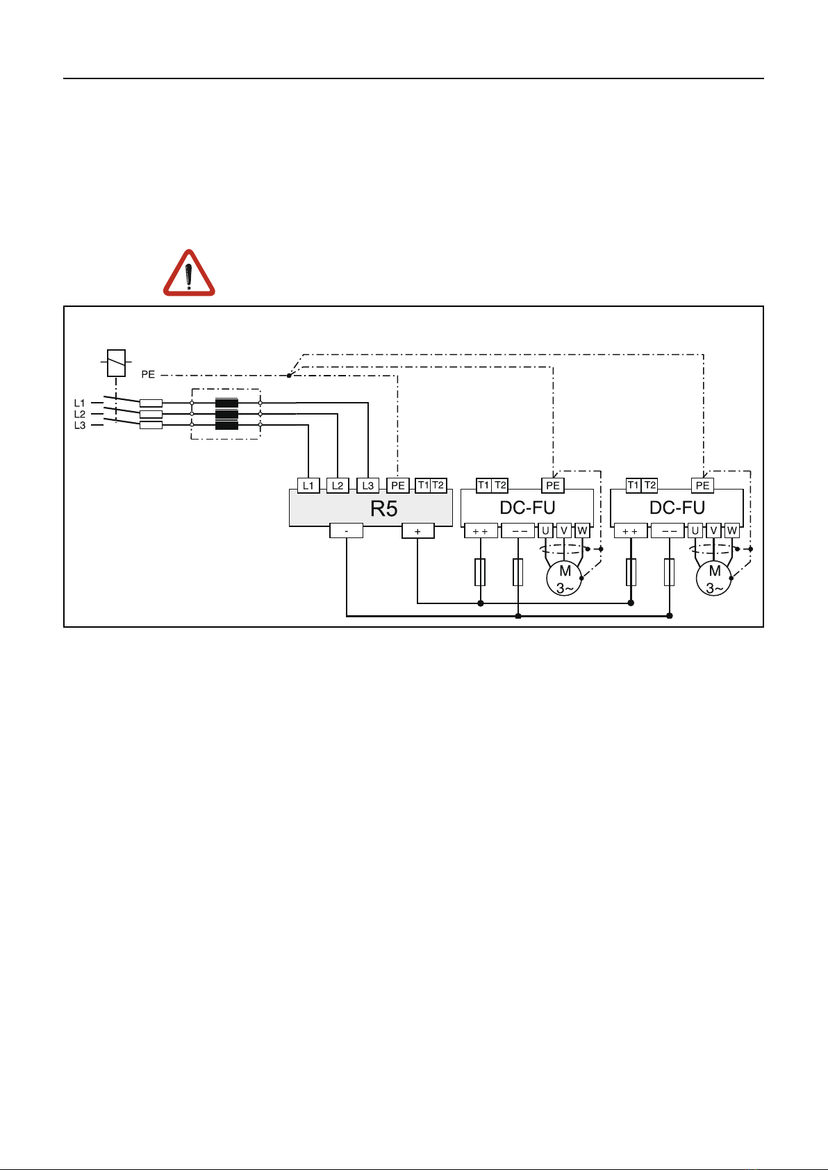
The units are not short-circuit proof without corresponding dimensioned fuses.The max.
loadable DC link capacity is 100000 µF. Exceeding the capacity triggers the error "charge
time out" (E.cto). Do not charge the DC link during the load cycle.
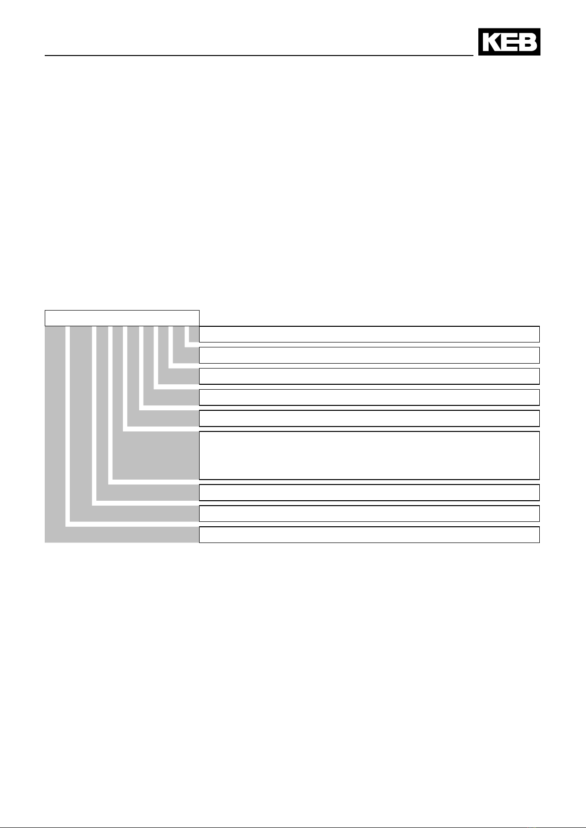
Rectiersize 19 23 25 27 28 29
Housing size R R R U U U
Chargeable inverter power 1) [kW] 30 75 110 160 200 250
DC nominal output current [ADC]90 180 270 380 470 610
Max. short time current 2) [AAV]135 270 405 570 705 915
OL current [ADC]153 306 459 646 799 1037
Input current 3) [ARMS]79,8 147,5 221 312 386 500
Mains voltage [V ACRMS]305…504 +/- 0%
Phases 3
Output voltage [V DC] 430…713
Maximal permissible mains fuse [A] 100 200 350 500 710 710
I2t mains fuse [A2s] <19.100 <128.000 <236.000 <423.000 <1.062.000 <1.062.000
Supply line cross section (min) [mm2]35 95 150 2x150 2x185 2x185
Supply line cross section (max) [mm2]95 150 150 2x185 2x185 2x185
DC line cross section (min) [mm2]50 120 150 2x150 2x150 4x95
DC line cross section (max) [mm2] 95 150 150 4x185 4x185 4x185
Storage temperature [°C] -25…70
Operation temperature [°C] -10…45
Climatic category (EN 60721-3-3) 3K3
Protective system IP20 IP00
Power loss at nominal operating [W] ca. 220 ca. 400 ca. 600 ca. 1050 ca.1200 ca.1600
Max. heat sink temperature [°C] 90
Internal braking option Option
Max. braking current [A] 133 133 200 250 250 250
Min. braking resistor [Ohm] 6 6 4 3,2 3,2 3,2
Typ. braking resistor [Ohm] 15 6,7 4,3 4,3 3,2 3,2
Line cross section braking resistor [mm2]35…95 16…185
Weight [kg] 28 49 54 56

GB - 9
Installation
C
B
H
Ø F
A
G
3.1.2 Installation Instructions
The COMBIVERT R5 is provided for vertical installation. The following minimum
distances must be observed:
30
150
100
3. Installation
3.1 Unit Installation
3.1.1 Dimensions
Housing A B C F G H
R 340 545 355 10 300 515
U 340 800 408 11 300 774

GB - 10
Installation
3.2 Connection of the Power Unit
3.2.1 Mains Connection of the Supply Unit
• absolutely use a line reactor
• in case of interconnected operation with several supply units consider
information sheet 00.R5.0DM-I000 !
Switching at the input without waiting of an under-potential error (E.UP) causes
high wear of the switching contacts. Fuses and overcurrent protection units can
release furthermore. See publication ENG 000 0001.
Connection of the supply unit

GB - 11
3.2.2 Terminal strips of the power circuit
All terminal strips following the requirements of the EN 60947-7-1 (IEC 60947-
7-1)
Connection terminals
Terminal in acc. with table 3.2.2.1
-PB PA+ + -
PE PE
Name Function No.
L1, L2, L3 3-phase mains connection
4
PA,PB Connection for braking resistor
+, – DC link output
L1 L2 L3
PE Connection for shielding /earthing
Terminal in acc. with table 3.2.2.1
+
T1 T2
PB PA
-
Name Function No.
L1, L2, L3 3-phase mains connection
1
+, - DC link output
PA,PB Connection for braking resistor 2
L2 L3
L1
T1, T2 Connection for temperature sensor 3
Connection for shielding /earthing 4
Table3.2.2.1 Permissible cable cross-sections and tightening torques of the terminals
No.
permissible cross-section exible with wire-end ferrule Max. tightening torque
mm² AWG/MCM Nm lb inch
min max min max
1 50 150 6 AWG 0 MCM 25…30 220
2 35 95 4 AWG6 000 MCM 15…20 150
3 0.2 4 24 AWG 10 AWG 0.6 5.3
4 10 mm stay bolt for ring thimble 25 220
Installation

GB - 12
It is absolutely necessary to monitor the braking resistance temperature switch
to record a braking resistance overheat. The overheat may be caused by:
• incorrect dimensioning of the braking resistance
• the input voltage being too high
The current of the brake transistor is monitored additionally. The input thyristors
are switched off in case of a short circuit.
Braking resistors can develop a very high surface temperatures, therefore install
as safe-to-touch as possible!
3.2.3 Connection of the Braking Resistor
Connection of a braking resistor
As standard the evaluation at
terminals T1 and T2 is switched off
and must be activated if necessary
(application mode Pn.12=“7“).
Installation

GB - 13
An external temperature sensor/switch can be connected to the terminals T1,
t2 . The supply unit switches off with the error message E.OH during tripping.
As standard the evaluation at terminals T1 and T2 is switched off and must be
activated if necessary (application mode Pn.12=“7“).
3.2.4 Connection of a Temperature Detection
other PTC
Temperature sensor (PTC)
Tripping resistance 1650 Ω…4 kΩ
Reset resistance 750 Ω…1650 Ω
(acc. VDE 0660 Teil 302)
Installation
other
3.3 Instructions of an EMC-conform Installation
• To avoid coupled-in noise, separate
a) Line-supply cables,
b) Motor lines of frequency inverters/servo power controller,
c) Lay control and data lines (low-voltage level <48 V), with a distance of
at least 15 cm.
• In order to maintain low-resistance high frequency connections, earthing and
shielding, as well as other metallic connections (e.g. mounting plate,
installed units ) must be in metal-to-metal contact with the mounting plate,
over as large an area as possible. Use earthing and equipotential lines with
a section as large as possible (min. 10mm2) or use thick earthing strips.
• If external interference suppression lters are used, then these must be
installed as close as possible to (<30cm from) the interference source and
in metal-to-metal contact with the mounting plate, over as large an area as
possible.
• Always equip inductive control elements (contactors, relays etc.) with
suppressors such as varistors, RC-elements or damping diodes.
• All connections must be kept as short as possible and as close as possible
to the earth, as free oating lines work as active and passive aerials.
• Keep connection cables straight (do not bundle). Install a non-assigned wire
on both sides of the protective conductor.
• The ow and return circuit must be twisted when the lines are not shielded,
in order to dampen common-mode noise.
• As a general principle use metal cable glands with shield connection.

GB - 14
Installation and connection
4. Installation and connection
4.1 Control Card Version C
4.1.1 AssignmentoftheTerminalStripX2A
X2A
PIN Function Name Explanation
1...4 without function - - - -
5 Analog output 1: ANOUT1 Analog output of the DC output current
0…10 VDC ^ 0…200 %
Voltage range:
0…±10 V
Ri: 100 Ω
Resolution: ±10Bit
6 Analog output 2: ANOUT2 Analog output of the DC voltage
0…10 VDC ^ 0…1000 VDC
7 without function - - - -
8 Analog mass COM Mass for analog in- and outputs
9 Analog mass COM
10 without function - - I1 -
Ri: 2,1 kΩ
Scan time: 4 ms
11 without function - - I2 -
12 without function - - I3 -
13 without function - - I4 -
14 Slave input I5 only interconnected operation
00.R5.0DM-I000
15 without function - - I6 -
16 Start ST Thyristors switched through
Error reset during opening
17 Reset RST Reset; only possible in fault condition
18 Transistor output 1 O1 „Run“; is set, if the thyristors are switched trough
19 Transistor output 2 O2 „Error" is set, if the unit switched off on error
20 24 V-output Uout Power supply for digital inputs Imax: 100 mA
21 without function - - - -
22 Digital ground 0V Reference potential for digital in-/outputs
23 Digital ground 0V
24 Relay 1 / NO contact RLA
Relay output
Ready for operation signal
max. 30 V DC
0.01…1 A
25 Relay 1 / NC contact RLB
26 Relay 1 / switching
contact
RLC
27 Relay 2 / NO contact FLA
Relay output
phase error warning
28 Relay 2 / NC contact FLB
29 Relay 2 / switching
contact
FLC
123456789 10 11 12 13 14 15 16 17 18 19 20 21 22 23 24 25 26 27 28 29

GB - 15
4.1.2 Connection of the control
In order to avoid malfunctions caused by interference voltage supply at the
control inputs, the following instructions must be observed:
• Use shielded/drilled cables
• Lay shield on one side of the inverter onto earth potential
• Lay power and control cable separately (about 10…20 cm distance); lay
cables in a right angle
EMC
max. 30 V DC
0,01…1A
max. 30 V DC
0.01…1A
max. 50 mA DC
for both outputs
Analog output
0…10 V DC / 5 mA
Installation and connection

GB - 16
Operation of the Unit
5. Operation of the Unit
An operator is necessary as accessories for local or external (Option: cable 00.F5.0C0-1xxx) programming
of the frequency inverter KEB COMBIVERT. In order to avoid malfunctions the frequency inverter must be
brought into status nOP before plug-on/remove of the operator (open control release). During starting of the
frequency inverter it always starts with the last stored values/factory setting.
5.1 Operator
Digital operator with operation and display: Part No. 00.F5.060-1000
Interface operator additionally with serial interface: Part No. 00.F5.060-2000
START
FUNC.
SPEED
ENTER
F/R
STOP
COMBIVERT
X6C X6D
X6B
Only use the operator interface for the serial data transfer to RS232/485.The
direct connection, PC to the inverter is only valid with a special cable (HSP5
PartNo. 00.F5.0C0-0001), otherwise, it would lead to the destruction of the
PC-interface!
54321
9876
Double function
keyboard
Status-/Error display
Normal "LED on"
Error "LED blinks"
Interface check
BUS-operation "LED on"
(only 00.F5.060-2000)
5-digit LED display
RS232/RS485
(only 00.F5.060-2000)
SUB-D 9 pole male
Housing (PE)
PC F5-Operator
RS232-cable 3m
PC / Operator
Part No. 00.58.025-001D
HSP5 diagnostic interface
(only 00.F5.060-2000)
PIN RS485 Signal Meaning
1 - - reserved
2 - TxD transmission signal RS232
3 - RxD receive signal RS232
4 A‘ RxD-A receive signal A RS485
5 B‘ RxD-B receive signal B RS485
6 - VP voltage supply plus +5 V (Imax=10 mA)
7 C/C‘ DGND data reference potential
8 A TxD-A transmission signal A RS485
9 B TxD-B transmission signal B RS485
SUB-D 9 pole female

GB - 17
5.1.1 keyboard
When switching on KEB COMBIVERT R5 the value of parameter CP.1 is
displayed. (change-over of the keyboard function see Drivemode)
Principally during a change, parameter values are immediately accepted and
stored non-volatile. However, with some parameters it is not useful that the
adjusted value is accepted immediately. When this type of parameter is changed
a point appears behind the last digit.
If a malfunction occurs during operation, the actual display is overwritten by the
alarm message. The alarm message in the display is reset by ENTER.
With ENTER only the error message in the display is reset. In order to reset the
error itself, the cause must be removed or a power-on reset must be made. In
the status display (CP. 1) the error will still be shown.
Operation of the Unit
FUNC.
SPEED
The function key is
used to change between
parameter value and
parameter number.
START
STOP
With UP and DOWN the
value of the parameter
number is increased/
decreased with
changeable parameters.
ENTER
F/R
The adjusted value
is accepted and non-
volatile stored with
ENTER.
Error
ENTER
F/R
START
STOP

GB - 18
Operation of the Unit
5.2 Parameter summary
The CP parameters are one of the parameter selection dened by KEB. You need an application manual in
order to get access to the entire parameters.
FUNC
ENTER
UP
Password
Password
FUNC
ENTER
UP
Blocking the CP-Parameter
Releasing the CP-Parameter
5.3 Password input
Ex works the frequency inverter is supplied without password protection, this
means that all changeable parameters can be adjusted. After parameterizing
the inverter can be secured against unauthorized access. The adjusted mode
is stored.
Display Parameter Setting range Resolution Fact. setting
CP. 0 Password input 0…9999 1 –
CP. 1 Status display – – –
CP. 2 AC input current – 0.1A –
CP. 3 DC output current – 0.1A –
CP. 4 DC - output current / peak value – 1 % –
CP. 5 current DC - utilization – 1V –
CP. 6 current DC - voltage – 1V –
CP. 7 DC output voltage – 1V –
CP.8 DC - output voltage / peak value – 1V –
CP.9 Heat sink temperature – 1 °C –
CP.10 Charging time factor 100…500 % 1 % 100 %
CP.11 Analog output 1 gain -20.00…20.00 1 1.00
CP.12 Analog output 2 gain -20.00…20.00 0.01 1.00
CP.13 AC-Phase current L1 – 0.1A –
CP.14 AC-Phase current L2 – 0.1A –
CP.15 AC-Phase current L3 – 0.1A –

GB - 19
Operation of the Unit
5.4 Parameter Description
The following parameters serve for the functional monitoring during operation.
CP. 1
Inverter state
The status display indicates the actual operating condition of the inverter.
Possible displays and their meaning:
noP "no Operation" Starting terminal not bridged, thyristors blocked,
output voltage = 0 V
run "run" supply unit ready for operation; Thyristors connected
charG "charge" DC output voltage is loaded on actual DC voltage
GFt "Ground Fault test" is displayed during power-on test.
E.GF1 Earth fault during power-on test
E.GF2 Earth fault during operation
E.cto "Error charge time out" DC output voltage could not be loaded
within the adjusted charging time.
E.rEco "Error rectier output" Difference between DC output voltage and
actual DC voltage during the operation higher than 200 V.
E.UPh "Error Phase failure" detects an error in one input phase (see
6.6.5). The utilization of L1, L2 and L3 is compared all 4ms with
the average value of the effective input currents (CP. 2) If after
triple scanning (12 ms) a difference of >15 % of one phase to CP.2
is detected, then
• a prewarning is released and switched off after 60s, if the
difference is < 50%.
• immedeiately switched off, if the difference is ≥ 50 %.
CP. 2
ACcurrent
Display of the average value of the effective input currents of phase L1...L3
in ampere.
CP. 3
DC current
Display of the actual DC output current in ampere.
CP. 4
DC current
peak value
This display enables a detection of short-term current peaks, as the highest
value that occurred is stored.
The peak value can be reset with UP or Down when the unit is switched on.
Switching off the unit deletes the peak value.
CP. 5
Actual
DC gain
Display of the actual utilization of the supply unit in percent. 100 %
correspond to the rated current.
CP. 6
Actual
DC voltage
Display of the current DC voltage in volt. The value is measured in the
charge circuit. The value serves as comparison value to the DC output
voltage.
CP. 7
DC-
Output voltage
Display of the current DC output voltage in volt. The value is measured at
the output terminals of the supply unit.

GB - 20
Operation of the Unit
CP. 8
DC - output voltage /
peak value
This display enables a detection of short-term voltage peaks, as the highest
value that occurred is stored.
The peak value can be reset with UP or Down when the unit is switched on.
Switching off the unit deletes the peak value.
CP. 9
Heat sink temperature
Display of the actual heat sink temperature in °C. First a prewarning is given
out if the heat sink temperature is too high, so a controlled deceleration of
the unit is possible. The thyristors are blocked when reaching the max. heat
sink temperature of 90 °C, if there is no reaction to the pre-warning.
CP.10
Charging time factor
The charge time is dependent on the connected total capacity. The preset
value of 100% is 16 s. If the charge time should be exceeded in case of
very large capacities, the charge time can be extended up to 500 % with the
charge time factor.
CP.11
Analogoutput1gain
At a gain of "1" the analog output 1 outputs a signal in a range of 0...10 VDC
= 0...150 % IDC which corresponds to the DC-output current. The gain can
be adjusted with CP.11 in a range of ±20,00. The analog output can be
adapted thereby to individual requirements.
CP.12
Analogoutput2gain
At a gain of "1,00" the analog output 2 outputs a signal in a range of
0...10 VDC = 0...800 V UDC which corresponds to the DC- output current.
The gain can be adjusted with CP.11 in a range of ±20,00. The analog
output can be adapted thereby to individual requirements.
CP.13
AC-PhasecurrentL1
CP.13 displays the rms value of the input current of phase L1 in ampere.
CP.14
AC-PhasecurrentL2
CP.14 displays the rms value of the input current of phase L2 in ampere.
CP.15
ACcurrentL3
CP.15 displays the rms value of the input current of phase L3 in ampere.
Table of contents
Other KEBCO Power Supply manuals

KEBCO
KEBCO combivert R6-S User manual

KEBCO
KEBCO combivert R6-S User manual

KEBCO
KEBCO COMBIVERT F5 User manual

KEBCO
KEBCO Combivert R6 User manual

KEBCO
KEBCO Combivert R6 User manual

KEBCO
KEBCO combivert R6-S User manual

KEBCO
KEBCO Combivert R6 User manual

KEBCO
KEBCO Combivert R6 User manual

KEBCO
KEBCO combivert R6-S User manual