LifeSafety Power FlexPower User manual

LifeSafety Power, Inc. | PH 888.577.2898 | TechSupport@LifeSafetyPower.com
P03-40 Rev A15
DC Power System Installation Manual
FlexPower

FlexPower DC Power System Installation Manual
ii iii
Table of Contents
Notes and Warnings ......................................iii
Symbol Definitions ............................................................ iii
Warnings.................................................................... iii
Regulatory Information ......................................................... iii
Conventions Used Within this Manual.............................................. iii
Power Supply Quick Start ..................................iv
Section 1 – Installation and Operation .........................1
1.1 Mounting .................................................................1
1.2 Jumper / LED / Connector Descriptions ..........................................3
1.3 FAI Input Usage ............................................................6
1.4 Typical Installation & Wire Routing .............................................7
1.5 Power-Up and Basic System Verification Checklist .................................8
Section 2 – Troubleshooting and Maintenance ....................9
2.1 Troubleshooting Table .......................................................9
2.1 Troubleshooting Table (continued) .............................................10
2.2 Maintenance Instructions ....................................................10
Section 3 – Specifications ................................. 11
3.1 Electrical Specifications .....................................................11
3.2 Temperature Specifications ..................................................13
3.3 Mechanical Specifications ...................................................13
3.4 Replacement Parts .........................................................14
Appendix 1 – Tamper Switch Wiring .......................... 15
Appendix 2 – User Certificate............................... 16
Appendix 3 – UL Compliance Verification Sheet .................. 17

FlexPower DC Power System Installation Manual
ii iii
Symbol Definitions
The following symbols are used throughout this manual:
h This symbol is intended to alert the installer of shock
hazards within the enclosure. Service should only be
performed by qualified service personnel
iThis symbol is intended to alert the installer of important
information intended to help the installer avoid personal
injury or property damage
Warnings
h Installation and service should be performed only by
qualified service personnel and should conform to all
local codes
h To reduce the risk of electric shock or fire, do not
expose this equipment to rain or moisture
i This equipment shall be installed in a manner which
prevents unintentional operation by employees,
cleaning personnel, or others working in the prem-
ises, by falling objects, customers, building vibration,
or similar causes
i This equipment is not intended for use within the pa-
tient care areas of a Health Care Facility
h Replace fuses only with the same type and rating as
indicated in the specifications section of this manual.
i To prevent impaired operation, ensure that all wiring
is routed and secured to prevent accidental open or
short circuit conditions
i The system and any batteries (if used) should be
tested at least once per year to ensure proper opera-
tion
i Batteries (if used) should be maintained at an am-
bient temperature of between 32 and 120 degrees
Fahrenheit (0-49 Celsius) or premature loss of bat-
tery power could occur
Regulatory Information
The equipment discussed within this manual has been test-
ed to the following standards:
• UL294, UL603, UL1076
• ULC S318, ULC S319
• CSA C22.2 #107.1, CSA C22.2 #205
FCC Information
Note: This equipment has been tested and found to comply
with the limits for a Class A digital device, pursuant to Part
15 of the FCC Rules. These limits are designed to provide
reasonable protection against harmful interference when
the equipment is operated in a commercial environment.
This equipment generates, uses, and can radiate radio fre-
quency energy and, if not installed and used in accordance
with the instruction manual, may cause harmful interfer-
ence to radio communications. Operation of this equipment
in a residential area is likely to cause harmful interference in
which case the user will be required to correct the interfer-
ence at his own expense.
Conventions Used Within this Manual
Positional information (e.g. top, bottom, up, down, left,
right, etc.) is referenced with the board or enclosure in the
orientation shown in the illustrations in this manual.
Notes and Warnings

FlexPower DC Power System Installation Manual
iv 1
Installation and Operation
This section gives a quick visual guide of installation connections and settings for installers already familiar with the Flex-
Power line of power supplies. For full information, please read this entire manual before installing.
+ –+ –+ –+ –
AC Input
Battery
Presence Jumper
Battery
Presence Jumper
Cut for
230VAC input
FAI Input - section 1.2 #10 & section 1.3
Fault Contacts/AC - section 1.2 #8
Fault Contacts/System - section 1.2 #8
Flex IO Connector - section 1.2 #6
Earth Ground Jumper - section 1.2 #5
section 1.2 #3section 1.2 #3
section 1.2 #1section 1.2 #1
QUICK INSTAL - SECTION FINDER
FAI
Flex
E GRND SYS AC
section 1.2, #9
Main Output
section 1.2 #17
12/24 V Selection
section 1.2 #20
FAI Controlled Output
section 1.2 #16
Battery Connection
section 1.2 #13
FlexConnect
Accessory Power
section 1.2 #11
Models ending in "/E"
are factory preset for 230VAC
with JP1 jumper already cut
Power Supply Quick Start
Figure 2

FlexPower DC Power System Installation Manual
iv 1
Installation and Operation
Mounting an Enclosure
Use the following procedure when mounting a wall-mount enclosure
(figure 1).
1. (Optional) Remove the enclosure’s cover.
2. Locate the top keyhole mounting holes in the back of the enclosure.
3. Mark and pre-drill the locations for the keyholes in the mount-
ing surface.
4. Partially install two fasteners appropriate for the surface on
which the enclosure is being installed. Leave the heads of the
fasteners approximately ¼" out from the surface. Minimum
fastener size should be #10 or larger.
5. Hang the enclosure on the two fasteners and mark the loca-
tions of the remaining mounting holes.
6. Remove the enclosure and pre-drill the locations for the re-
maining mounting holes.
7. Re-hang the enclosure on the top mounting fasteners, start
the remaining fasteners and tighten all fasteners.
8. Reinstall the enclosure’s cover, if removed in step 1.
iIt is the installer’s responsibility to determine the ap-
propriate fastening system for use with the surface the
enclosure is being mounted to.
iFor UL1076 applications, after installation is complete, the
installer must install the two supplied 1" long screws to the
edge of the enclosure's cover for additional security.
Mounting an FPO PS Board to an Enclosure
Use the following procedure when mounting an FPO power sup-
ply to a LifeSafety Power enclosure (figure 2).
1. Locate the appropriate mounting holes in the enclosure and
snap the four or six standoffs provided into the holes.
2. Align the board mounting holes (mounting hole locations are
indicated in the drawing above) with the standoffs and snap the
board onto the standoffs. Be sure the board is properly oriented
before snapping the board onto the standoffs (Figure 3).
3. When two FPO/FPV boards are installed, the larger shall be
located on top (figure 4).
Mounting a Sub Assembly to an Enclosure
Third Party sub assemblies will be mounted in one of three methods
based on the supplied mounting hardware (figure 5).
1.1 Mounting
The following pages cover the installation, setup, and basic operation of the FPO series power supplies.
Section 1 – Installation and Operation
FPO/FPV
smaller
FPO/FPV
larger
Figure 1 Figure 2 Figure 3
Figure 5
Figure 4
Screw
Female to female Stando
Screw
Male to female Stando
Screw mounting

FlexPower DC Power System Installation Manual
2 3
Installation and Operation
FAI INPUTFAI INPUTSYS FLTSYS FLT AC FLTAC FLT BRBR
DC1DC1
V+V+ V-V-
DC2DC2
DataLinkDataLink
+ DC2 –+ DC2 – + DC1 –+ DC1 –
AC Input
Flex IO
Earth
GND DET
Battery
Detect
Battery
Detect
120/230VAC
Cut for 230VCut for 230V
DC2 NCDC2 NC
DC2 NODC2 NO
DC1
DC2
AC ON
REV BAT
GND FLT
AC FLT
FAI
SYS FLT
12V
24V
BB+
BB–
2
1
Observe battery polarity
or damage may result
Observe battery polarity
or damage may result i
FPO150 / 250
For UL compliance, the AC fault contact
must be monitored by a Listed control panel
21
FAI INPUTFAI INPUTSYS FLTSYS FLT AC FLTAC FLT
12V
24V
Observe battery polarity
or damage may result
Observe battery polarity
or damage may result
i
+ DC2 –+ DC2 – + DC1 –+ DC1 –
AC Input
Flex IO
120/230VAC
Cut for 230VCut for 230V
DC2 NCDC2 NC
DC2 NODC2 NO
FPO75
AC ON DC2
DC1
REV BAT
GND FLT
AC FLT
FAI
SYS FLT
DataLinkDataLink
BB+
BB–
BRBR
DC1DC1
DC2DC2
For UL compliance, the AC fault contact
must be monitored by a Listed control panel
Earth
GND DET
21
Battery
Detect
Battery
Detect
2
1

FlexPower DC Power System Installation Manual
2 3
Installation and Operation
1.2 Jumper / LED / Connector Descriptions
1AC Input Voltage Selection (JP1)
This jumper configures the FPO for the AC input voltage to be used.
• Leave jumper INTACT for 120V input
• CUT and remove jumper for 230V input
I Models ending in "/E" are preset for 230VAC already
IFailure to cut this jumper when using the FPO with a
230VAC input will result in damage to the system and void the
warranty.
2FAI and Fault LED Status Indicators
FAI (D22) – Red
This LED lights when a valid FAI signal is received on the
FAI input terminals.
GND FLT (D42) – Yellow
This LED lights when an impedance is detected between
earth ground and any voltage output or DC common. A
Ground Fault will also light the System Fault LED.
AC FLT (D43) – Yellow
This LED lights when the AC input voltage is low or missing.
SYS FLT (D33) – Yellow
This LED lights when a system trouble is detected by the
FPO. Trouble conditions indicated by the SYS FLT LED
include:
• Missing Battery (If BAT DET jumper is ON)
• Earth Ground Fault (If EARTH GND DET jumper is ON)
• Battery voltage out of range
• DC output voltage out of range
• Ruptured fuse
• Accessory Board Fault
• Internal Fault
3AC Input (J9)
J9 accepts the provided three-wire connector harness for
connection to the AC Line. Cut jumper JP1 if powering the FPO
with a 230VAC input. Connections are by wire nut as follows:
120VAC 230VAC
White – Neutral White – Phase 2
Green – Earth Ground Green – Earth Ground
Black – Hot Black – Phase 1
IModels ending in "/E" have the JP1 jumper pre-cut for
230VAC operation only (see #1 above).
4AC ON (D34) – Green
This LED lights when any AC voltage is present on the AC in-
put. It does not indicate that the voltage is sufficient for proper
operation of the FPO power supply. See the yellow AC FLT LED
for AC voltage out of range indication.
HAlways confirm the absence of AC power with a meter
before servicing to prevent electric shock.
5Earth Ground Fault Detection (JP2)
The EARTH GND DET jumper enables or disables Earth Ground
(EG) fault detection as follows:
• Position 1 (jumper ON) Enable EG Fault Detection
• Position 2 (jumper OFF) Disable EG Fault Detection
Note: Postion 2 is the factory default position
Earth Ground fault detection detects continuity between earth
ground and any voltage output or DC common on the system.
IOnly one component of an entire system should be en-
abled for earth ground detection to avoid conflicts.
6FlexIO Connection
This connector supplies the fault and FAI status between the
FPO power supply and any accessory boards in the system.
The appropriate cable is supplied with the accessory boards.
For more information, see the instruction manual for any ac-
cessory boards used in the system.
7DataLink Connection
This is the connector for the DataLink connection. It allows op-
tional programming and monitoring of the FPO power supply
via computer or through an optional NetLink network module.
DataLink cables and the PowerCom software package are
available separately from LifeSafety Power for accessing these
features.
See the instructions for the Netlink module or PowerCom
software for more information.
8Fault Output Connections (TB3)
These terminals provide the System Fault and AC Fault contact
outputs. The terminals are removable and are labeled on the
PC board in the non-powered (fault) state. For UL1076 compli-
ance, a tamper switch must be wired in series with the Sys
Fault contact output. See Appendix 1 for tamper switch wiring
information. These terminals accept AWG14 – AWG22 wire.
Fault conditions reported include:
AC FLT
• Low AC
• Missing AC
• Internal Fault
For UL compliance, the AC fault contact must be monitored
by a Listed control panel
SYS FLT
• Missing Battery (If BAT DET jumper is ON)
• Earth Ground Fault (If EARTH GND DET jumper is ON)
• Battery voltage out of range
• DC output voltage out of range
• Ruptured fuse (DC1)
• Accessory Board Fault
• Internal Fault

FlexPower DC Power System Installation Manual
4 5
Installation and Operation
FAI INPUTFAI INPUTSYS FLTSYS FLT AC FLTAC FLT BRBR
DC1DC1
V+V+ V-V-
DC2DC2
DataLinkDataLink
+ DC2 –+ DC2 – + DC1 –+ DC1 –
AC Input
Flex IO
Earth
GND DET
Battery
Detect
Battery
Detect
120/230VAC
Cut for 230VCut for 230V
DC2 NCDC2 NC
DC2 NODC2 NO
DC1
DC2
AC ON
REV BAT
GND FLT
AC FLT
FAI
SYS FLT
12V
24V
BB+
BB–
2
1
Observe battery polarity
or damage may result
Observe battery polarity
or damage may result i
FPO150 / 250
For UL compliance, the AC fault contact
must be monitored by a Listed control panel
21
FAI INPUTFAI INPUTSYS FLTSYS FLT AC FLTAC FLT
12V
24V
Observe battery polarity
or damage may result
Observe battery polarity
or damage may result
i
+ DC2 –+ DC2 – + DC1 –+ DC1 –
AC Input
Flex IO
120/230VAC
Cut for 230VCut for 230V
DC2 NCDC2 NC
DC2 NODC2 NO
FPO75
AC ON DC2
DC1
REV BAT
GND FLT
AC FLT
FAI
SYS FLT
DataLinkDataLink
BB+
BB–
BRBR
DC1DC1
DC2DC2
For UL compliance, the AC fault contact
must be monitored by a Listed control panel
Earth
GND DET
21
Battery
Detect
Battery
Detect
2
1

FlexPower DC Power System Installation Manual
4 5
Installation and Operation
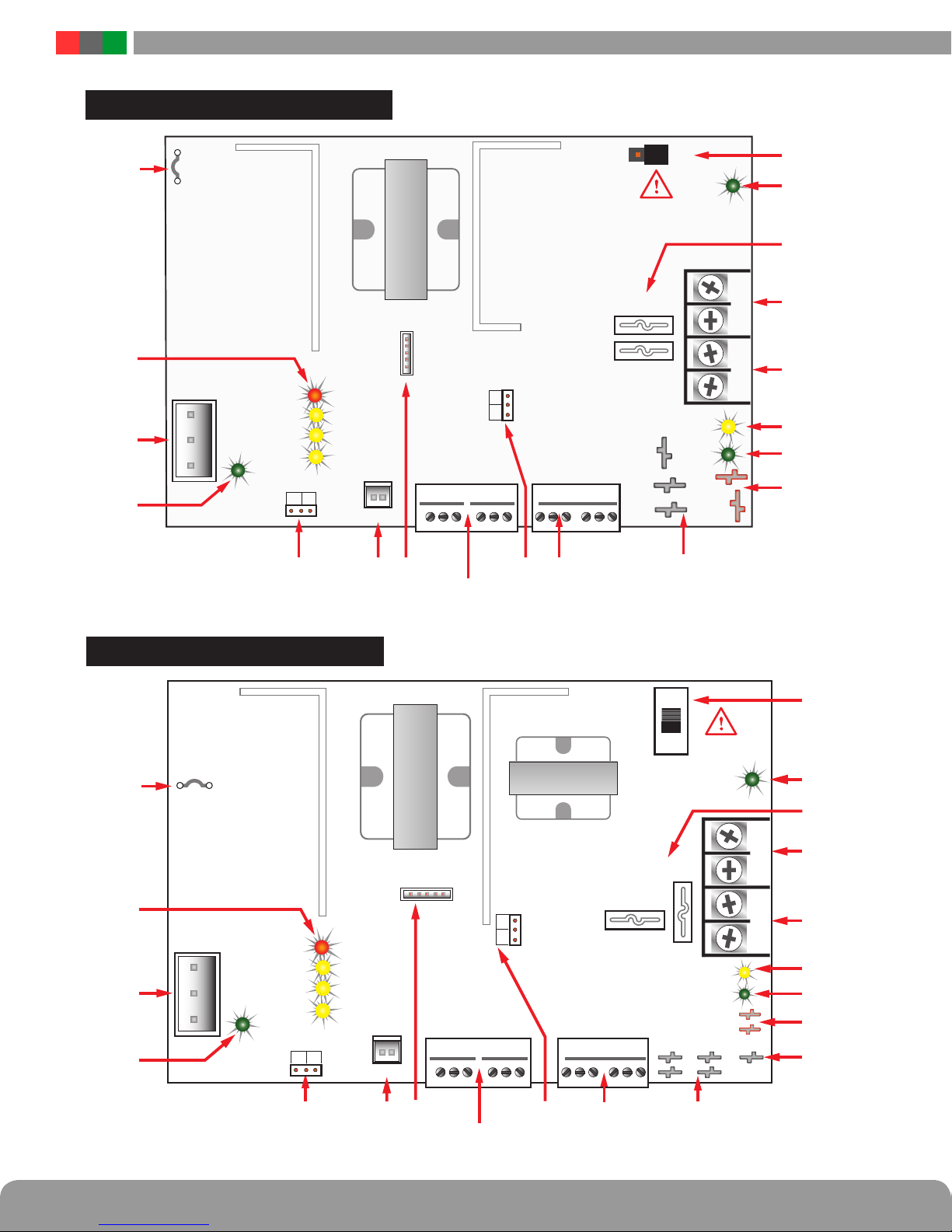
9Battery Presence Detection (JP3) The BAT DET jumper en-
ables or disables Battery Presence (BP) fault detection as follows:
• Position 1 (jumper ON) Enable EG Fault Detection
• Position 2 (jumper OFF) Disable EG Fault Detection
IEnabled (Postion 1) is the factory default position which
will cause a fault too occur if a battery is not connected.
Battery Presence fault detection indicates a fault when the backup
battery is disconnected from the FPO power supply. If no backup
battery is being used, this jumper should be removed.
bk FAI Input Connections (TB2) These terminals accept the
optional FAI / Access Control input for controlling the DC2 output
and any FAI capable accessory boards connected to the FPO power
supply. The terminals are removable and are labeled on the PC
board. These terminals accept AWG14 – AWG22 wire. See Section
1.3. Connections are as follows:
• I+ & I– TerminalsThese terminals are the input terminals for the
FAI Input. The FAI input is activated when a voltage between 9
and 30 volts is applied across these terminals in the correct polar-
ity. See Section 1.3 - FAI Input Usage for more information.
• V+ & V– TerminalsThese terminals are a low-current auxiliary
voltage output and are typically used with a dry contact or open
collector for activating the FAI Input's I+ and I- terminals.
• L TerminalsLatch Reset contact input. If a latching FAI Input is
desired, a normally closed contact is placed across these termi-
nals. When the FAI Input is activated, it will latch in the activated
state until this contact is momentarily opened. If the latching
feature is not desired, leave these terminals open.
bl FlexConnect Power Connections Faston connectors for
the power connection to any accessory boards to be connected.
Pre-terminated power leads are provided with the accessory
boards. For more information, see the instruction manual for any
accessory boards used in the system. Connections are as follows:
• DC1This faston provides a constant voltage output for
connection to the accessory boards.
• BRThe DC Common (DC Ground) for the FPO power supply.
• DC2This faston provides an FAI controlled output that
operates in conjunction with the DC2 output terminals. This
connection is typically only used in single voltage systems
with D8 accessory boards. See the sections on the FAI Input
and DC2 Output Configuration for more information.
bm
NetLink Power Connection (V+ & V–) Faston connec-
tors for powering a NetLink network module. Do not power the
NetLink module from the DC1 or DC2 buss. See the NetLink
module manual for more information.
bn Battery Connection (BAT+ & BAT–) Faston connectors
for connection of the backup battery set. Pre-terminated
battery leads are provided. See the Specifications section
for the maximum battery size. If no battery set is to be
used, ensure the BAT DET jumper is off to prevent a fault
condition from being annunciated.
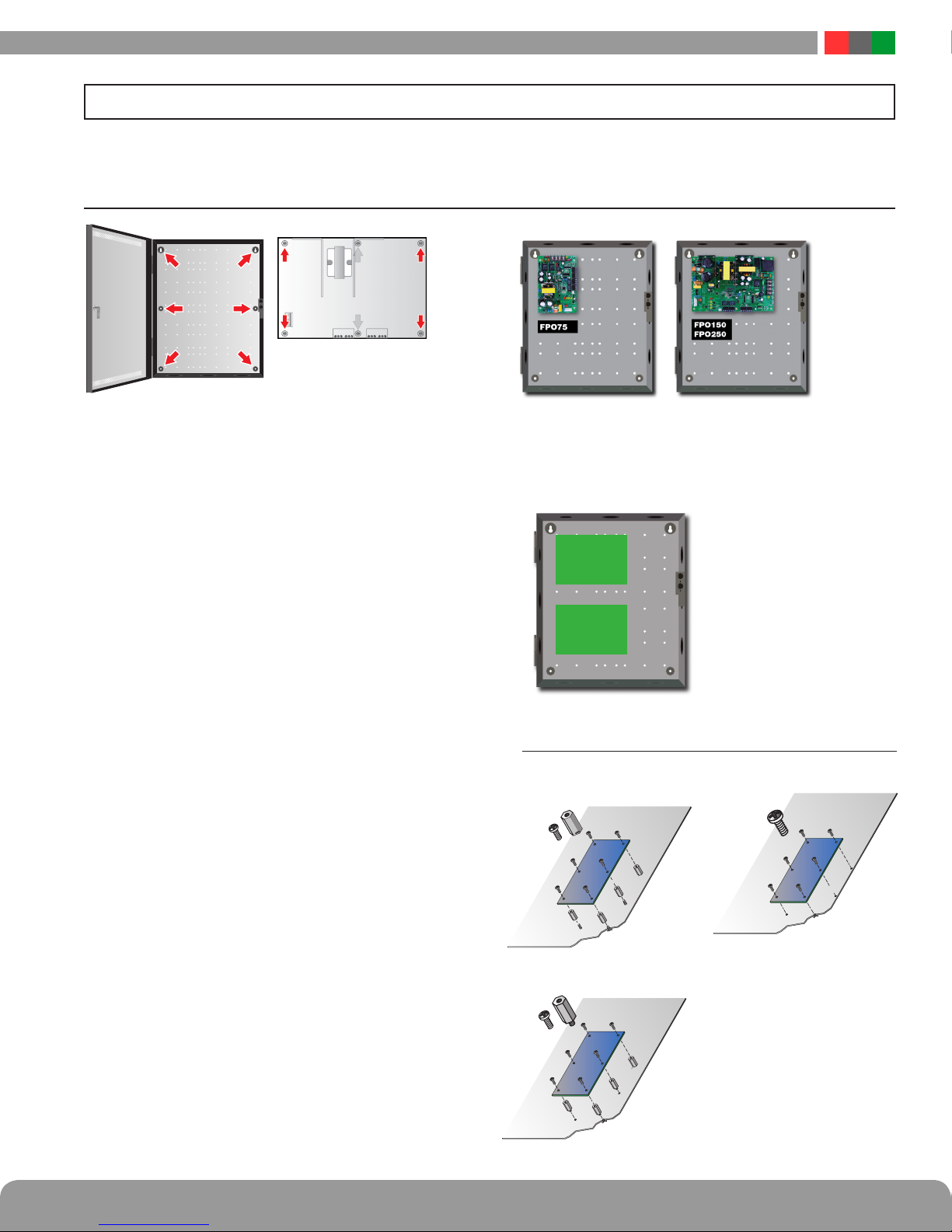
HNote that FPO75 PCB and FPO150-250 PCB's have different
battery connection layouts.
HA FPO set for a 12V output requires a 12V battery set. A FPO
supply set for a 24V output must use a 24V battery set (two
12V batteries in series).
HObserve polarity or damage to the system will occur.
HIt is the installer’s responsibility to determine the proper bat-
tery size for the installation. See the Specifications section for
standby current requirements.
bo DC2 (D5) – Green
This LED lights when voltage is available on the DC2 output
terminals. This LED will extinguish if the output is disabled via
the FAI input.
bp REV BAT (D20) – Yellow
This LED lights if the backup battery set is connected in the
reverse polarity. The lighting of this LED will also be accompa-
nied by the rupture of the battery fuse (F4) and the lighting of
the SYS FLT LED.
bq DC2 Output (TB1) The DC2 output may optionally be con-
trolled by the FAI input. The full current of the FPO is available on
these terminals. If not using the FAI input, the DC2 fuse should be
inserted into the NC fuseholder to allow the DC2 output to provide
continuous power. See the sections on the FAI Input and DC2
Output Configuration for more information. These terminals accept
AWG12 – AWG18 wire.
IWhen powering magnetic loads such as maglocks, door
strikes, solenoids, etc, each of these loads must have a reverse
protection diode either built-in or external to the device.
br DC1 Output (TB1) The main DC output of the FPO power
supply. The full current of the FPO is available on these terminals at
all times and is unaffected by the FAI input. These terminals accept
AWG12 – AWG18 wire.
IWhen powering magnetic loads such as maglocks, door
strikes, solenoids, etc, each of these loads must have a reverse
protection diode either built-in or external to the device.
bs DC2 Output Configuration (F2 & F3) By selecting the
appropriate fuse holder for the DC2 fuse, the fail-safe or fail-secure
operation of the DC2 output can be selected.
• DC2+ NO (F2)– the DC2 output will energize when an FAI
signal is received on the FAI input.
• DC2+ NC (F3) – the DC2 output will de-energize when an
FAI signal is received on the FAI input.
If the FAI input is not used in the installation, placing the DC
fuse in the DC2+ NC fuseholder will allow the DC2 output to be
used as a second power output. Do not install fuses into both
fuse holders simultaneously.
bt
DC1 (D4) – Green
This LED lights when voltage is available on the DC1 output
terminals.
ck Output Voltage Selection (SW1) This switch or jumper
(depending on model) selects the output voltage of the FPO power
supply. Voltage settings are labeled on the PC board as follows:
• 12 12VDC nominal out
• 24 24VDC nominal out
IRemove power before changing output voltage or damage to the
power supply could occur.

FlexPower DC Power System Installation Manual
6 7
Installation and Operation
This section provides more detailed information on the connection and usage of the FAI input.
Activation with a Normally Open Relay Contact
FAI Activates when the
NO contact CLOSES.
FAI Deactivates when the
NO contact OPENS.
Activation with a Normally Closed Relay Contact
FAI Activates when the
NC contact OPENS.
FAI Deactivates when the
NC contact CLOSES.
Note: FAI with a NC contact
cannot be tested by removing
the terminal strip, as this will
remove the jumper wires from
V+ and V- as well. To test,
remove one wire going to the
NC Contact.
Activation with a Voltage Input
FAI Activates when voltage is
APPLIED in the correct polarity.
FAI Deactivates when voltage is
REMOVED or the polarity of the
voltage is REVERSED. Polarity
shown in the ACTIVATED state
Latching the FAI Input
Latching of the FAI Input
is achieved by placing a
NC contact across the
two ‘L’ terminals. The FAI
may be activated by any
of the methods listed.
FAI Deactivates when the
input is deactivated AND
the NC Latching contact is
momentarily OPENED.
Example – NO Contact
activation with latching
FAI Activates when the NO contact CLOSES. FAI Deactivates
when the NO contact OPENS AND the NC contact momentarily
OPENS.
FAI Activation with a Normally Open Relay Contact
and FPO AC Fault Lock Over Ride
FAI Activates either, when the Fire Alarm NO contact CLOSES,
or when the AC Fault NC contact CLOSES
FAI Deactivates either, when the Fire Alarm NO contact OPENS,
or when the FPO AC Fault NC contact OPENS
SYS ACSYS AC
FAULTSFAULTS
FAI
INPUT
CC NCNC NONO CC NCNC NONO
FAI INPUTFAI INPUT
LL LL V–V– I–I– I+I+ V+V+
FAI INPUTFAI INPUT
LL LL V–V– I–I– I+I+ V+V+
NO
Contact
NC
Contact
FAI INPUTFAI INPUT
LL LL V–V– I–I– I+I+ V+V+
9-30 VDC
–
+
FAI INPUTFAI INPUT
LL LL V–V– I–I– I+I+ V+V+
NO
Contact
NC
Contact
FAI INPUTFAI INPUT
LL LL V–V– I–I– I+I+ V+V+
1.3 FAI Input Usage

FlexPower DC Power System Installation Manual
6 7
Installation and Operation
1.4 Typical Installation & Wire Routing
The drawing above shows a typical installation.
Actual configuration and wire routing will vary based on
the components installed in your system.
The following guidelines should be followed for installation:
• Class 2 Power limited wiring must be separated from
non-power limited wiring by a minimum of 1/4 inch and
must use separate knockouts.
• The installation and all wiring methods shall be in accor-
dance with ANSI/NFPA70 and all local codes.
• The installation and all wiring methods shall be in accor-
dance with ANSI/NFPA70 and all local codes. For ULC
S527 compliance, installation and all wiring methods shall
be in accordance with the Canadian Electrical Code, C22.1,
Part I, Section 32.
• Any wiring passing through knockouts in the bottom or
top surfaces of the enclosure must be enclosed in rigid
or flexible metal conduit.
• For Canadian Installations - For permanently connected
equipment, a readily accessible disconnect device shall be
incorporated external to the equipment. Output circuits
not connected to removable terminal strips shall also
utilize a readily accessible disconnect device.
AC Input Wiring
AC Input Wiring
Class
2
Class
2
FPO75
FPO150
FPO250

FlexPower DC Power System Installation Manual
8 9
Troubleshooting
1.5 Power-Up and Basic System Verification Checklist
Q 1. Ensure proper configuration of all jumpers and
switches.
Q2. Apply AC power to the FPO power supply.
Q 3. Ensure the Green “AC ON” and “DC1” LEDs are lit.
The “DC2” LED may also be lit, depending on the
position of the DC2 fuse.
Q 4. Verify DC1 output voltage with a meter.
a. If set for the 12V nominal setting, the
voltage should be approximately 12.5VDC
b. If set for the 24V nominal setting, the
voltage should be approximately 25.0VDC
Q 5. Connect battery, if required for the installation.
Q 6. Verify that no yellow LEDs are lit on the FPO power
supply.
Q 7. If used, activate the FAI input and verify that the
red “FAI” LED lights and that the DC2 output
switches states. Deactivate the FAI input (and reset
the input if configured for latching) and verify that
the red FAI LED extinguishes and the DC2 output
returns to normal.
Q 8. If the battery presence jumper is enabled, remove
one lead from the battery – verify that the yellow
“SYS FLT” LED lights. Reconnect the battery and
the “SYS FLT” LED should extinguish.
Q 9. If the Earth Ground jumper is enabled, connect a
wire from the ground stud on the enclosure to the
DC1+ terminal – the “GND FLT” and “SYS FLT”
LEDs should light. Remove the wire and the “GND
FLT” and “SYS FLT” LEDs should extinguish. Repeat
for the DC1- terminal.
Q 10. When a standby battery set is used, remove AC
power from the FPO power supply. Verify that the
“DC1” LED remains lit and that the “AC FLT” LED
lights. Reconnect AC power and verify that the “AC
FLT” extinguishes.
Section 1 – Installation and Operation

FlexPower DC Power System Installation Manual
8 9
Troubleshooting
Section 2 – Troubleshooting and Maintenance
2.1 Troubleshooting Table
Symptom Possible Problem Information / Possible Solution
SYS FLT LED lit and SYS
FLT relay indicating a
trouble condition
Battery Disconnected • Verify that the battery is connected to the FPO. Check all crimp connec-
tions on the battery leads
• Verify that the battery set being used is charged and in good condition
• If no battery will be used in the installation, remove the BAT DET jumper
Earth Ground Fault • This fault will be accompanied by the GND FLT LED being lit and will
only display if the EARTH GND DET jumper is ON
• An impedance exists between earth ground and a voltage output or DC Com-
mon connection on the FPO power supply, an accessory board, or any con-
nected piece of equipment. Isolate the connection with the impedance by
removing wires in groups or one at a time until the fault clears. Note that
most accessory board terminal strips are removable
• Ensure that no other equipment in the system is set to detect earth ground
faults (including other FPO power supplies in the system). Enabling earth
ground detection on more than one piece of equipment in a system will
cause a conflict and may cause one or all pieces of equipment in the system
to display an earth ground fault
Low Battery Voltage • Battery discharged or damaged– Allow the battery to charge or replace
the battery
High Battery Voltage • Incorrect battery set– Ensure the battery set is configured properly for the
output voltage setting
• Problem with battery charging circuit– Contact LifeSafety Power
High or Low Output Voltage • Measure the output voltage at the DC1 terminals. The voltage should be
12.50V for the 12V setting or 25.00V for the 24V setting (±10%). Contact
LifeSafety Power if the voltage is outside of this range
Blown Fuse • Check the DC1 and Battery fuses.
• Verify the integrity of the output wiring and powered devices before replac-
ing any ruptured fuses. Replace fuses only with the same type and rating
Internal Problem • Contact Lifesafety Power
AC FLT LED lit and AC FLT
relay indicating a trouble
condition
Primary AC Voltage Low or
Missing
• Verify that the AC input voltage is 120V or 230V (±15%) with a meter.
For safety, the green AC ON LED indicates the presence of any AC volt-
age on the input, but not the integrity of the voltage
120/230 Jumper (JP1) Set
Incorrectly
• Verify that JP1 is set correctly– intact for 120V input, cut for 230V input
• Note: Models ending in "/E" are factory set for 230VAC operation and
cannot be changed to 110VAC operation
Internal problem • Contact LifeSafety Power
No DC1 Output
DC1 LED Extinguished
Blown DC1 Fuse • Check fuse
• Verify the integrity of the output wiring and powered devices before
replacing any ruptured fuses. Replace fuses only with the same type
and rating
Power Supply Shut Down • Verify DC output voltage, AC power, and backup battery voltage (if used)
• Check output load integrity and current draw
• If the FPO detects ten output faults within one minute, the supply will
shut down, transfer to battery backup (if available), and generate a fault
condition. Cycle AC power to reset the supply after determining the
cause of the output fault condition

FlexPower DC Power System Installation Manual
10 11
Specifications
Symptom Possible Problem Information / Possible Solution
No DC2 Output
DC2 LED Extinguished
Blown DC2 Fuse • Check fuse
• Verify the integrity of the output wiring and powered devices before replac-
ing any ruptured fuses. Replace fuses only with the same type and rating
Output disabled due to FAI • If the DC2 fuse is in the DC2+ NC fuseholder, the DC2 output will be dis-
abled upon receipt of an FAI input, causing the DC2 LED to extinguish
• If the DC2 fuse is in the DC2+ NO fuseholder, the DC2 output will be dis-
abled and the DC2 LED will be extinguished until receipt of an FAI input
Power Supply Shut Down • Verify DC output voltage, AC power, and backup battery voltage (if used)
• Check output load integrity and current draw
• If the FPO detects ten output faults within one minute, the supply will
shut down, transfer to battery backup (if available), and generate a fault
condition. Cycle AC power to reset the supply after determining the
cause of the output fault condition
REV BAT LED lit Battery connection reversed • Check the polarity of the battery connections at both ends of the battery
harness
• This LED will be accompanied by a blown Battery Fuse
AC ON LED Extinguished Missing or extremely
low AC Input
• Verify that the AC input voltage is 120V or 230V (±15%) with a meter
Blown AC Fuse • The FPO power supply’s AC input fuse is non-replaceable, as rupture of
this fuse indicates a major malfunction within the FPO supply. Contact Life-
Safety Power
Missing Battery
Not Detected
Improper setting of
BAT DETECT Jumper
• The BAT DETECT jumper must be ON to detect a missing battery
Earth Ground Fault Not
Detected
Improper Setting of EARTH
GND DETECT jumper
• The EARTH GND DETECT jumper must be ON to detect an earth ground
fault
Another device in the system
has earth ground detection
enabled
• Only one device in the system can have earth ground fault detection en-
abled or conflicts will occur
2.2 Maintenance Instructions
The following are the maintenance instructions for the FPO
Series power supply system
• Disconnect AC power prior to servicing
• Verify that there are no fault conditions displayed on any of
the yellow fault LEDs as indicated in this instruction manual
• Verify the integrity of all fuses and replace as necessary
using the fuse ratings supplied in the Specifications
section of this manual
• The battery set (if used) should be checked and replaced
if found to be defective or if more than 4 years old (or as
required by local code)
• Verify that all output voltages are within range as specified
in the Specifications section of this document
2.1 Troubleshooting Table (continued)
Section 2 – Troubleshooting and Maintenance

FlexPower DC Power System Installation Manual
10 11
Specifications
Section 3 – Specifications
3.1 Electrical Specifications
FPO Power Supplies
Specifications FPO75 FPO150 FPO250
AC Input Voltage 120VAC or 230VAC
±15% at 50-60Hz
120VAC or 230VAC
±15% at 50-60Hz
120VAC or 230VAC
±15% at 50-60Hz
Current 1.6A 2.5A 3.2A
Standby Current 100mA 100mA 100mA
Rated Current for UL603 Proprietary
Alarm Installations
Current 1.25A maximum from
all circuits in system
2.5A maximum from
all circuits in system
2.5A maximum from
all circuits in system
DC Output at 12V Setting Voltage 11.3 -12.0V 11.3 -12.0V 11.3 -12.0V
Max Current 6A Alarm 4.5A
Nominal Supervisory
12A Alarm
Nominal Supervisory
12A Nominal Super-
visory
Ripple 120mV 120mV 120mV
Regulation ±2% ±2% ±2%
Efficiency 85% (120VAC
60Hz In, Full Load,
No Batt)
88% (120VAC
60Hz In, Full Load,
No Batt)
89% (120VAC
60Hz In, Full Load,
No Batt)
DC Output at 24V Setting Voltage 23.5-24.0 23.5-24.0 23.5-24.0
Max Current 3A 6A 10A
Ripple 120mV 120mV 120mV
Regulation ±2% ±2% ±2%
Efficiency 85% (120VAC
60Hz In, Full Load,
No Batt)
88% (120VAC
60Hz In, Full Load,
No Batt)
89% (120VAC
60Hz In, Full Load,
No Batt)
Battery Size & Type 4-40AH Lead Acid
or Gel Cell
4-80AH Lead Acid
or Gel Cell
4-80AH Lead Acid
or Gel Cell
Charge
Current
1A (±10%) Maximum
(Adjustable via
PowerCom Software)
2A (±10%) Maximum
(Adjustable via
PowerCom Software)
2A (±10%) Maximum
(Adjustable via
PowerCom Software)
Fuse Ratings DC1 ATM 7.5A ATM 15A ATM 30A
DC2 ATM 7.5A ATM 15A ATM 30A
Battery ATM 7.5A ATM 15A ATM 30A
BTU Output BTU 33 66 109
Fault Setpoints Low AC 95V (±6%) 95V (±6%) 95V (±6%)
Earth GND 2000 Ohms 2000 Ohms 2000 Ohms
Output Voltage ±10% of nominal ±10% of Nominal ±10% of Nominal
Batt Voltage ±10% of nominal ±10% of Nominal ±10% of Nominal
Batt Presence 6–15V (12V Setting),
11–29V (24V Setting)
6–15V (12V Setting),
11–29V (24V Setting)
6–15V (12V Setting),
11–29V (24V Setting)
Fault Relay Contacts AC FLT 1A at 24VDC 1A at 24VDC 1A at 24VDC
SYS FLT 1A at 24VDC 1A at 24VDC 1A at 24VDC

FlexPower DC Power System Installation Manual
12 13
Specifications
3.2 Temperature Specifications
All Models
Ambient Temperature 0°C to 49°C (32°F to 120°F)
Ambient Humidity 93% at 32°C (90°F) maximum
Storage Temperature –30°C to 70°C (–22°F to 158°F)
3.3 Mechanical Specifications
Visit www.lifesafetypower.com for AutoCAD files.
Power Supply Board - FPO75
Size 6.00" L x 4.00" W x 2.00" H (152mm L x 102mm W x 51mm H)
Approximate Weight 0.75 lbs. (0.340 kg)
Power Supply Board - FPO150, FPO250
Size 8.25" L x 5.50" W x 2.5" H (210mm L x 140mm W x 64mm H)
Approximate Weight 1.38 lbs. (0a.626 kg)
Enclosure E1; M, V
Size 14" H x 12" W x 4.5" D (356mm H x 305mm W x 114mm D)
Approximate Weight (base cabinet) 8 lbs. (3.5 kg) empty
Enclosure E2; M, V
Size 20" H x 16" W x 4.5" D (508mm H x 406mm W x 114mm D)
Approximate Weight (base cabinet) 18 lbs. (8.0 kg) empty
Enclosure E5; M
Size 8.63" H x 11" W x 3" D (286mm H x 219mm W x 76mm D)
Approximate Weight (base cabinet) 4 lbs. (2.0 kg) empty
Enclosure E4; A, B, BL, H, G, K, L, M, P, S, SO, X, T, V, 1, 2, 3
Size 24" H x 20" W x 4.5" D (508mm H x 508mm W x 114mm D)
Approximate Weight (base cabinet) 21 lbs. (9.5 kg) empty
Enclosure E6; A, B, BL, H, G, K, L, M, P, S, SO, X, T, V, 1, 2, 3
Size 30" H x 23" W x 6.5" D (762mm H x 584mm W x 165mm D)
Approximate Weight (base cabinet) 45 lbs. (21.0 kg) empty
Enclosure E8; A, B, BL, H, G, K, L, M, P, S, SO, X, T, V, 1, 2, 3
Size 36" H x 30" W x 4.5" D (910mm H x 760mm W x 114mm D)
Approximate Weight (base cabinet) 55 lbs. (25.0 kg) empty
Section 3 – Specifications

FlexPower DC Power System Installation Manual
12 13
Specifications
3.4 Replacement Parts
Board Kits Order # Description
FPO250 A01-007 FPO250 replacement board
FPO150 A01-005 FPO150 replacement board
FPO75 A01-003 FPO75 replacement board
BDM A05-006 Battery Disconnect Module cable
B100 A03-009 DC-DC Convertor (12VDC or adjustable 5 to 18VDC) replacement board
D8 A02-001 Simple distribution replacement board
D8P A02-002 Simple distribution (Class 2) replacement board
F8 A02-003 FAI controlled distribution replacement board
F8P A02-004 FAI controlled distribution (Class 2) replacement board
C4 A02-005 Four zone power control replacement board
C4P A02-006 Four zone power control (Class 2) replacement board
C8 A02-007 Eight zone power control replacement board
C8P A02-008 Eight zone power control (Class 2) replacement board
M8 A02-009 Eight zone managed power control replacement board
M8P A02-010 Eight zone managed power control (Class 2) replacement board
NL2 A11-001 NetLink network communication board (used in FPO systems)
NL4 A11-002 NetLink network communication board (used in FPO systems)
Hardware Order # Description
DL1 A05-001 DataLink USB cable
AC Cable A05-005 AC Input Cable for FPO Power Supply
Battery Cable A05-002 Battery Harness – 24"
Module Cable - 12" A05-003 Accessory board cable set – 12"
Module Cable - 18" A05-004 Accessory board cable set – 18"
Fuse - 3A A05-201 ATM-3A Fuse – Bag of 25
Fuse - 5A A05-202 ATM-5A Fuse – Bag of 25
Fuse - 7.5A A05-203 ATM-7.5A Fuse – Bag of 25
Fuse - 10A A05-204 ATM-10A Fuse – Bag of 25
Fuse - 15A A05-205 ATM-15A Fuse – Bag of 25
Fuse - 30A A05-206 ATM-30A Fuse – Bag of 25
Standoffs A05-301 Nylon Standoffs – Bag of 25
Camlock Set A05-302 Key and Lock fits LSP "E" enclosure
Tamper Switch A05-304 Tamper Switch for LSP "E" enclosure
Section 3 – Specifications

FlexPower DC Power System Installation Manual
14 15
User Certificate
Appendix 1 – Tamper Switch Wiring
All FlexPower DC systems with an enclosure include a normally
closed tamper switch for monitoring by the host panel. The
tamper switch can either be brought into a dedicated input in
the panel (see the panel's instructions), to the Event 1 input of a
Netlink Network Module (See the Netlink's Instruction Manual),
or the tamper switch may be series connected into the System
Fault relay in the FPO supply as shown in the illustration.
Any UL1076 installation must use the tamper switch to indicate
the opening or removal of the front door of the enclosure.
Below is a certificate required for UL603 installations, to be cut out, framed and hung adjacent to the FlexPower
Power Supply system after installation. It contains the required battery information, as specified in UL603.
Specifications for the following model numbers:
FPO150 / FPO250
Maximum Charging Current: 2A
Maximum Battery Capacity: 80AH
Battery Type: Sealed Lead Acid or Gel Cell
Specifications for the following model numbers:
FPO75
Maximum Charging Current: 1A
Maximum Battery Capacity: 40AH
Battery Type: Sealed Lead Acid or Gel Cell
Appendix 2 – User Certificate

FlexPower DC Power System Installation Manual
14 15
User Certificate
Appendix 3 – UL Compliance Verification Sheet
General - All Applications:
1. The power supply must be installed within the protected
area.
2. The LifeSafety Model EB-80 must be used to house the
required battery(ies) when capacites of 40 to 80Ah are re-
quired. The EB-80 shall be mounted within 6ft of the power
supply and the wiring enclosed in conduit.
3. Connections to the SYS FLT, AC FLT, and FAI inputs shall
be completed within the same room, not exceeding a length
of 3m.
4. Do not connect equipment to an AC power source that is
controlled by a switch.
5. The LifeSafety Model BDM Battery Disconnect Module
must be used.
6. Trouble contacts shall be monitored by a listed alarm
system.
The following sections cover specific requirements based
on application:
UL1076, Proprietary Burglar Alarm Applications
1. The LifeSafety Model TS-20 tamper switch must be em-
ployed to monitor the power supply and EB-80 enclosures.
2. To achieve four hours of standby at full load current, 80Ah
min. battery capacity is required for the FPO150 or FPO250. To
achieve four hours of standby at full load current, 40Ah min.
battery capacity is required for the FPO75.
S319, Access Control Applications
The LifeSafety Model TS-20 tamper switch must be employed
to monitor the power supply and EB-80 enclosures.
For UL Compliance
Any locking device shall be configured for fail safe operation
upon occurrence of an alarm as shown in Activation with a Nor-
mally Closed Relay Contact in Sec. 1.3, FAI Input Usage.

FlexPower DC Power System Installation Manual
16 PB
Section
P03-040 Rev A15 09/17
Important: All information, including illustrations, is believed to be reliable. Users, however, should independently
evaluate the suitability of each product for their particular application. LifeSafety Power makes no warranties as to the
accuracy or completeness of the information, and disclaims any liability regarding its use. LifeSafety Power’s only ob-
ligations are those in the LifeSafety Power Standard Terms and Conditions of Sale for this product, and in no case will
LifeSafety Power or its distributors be liable for any incidental, indirect, or consequential damages arising from the
sale, resale, use, or misuse of the product. Specifications are subject to change without notice. In addition, LifeSafety
Power reserves the right to make changes—without notification to Buyer—to processing or materials that do not affect
compliance with any applicable specification.
LifeSafety Power, FlexPower, NetLink, GreenSmart, FlexConnect, PowerCom, Reliability+, SureCharge, TruWatt, and VSelect are
trademarks or registered trademarks of LifeSafety Power Inc. or its affiliates.
© 2017 LifeSafety Power, Inc.All rights reserved
LifeSafety Power Inc.
304 Terrace Drive
Mundelein, IL 60060 USA
www.lifesafetypower.com
Tel (888) 577-2898
info@lifesafetypower.com
Other manuals for FlexPower
1
Table of contents
Other LifeSafety Power Power Supply manuals

LifeSafety Power
LifeSafety Power FlexPower Vantage R8 series User manual

LifeSafety Power
LifeSafety Power B100 User manual

LifeSafety Power
LifeSafety Power FLEXPOWER RC75 Series User manual

LifeSafety Power
LifeSafety Power Helix User manual

LifeSafety Power
LifeSafety Power FLEXPOWER iSCAN RS Series User manual

LifeSafety Power
LifeSafety Power FlexPower Generation 2 User manual

LifeSafety Power
LifeSafety Power FlexPower RA150 Series User manual

LifeSafety Power
LifeSafety Power Helix RH150 Series User manual

LifeSafety Power
LifeSafety Power FlexPower Vantage FPV4 User manual

LifeSafety Power
LifeSafety Power FlexPower User manual