manuals.online logo
Brands
  1. Home
  2. •
  3. Brands
  4. •
  5. Kenmore
  6. •
  7. Air Conditioner
  8. •
  9. Kenmore 596.78079891 Manual

Kenmore 596.78079891 Manual

Kenmore Technical Information³Room Air Conditioner
November 1998 20110901 Revision 01
Model 596.78079891 6,600 Btu
•Due to a possibility of personal injury or property damage, always contact an authorized technician for servicing or
repair of this air conditioner.
•Refer to Service Manual for operation, disassembly, testing, and troubleshooting information.
•Refer to Repair Parts List 20110801 for part number information.
CAUTION
!
All safety information must be followed as provided in Service Manual for this device.
!
WARNING
To avoid risk of electrical shock, personal injury, or death, disconnect power to unit and discharge capacitor
through a 10,000 ohm resistor before servicing, unless testing requires power. Wires removed during
disassembly must be replaced on proper terminals to ensure correct grounding and polarization.
Model 596.78079891
Electrical requirements 115 VAC 60Hz
Refrigerant/amount HCFC22/14 ounces
Compressor
Voltage low/high (nominal)
Btuh
103.5/126.5 VAC (115 VAC)
6700 Btuh
Watts 655.5 watts
Current
Lock rotor
Full load
36.2 amps
5.7 amps
Overload protector
Close temperature
Open temperature
Short time trip:
Time
Amps
142°F ±16°F (61°C ±9°C)
257°F ±9°F (125°C ±5°C)
11 +5/-4.5seconds
26.5 amps
Fan motor
Electrical requirements
RPM
Low speed
Medium speed
High speed
Watts at high speed
Amps at high speed
115 VAC 60Hz
700 RPM
800 RPM
900 RPM
82.8 watts
0.57 amps
Capacitor
Capacitance
Voltage rating (nominal)
35/7.5 Mfd ±10%
370 VAC
https://appliancetechmanuals.com
Component Specifications
20110901 Revision 0 November 19982
!
WARNING
To avoid risk of electrical shock, personal injury, or death, disconnect power to unit and discharge capacitor
through a 10,000 ohm resistor before servicing, unless testing requires power. Wires removed during
disassembly must be replaced on proper terminals to ensure correct grounding and polarization.
Illustration Component Test Procedure Results
Compressor Check resistance of compressor windings:
Attach ohmmeter between winding C and S:
Attach ohmmeter between winding C and R:
Check compressor for grounds:
Attach one ohmmeter lead to compressor
case. Attach second ohmmeter lead to C,
then S, then R terminals on compressor:
NOTE: See Testing Procedures section of Service
Manual for additional compressor tests.
Ohmmeter indicates <10 Ωbut >0 Ω
Ohmmeter indicates open on each terminal.
Fan motor Check fan motor for grounds:
Attach one ohmmeter lead to fan motor case.
Attach second ohmmeter lead to each fan
motor lead, one at a time:
Check for continuity of fan motor windings:
Attach one ohmmeter lead to common fan
motor lead. Attach second lead to remaining
fan motor leads, one at a time:
Ohmmeter indicates open on each lead.
Ohmmeter indicates continuity between all
windings.
Capacitor Resistance (highest scale), with power removed.
Discharge capacitor and disconnect all attached
wires.
Attach ohmmeter leads between C terminal
and H terminal on capacitor:
Reverse leads on C and H terminals:
Attach ohmmeter leads between C terminal
and F terminal on capacitor:
Reverse leads on C and F terminals:
Indicator swings to zero and slowly returns
toward infinity.
Indicator swings to zero and slowly returns
toward infinity.
Indicator swings to zero and slowly returns
toward infinity.
Indicator swings to zero and slowly returns
toward infinity.
Overload protector Resistance
Ensure temperature of protector is below
142°F ±16°F (61°C ±9°C). Check resistance
across leads:
Heat thermostat to 257°F ±9°F (125°C ±5°C):
Cool thermostat to 142°F ±16°F (61°C ±9°C):
Continuity
Open
Continuity
LINE 2 LINE 1 COMP LOW MED HI
Electronic control Check for opens in wiring between circuit board
terminals and component connections.
See wiring diagram for specific wire terminal
positions.
Continuity is indicated between circuit board
terminals and component connections.
If continuity is not indicated, replace wiring
before replacing electronic control board.
https://appliancetechmanuals.com
Service Specifications
November 1998 20110901 Revision 03
!
WARNING
To avoid risk of electrical shock, personal injury, or death, disconnect power to unit and discharge capacitor
through a 10,000 ohm resistor before servicing, unless testing requires power. Wires removed during
disassembly must be replaced on proper terminals to ensure correct grounding and polarization.
Cooling Wattage Input Chart
Outside Air
Entering
Condenser
Inside Air
Entering
Evaporator
Acceptable
Wattage Range
°F Dry Bulb °F Wet Bulb MIN MAX
85 645 720
80 650 725
75 655 725
100 70 650 725
65 645 720
60 640 710
55 625 700
85 620 695
80 625 700
75 625 700
95 70 625 700
65 620 695
60 615 685
55 600 675
85 595 665
80 600 670
75 600 675
90 70 600 670
65 595 665
60 585 660
55 575 650
85 570 640
80 575 645
75 575 650
85 70 575 645
65 570 640
60 560 635
55 550 620
85 545 615
80 550 620
75 550 620
80 70 550 620
65 545 615
60 535 605
55 525 595
Amperage Chart—Cooling
Outside Air Entering
Condenser
Acceptable Current
Range
(in amps)
°F Dry Bulb MIN MAX
100 5.5 6.1
95 5.3 5.9
90 5.1 5.7
85 4.9 5.5
80 4.8 5.3
Cooling Dry Bulb Range
55 57 59 61 63 65 67 69 71 73 75 77 79 81 83
30
29
28
27
26
25
24
23
22
21
20
19
18
17
16
15
14
13
12
11
10
9
8
Inlet/outlet dry bulb temperature difference (±3 °F)
Inlet air wet bulb temperature (°F)
https://appliancetechmanuals.com
Wiring Diagrams and Schematics
20110901 Revision 0 November 19984
!
WARNING
To avoid risk of electrical shock, personal injury, or death, disconnect power to unit and discharge capacitor
through a 10,000 ohm resistor before servicing, unless testing requires power. Wires removed during
disassembly must be replaced on proper terminals to ensure correct grounding and polarization.
Model 596.78079891
Compressor
11101504
Fan motor
20109901
Blower wheel
20109701
Capacitor
D6879845
Overload
D6961654
Control board
20103501
https://appliancetechmanuals.com

Other Kenmore Air Conditioner manuals

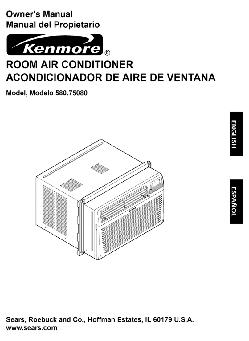
Kenmore Kenmore 580.75051 User manual

Kenmore

Kenmore Kenmore 580.75051 User manual

Kenmore 75051 - 5,300 BTU Single Room Air... User manual

Kenmore

Kenmore 75051 - 5,300 BTU Single Room Air... User manual

Kenmore 580. 75063 User manual

Kenmore

Kenmore 580. 75063 User manual
Kenmore 580.77157710 User manual

Kenmore

Kenmore 580.77157710 User manual

Kenmore 580.75281 User manual

Kenmore

Kenmore 580.75281 User manual

Kenmore 580.74054 User manual

Kenmore

Kenmore 580.74054 User manual

Kenmore 75062 6,000 User manual

Kenmore

Kenmore 75062 6,000 User manual

Kenmore 580.73069300 User manual

Kenmore

Kenmore 580.73069300 User manual

Kenmore Kenmore 580.72087200 User manual

Kenmore

Kenmore Kenmore 580.72087200 User manual

Kenmore 25376110413 User manual

Kenmore

Kenmore 25376110413 User manual

Kenmore 580.71056 User manual

Kenmore

Kenmore 580.71056 User manual

Kenmore 253.76180 User manual

Kenmore

Kenmore 253.76180 User manual

Kenmore 580.75281 User manual

Kenmore

Kenmore 580.75281 User manual

Kenmore 25376085410 User manual

Kenmore

Kenmore 25376085410 User manual

Kenmore 580 User manual

Kenmore

Kenmore 580 User manual

Kenmore Kenmore Room Air Conditioners User manual

Kenmore

Kenmore Kenmore Room Air Conditioners User manual

Kenmore 253.70062 User manual

Kenmore

Kenmore 253.70062 User manual

Kenmore 580.71122 User manual

Kenmore

Kenmore 580.71122 User manual
Kenmore 25370101017 User manual

Kenmore

Kenmore 25370101017 User manual

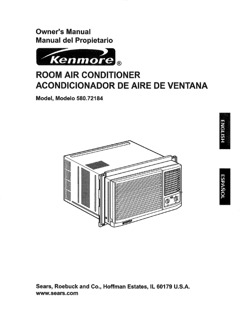
Kenmore 580.72184 User manual

Kenmore

Kenmore 580.72184 User manual

Kenmore 580.74053300 User manual

Kenmore

Kenmore 580.74053300 User manual

Kenmore 66121615 User manual

Kenmore

Kenmore 66121615 User manual

Kenmore 580.76081 User manual

Kenmore

Kenmore 580.76081 User manual

Kenmore 580.74184 User manual

Kenmore

Kenmore 580.74184 User manual

Popular Air Conditioner manuals by other brands

Haier SAP-KRV9AV instruction manual

Haier

Haier SAP-KRV9AV instruction manual

Acson WSS10A installation manual

Acson

Acson WSS10A installation manual

Toshiba RAS-07UKH Srevice manual

Toshiba

Toshiba RAS-07UKH Srevice manual

Samsung AQV24PSBANXAX Service manual

Samsung

Samsung AQV24PSBANXAX Service manual

Sanyo 18KS72 Submittal data

Sanyo

Sanyo 18KS72 Submittal data

Samsung AR36BSHUMGMNCV Service manual

Samsung

Samsung AR36BSHUMGMNCV Service manual

Panasonic S-3650PK3E operating instructions

Panasonic

Panasonic S-3650PK3E operating instructions

Elba EAC-B1081RC owner's manual

Elba

Elba EAC-B1081RC owner's manual

Carrier 40WAU Series Installation and maintenance instructions

Carrier

Carrier 40WAU Series Installation and maintenance instructions

Costway FP10123US user manual

Costway

Costway FP10123US user manual

Mitsubishi Electric Mr. Slim PCA-RP-HAQ installation guide

Mitsubishi Electric

Mitsubishi Electric Mr. Slim PCA-RP-HAQ installation guide

Daikin FTXTJ30A2V1BW installation manual

Daikin

Daikin FTXTJ30A2V1BW installation manual

Toshiba RAV-SM564UT-K owner's manual

Toshiba

Toshiba RAV-SM564UT-K owner's manual

Daikin FXSQ05TAVJU engineering data

Daikin

Daikin FXSQ05TAVJU engineering data

Toshiba RAV-SM406BTP-E1 owner's manual

Toshiba

Toshiba RAV-SM406BTP-E1 owner's manual

GE Appliances Zoneline 2800 Owner's manual and installation instructions

GE

GE Appliances Zoneline 2800 Owner's manual and installation instructions

Friedrich M30CF Service manual

Friedrich

Friedrich M30CF Service manual

Samsung MH080FXCA4A installation manual

Samsung

Samsung MH080FXCA4A installation manual

manuals.online logo
manuals.online logoBrands
  • About & Mission
  • Contact us
  • Privacy Policy
  • Terms and Conditions

Copyright 2025 Manuals.Online. All Rights Reserved.