Kennedy T556 User manual

IN TRUCTION MANUAL
TROLLEY JACK
QUALITY GUARANTEE & WARRANTY
KE EDY TOOLS carry a one year manufacturers warranty.
KE EDY TOOLS are designed & manufactured
to the highest standards & specifications.
Assuring the quality and performance required by all sectors of industry.
KE EDY TOOLS are fully guaranteed against
faulty materials & workmanship.
Should they be found to be defective, they will either be repaired or replaced
free of charge (fair wear and tear and/or misuse excepted).
Please retain supplier invoice as proof of purchase.
© The Kennedy Group Ltd. 06/2014
www.kennedy-tools.co.uk
E C MACHINERY DIRECTIVE 2006/42/EC
DECLARATION OF CONFORMITY
We hereby certify that KE EDY Trolley Jacks
Models T556 & T1056
comply with all the relevant provisions of the EC Directive 2006/42/EC
(The Machinery Directive of the Council of European Communities)
Harmonised Standards Applied: prEN 1494:1994
ational Standards Applied: DIN 76024 01.84
Manufactured for
KENNEDY TOOL
Wigston Works, Leicester, England, LE18 2FS.
www.kennedy-tools.co.uk
Signed:
Date: 14th ctober 2014
ame: Keith Read
Position: HSQE Manager.
AVAILABLE FROM YOUR DI TRIBUTOR
MODEL T556
KEN-503-6380K
TONNE
5
MODEL T1056
KEN-503-6420K
TONNE
10
lFor heavy duty use
lConstructed from heavy gauge steel
lAutomatic safety overload protection
lHandle tilts and locks in three positions
lFoot pedal pump and fine adjustment on handle for optimum vehicle height
lExtra long handle for easy access under bigger vehicles
lHandle mounted safety release prevents accidental lowering of the load
lLarge diameter saddle for a secure hold under the jacking point
lRear toe plate for easy positioning

2
KENNEDY
thoroughly recommends reading these instructions before using the trolley
jack, even if you have used a trolley jack on a vehicle before. Reading these instructions
carefully and understanding them fully will enable you to raise a vehicle correctly and will
prevent injury to yourself or someone else as well as damage to the vehicle and equipment.
Because this product is also used in conjunction with axle stands, please follow all
relevant safety instructions regarding the lifting and supporting of vehicles.
AFETY GUIDELINE
BEFORE USI G FOR THE FIRST TIME, THE TROLLEY JACK WILL EED BLEEDI G.
PLEASE SEE PAGE 6 FOR FURTHER I STRUCTIO S.
lAlways take care to avoid injury when carrying or moving the jack.
lAlways check vehicle owner’s manual for correct vehicle weight.
lAlways use on specified jacking points, on a level surface and with a solid
foundation.
lAlways check that jacking points are not corroded before use.
lAlways engage the handbrake before the vehicle is lifted and use wheel chocks
at the end of the vehicle opposite the jack to guard against wheel movement.
lever use for manoeuvring vehicles.
lever use the jack if you suspect a fault. See the ‘Trouble Shooting’ section on
page 6 for further information.
lever lift a car when somebody is under it, even with secure axle stands.
lever work under a vehicle only supported by a jack. After lifting the vehicle,
support immediately with properly rated axle stands.
lever exceed the rated load capacity or tamper with the factory set overload
valve.
lever lean against the raised vehicle.
lever modify the jack, it is not designed to support extensions or cradles and
could become unsafe.
QUALITY KENNEDY AUTOMOTIVE PRODUCT
AVAILABLE FROM YOUR DI TRIBUTOR

6 3
COMMON REFERENCE POINT
1 tonne (metric ton or t) = 1000Kg 1 ton (imperial ton) = 2240lbs (1016Kg)
Model Max Load Min Max Saddle Handle Handle Chassis Chassis Chassis Net rder
Number (Kg/Tonne) Height Height Ø Pieces Length Length Width Height Weight Code
(mm) (mm) (mm) (mm) (mm) (mm) (mm) (mm) (Kg) KE -503
T238 2,000/2 130 380 50 1 530 530 220 140 12.0 -6320K
T2.249 2,250/2.25 145 495 130 2 1,000 650 350 150 36.5 -6350K
T280 2,000/2 140 800 135 1 1,200 1,200 440 180 58.0 -6920K
T349 3,000/3 145 490 120 2 1,000 630 340 150 39.5 -7100K
T556 5,000/5 150 560 130 1 1,200 1,420 370 200 95.0 -6380K
T1056 10,000/10 160 560 150 1 1,200 1,555 490 255 145.0 -6420K
THE FULL RANGE OF KENNEDY TROLLEY JACK
Valve release knob il filler plug
Grease nipple
Pump handle
Control rod
Saddle
Cover plate
Handle bolt
Foot lever
Toe plate
Lifting arm
Included in the trolley jack box, is one replacement washer and one
rubber ‘ ’ ring. Please keep these in a safe place, in case they are
needed in the future. See page 6 for more information on trouble
shooting.
‘ ’ ringWasher
PARE
For spare parts or servicing please contact your nearest agent. Remember to quote tool model number and
spare part number when ordering spares. The use of other than genuine Kennedy replacement parts may
result in safety hazards, decreased tool performance and increased maintenance. When disposing of
components, etc. ensure that relevant environmental procedures are carried out.
KE -503-6380K
Jack handle assembly: KEN-567-7800K
Replacement front wheel: KEN-567-9260K
Replacement rear castor: KEN-567-9270K
Trolley jack valve release knob: KEN-567-5496K
KE -503-6420K
Jack handle assembly: KEN-567-7800K
Replacement front wheel: KEN-567-9280K
Replacement rear castor: KEN-567-9290K
Trolley jack valve release knob: KEN-567-5496K
Seal repair kit: KEN-567-9220K

4 5
OPERATING
Before using the trolley jack for the first time, bleed the hydraulic system to remove any air.
Please see page 6 for bleeding instructions.
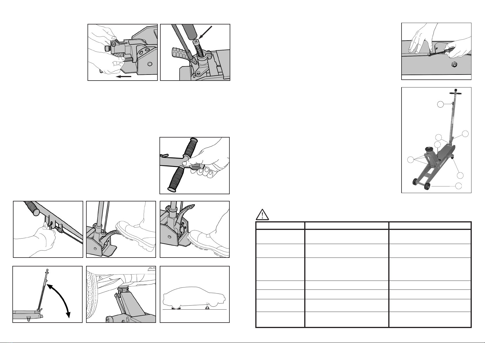
1. Turn the release valve clockwise until it can no longer be turned (See fig. 3).
2. Lower the handle to a convenient angle by pulling the control rod up (See fig. 4). Ensure the control rod is
locked into position in one of the three holes.
3. Pump the foot pedal to move the saddle to just under the correct height (See fig 5).
4. Use the toe plate to help position the trolley jack underneath the
vehicle (See fig. 6).
5. To help with positioning, the handle can also be locked in three
positions (See fig.7)
6. Pump the handle to raise the saddle into the correct position. Please
refer to the “Car owner’s manual” for the correct jacking points.
7. Check positioning under a slight load to make sure the jack will not slip
when in use (See fig 8). Continue to lift the load.
8. nce the load has been raised to the required height, use an additional
support (i.e. correctly rated stands) before continuing work (See fig 9).
9. To lower the vehicle, remove the additional supports. Turn the handle
anti-clockwise. The speed at which the vehicle is lowered can be
controlled easily by how much and how quickly the release valve is
turned.
TOOLS EEDED: Either two 17mm
sockets or two 17mm spanners.
1. Remove and dispose of the
metal rod which is holding the
handle socket down (See fig. 1).
2. Position the handle over the
spring. Push it down whilst
ensuring that the control rod is
located in the top securing hole
(See fig. 2). Tighten the handle
bolt securely and test to make
sure the handle will not pull out.
A EMBLY
fig. 2
fig. 1
fig. 3
fig. 5 fig. 6
fig. 9
fig. 7 fig. 8
fig. 4
TROUBLE HOOTING
PO IBLE CAU E
1. Low oil level.
2. Air has entered the hydraulics.
3. Ram seal leaking.
1. The release valve has not been fully
closed.
2. The oil level is low.
1. The release valve has not been fully
closed.
2. The oil level is low.
3. The hydraulic system has become
blocked by dirt particles.
1. The hydraulic system has become
blocked by dirt particles.
1. The hydraulic system has become
blocked by dirt particles.
1. Worn or damaged seals.
1. Low oil level.
2. Air in the system.
OLUTION
1. Fill to correct oil level.
2. Bleed the hydraulic system.
3. Replace worn seals
1. Turn the release valve clockwise until
it can no longer be turned.
2. See refilling instructions.
1. Turn the release valve clockwise
until it can no longer be turned.
2. See refilling instructions.
3. Turn the release valve anti-clockwise
and push the piston down quickly.
1. Turn the release valve anti-clockwise
and push the piston down quickly.
1. Turn the release valve anti-clockwise
and push the piston down quickly.
1. Replace worn seals. Look for
excessive contamination or wear.
Replace contaminated oil.
1. Fill to correct oil level.
2. Follow instructions to bleed air from
the system.
FAULT
Unit fails to extend or
extends partially.
The jack will not lift the
rated load.
The jack lowers under
load.
The hydraulic system
will not lower.
The handle raises or
springs back under load
Ram leaks hydraulic oil.
Incomplete or spongy
cylinder response when
foot pedal is pumped.
Repairs must be performed in a dirt-free environment by a qualified person who is familiar with this type
of equipment.
CARE & MAINTENANCE
Periodically check the operation of the jack. Ensure all nuts are fully
tightened and all other fixings are in position and secure. Do not use the
trolley jack if you suspect a fault but refer to the fault finder section below.
To gain access to the hydraulic pump, remove the cover plate using a flat
headed screwdriver (See fig 10).
CHECKING & FILLING THE OIL RE ERVOIR:
1. Place the jack on level ground
2. Always follow the precautions advised by the oil manufacturer.
3. Lower the jack to the lowest position.
4. Remove the rubber filler plug from the cylinder housing. Using hydraulic
oil ISO VG.22.32, fill until the inner cylinder is covered. D N T USE
BRAKE FLUID.
5. Pump the trolley jack unloaded 5 or 6 times to expel air.
6. Add more oil if necessary.
7. Refit the filler plug.
BLEEDING THE Y TEM:
1. Turn the release valve anti-clockwise no more than one complete turn.
2. Remove the rubber oil stopper from the cylinder housing.
3. Pump the handle several times to force out any air.
4. Turn the release valve clockwise until it can no longer be turned.
5. Replace the rubber stopper.
LUBRICATING:
Lubricate the points as indicated in fig.11.
a. HA DLE. Use light oil on moving parts.
b. REAR WHEELS. Use light oil on axles and castor bearings.
c. LIFTI G ARM. Inject grease into grease fitting.
d. SADDLE & LI KAGE. Use light oil on all moving and pivoting parts.
e. HA DLE SOCKET PIVOT BOLTS. Use light oil to lubricate pivot bolts.
f. FOOT PEDAL. Use light oil on moving parts.
g. FRO T WHEELS. Inject grease into grease fitting.
WHEN NOT IN U E:
Wipe clean with a slightly oiled cloth. Store with the release valve open.
a
e
d
c
b
g
f
fig. 10
fig. 11
This manual suits for next models
3
Other Kennedy Jack manuals
Popular Jack manuals by other brands

Tronair
Tronair 02A7843-0112 Operation & service manual

Clarke
Clarke STRONG-ARM CTJ2QLP Operation & maintenance instructions

Pro-Lift
Pro-Lift F1800 owner's manual

BE Ag & Industrial
BE Ag & Industrial 35.400.102 Operating instructions manual

Mountain
Mountain MTN5505A quick start guide

Gigant
Gigant 11948-0101 Installation and operating instructions