1.
GENERAL
The
FC-757
isa universalcounter.Itcanbeusedto
measure
frequencies(175MHzMax.),period,frequency
ratio,
total
number,andtimeinterval.Eventinputs
can
bealsocounted
with
thecounter.
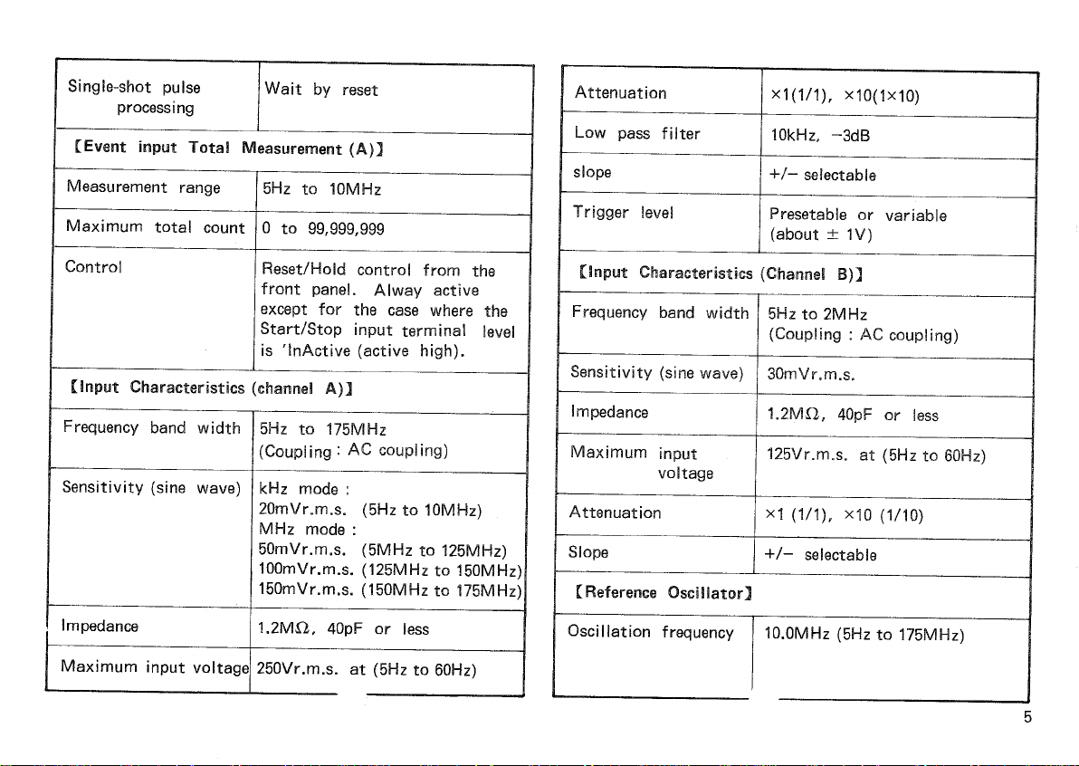
Channel
A isan
input
channelterminated
with
a
resistor
of1.2MOandusedtomeasurethefrequencies
between5Hzand175MHz,periodandthe
total
number
ofeventinputs.
Channel
B isan
input
channelterminated
with
a
resistor
of1.2MI2andusedtomeasurefrequencyratio
andtimeinterval.Thesignalsintherange
from
5Hz
to2MHzcanbe
input.
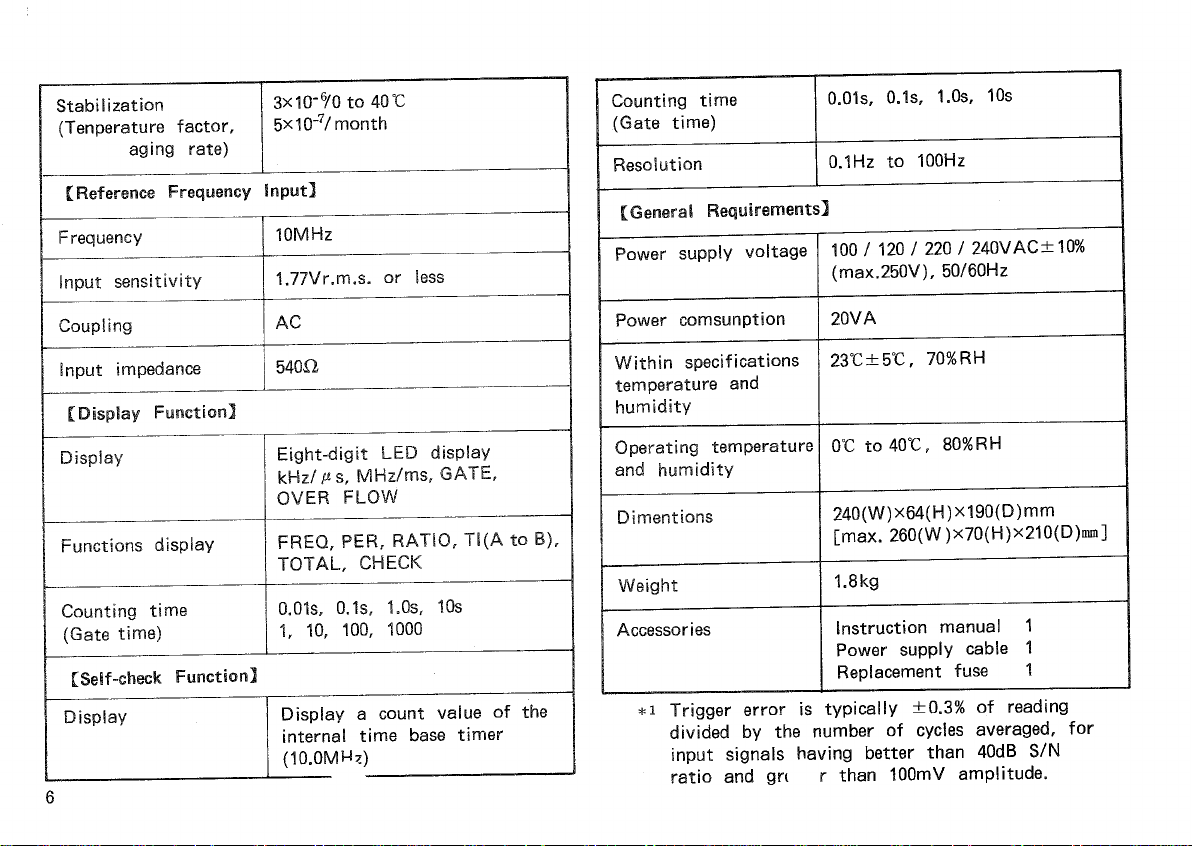
The
FC-757
universalcounterhasan
8-digit
high-
brightnessLEDdisplay.Thehighestdisplayresolution
is
0.1Hz.
The
FC-757
isa highlyfunctionaladvanceduniversal
counter
with
the
following
functions.
-Periodmeasurementfunction
The
periodmeasurementfunctionisusedtomeasure
theperiodofeach
input
signal.
This
functionwould
output
higher-precisionmeasurementdatainrelatively
lowfrequencyoperationmode.
—Timemeasurementfunction
The
timemeasurementfunctionisusedtomeasure
theintervaltimebetweenanytwoedgesof
differenttwosignals,andbetweentwo'single-shot'
pulse
signals.
-EventInput
total
countmeasurementfunction
The
event
input
total
countmeasurementfunction
is
usedtomeasurethe
total
numberofeventinputs
tothecounter.
This
functioncanbecontrolled
through
paneloperationsorby
inputting
gate
signais
externally.
Inaddition,the
FC-757
universalcounterhasa
self-check
function.Withthischeckfunction,major
measurementfunctionscanbetested.
The
displayfunctionsupportsa leading-zeroblanking
andconsistsofmany
LEDs
indicatinga measurement
unit,
gateactivityandoverflowoccurrence.
The
FC-757
multi-functionalcounterhasa highstable
crystal
oscillatorasthetimebaseclockgenerator.
Therefore,
highaccuracymeasurementisnotadversely
affectedbyfluctuationsintemperatureandpower
supplyvoltage.
3