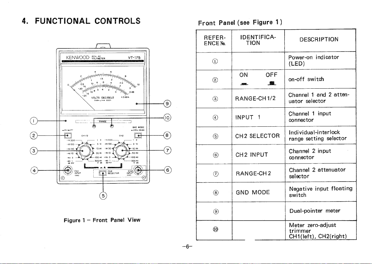
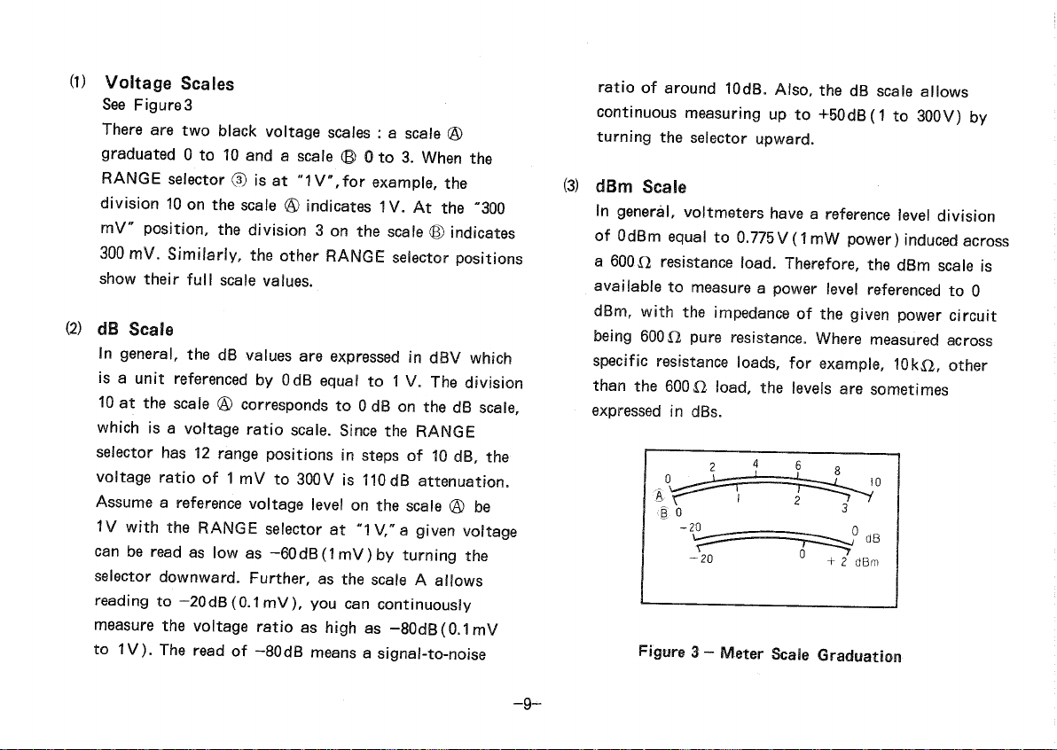
Kenwood VT-175 User manual

©PRINTED
INPAN
KENWOOD
2
CHANNELACVOLTMETER
VT-175
INSTRUCTIONMANUAL
KENWOOD
CORPORATION

CONTENTS
1.
GENERAL3
2.
FEATURES
3
3.
SPECIFICATIONS
4
4.
FUNCTIONAL
CONTROLS6
5.
OPERATION8
6.APPLICATIONS10
7.
MAINTENANCE13
8.ALIGNMENT14
9.CAUTIONSFORUSE••16
-2-

1.
GENERAL
2.
FEATURES
The
Model
VT-175
isdual-channelelectronicvoltmeter
sets
havingtwoindependentACvoltmetersina single
cabinet.Two-pointermeterallows
easy
dualmeasurements
andinter-channelcomparisons.
MODEL
VT-175
iswideband,highsensitivevoltmeterfor
use
anywherevoltagemeasurementsaremade,
with
a
remotecontrol
unit.
Theeasy-to-usevoltmeterprovides
frequencyresponseaswideas5Hzto
1
MHz,measurable
range
from
1mVto300V,and
input
impedanceof
10MO.
a.
Twopowersourcecircuits,positiveandnegative,
are
providedforverystableDCbiasandrecover
from
anyoverloadina veryshorttime.
b.Small-sizedcompactconstructionis
easy
tocarry
andlarge-sizedtwo-pointermeteris
easy
toread.
c.
Four-scaledialplateandredandblackpointers
allowquick,andaccuratevoltagereading.
d.
Numberofadjustingtrimmersareminimized
with
amplifiersthatarepreciselycalculatedinopen
loop
gains
andarenegativefeedbacked
through
metal-
film
resistorsasaccurateas1%
Amplifiercharacteristicsthereforeare
from
secular
change.
e.
Inputimpedanceisashighas10MOonallranges
anditsparallelcapacitance
less
than45pF
f.IndirectattenuatorswitchingbyrelayandFET
(field-effecttransistor)switchprovideshigher
reliability,signal-to-noiseratio,andinter-channel
crosstalk
thanmostpreviousdirectmethodofrotary
switch.
-3-

9-
RangescanberemotelyselectedusingtheRT-61
(option).
h.Twochannelrange
setting
canbemadeeither
individually
or
together
(ininterlockedmanner).
i.A
ground
mode
selectormay
float
measuringcircuit
aboveground.
3.SPECIFICATIONS
[Meter
Section]
Measurablevoltages:
1
mV-300Vin12ranges:
1
mV,3mV,10mV,30mVr100mV,
300mV,1V,3 V,10V,30V,100Vand
300V.
full
scales.
dB:
-80~+50dB(0dB= 1V).
dBm: -80~+52dBm(0dBm=
1
mW,600n).
Error
:
Within
± 3%of
full
scaleat1kHz.
Frequencyresponse: ± 10%at5Hz—
1
MHz,
±5%at10Hz-500kHzand
±3%at20Hz-200kHzas
±2%
at30Hz~100kHz
referencedto
1
kHzresponse.
Input
impedance: 10MO±5%,
with
less
than
45pF
parallelcapacitance.
Durable
input
voltage:500V(DC+ACpeak)
at1V—300Vrange
100V(DC+AC
peak)
at1mV~300mVrange
Stability: Within±0.5%of
full
scale
fori
10%
linevoltage
fluctuation.
-4-

-5-
Residual
voltage:
Less
than
20^V
with
input
shorted
on
1
mVrange-
Crosstalk,Individual:
Less
than
-80dB
with
other
input
terminated
with
600O
Inetrlock:
Less
than
-50dB
with
other
input
terminated
with
600O.
[Amplifier
Section]
Gain
: Approx.60dB.
Output
voltage: 1Vrms(Full
scale)
±20%
Output
impedance:600X1+20%
Distortion
:
Less
than
1%at
full
scale.
(Rated
bysignal-to-noise
ratio
in
1
mVand
1V
ranges.)
Signal-to-noise
ratio:
Over40dBat
full
scale.
Frequencyresponse:
Within
± 3dBat5 Hz—500kHz
[Environmental]
Coefficient:± 0.08%/°C
Temperature
(within
specification): 10~40°C
(full
operation):
0~50°C
Relative
humidity
:
Less
than
80%
[PowerSupplySection]
Line
voltage: 100,120,220VAC+ 10%,
216- 250VAC,50/60Hz
Powerconsumption:Approx.7W
[Dimensions]Wx190(212)Hx238(268)Dmm.
Values
in( ) includeprotrusions.
[Net
weight]
3 kg
[Accessories
]
Powercable:
1
pc.
Input
cable: BNCcord,2pes.
Replacementfuse: 0.3A2pes.
0.5A 2pes.
Instruction
manual:
1
copy.

4.FUNCTIONALCONTROLS FrontPanel(seeFigure1)
Figure
1 - FrontPanelView
REFER-
ENCED.
IDENTIFICA-
TION
DESCRIPTION
® Power-onindicator
(LED)
© ONOFF
on-off
switch
©
RANGE-CH
1/2
Channel
1 and2 atten-
uatorselector
®
INPUT
1
Channel
1
input
connector
©
CH2
SELECTOR
Individual-interlock
rangesettingselector
©
CH2
INPUT
Channel
2
input
connector
©
RANGE-CH
2
Channel
2 attenuator
selector
©
GND
MODE Negative
input
floating
switch
© Dual-pointermeter
® Meterzero-adjust
trimmer
•CH1(left),CH2(right}
-6-

RearPanel(seeFigure2)
Figure2 - RearPanelView
REFERE-
NCE
No.
IDENTSFSCA-
.TION
DESCRIPTION
® GND
Casing
grounding
post
@
CH2
OUTPUT Channel2
monitor
output
connector
® Line
voltage
selector
andfuse
holder
® Power
Gable
connector
©
CH1
OUTP' Channel1
monitor
output
connector
©
CONT.
INPUT Remote
control
mounting
hole
_7_

5.OPERATION
•Set-up
(1)
Press
the
ON/OFF
Pushswitch©in.ThePower-on
indicator®,a
light-emitting
diode,will
light,
indicat-
ingthatpowerhasbeenapplied.
(2)
Plugthesignalcalbes
into
theCH1
INPUT
andCH2
INPUT
connectors® and© .
(3)
CH2SELECTOR©,
with
theswitch
released(JH),
takes
singlemodeinwhich
Ranges
CH
1
andCH2 are
changedoverugingAttenuatorsCH1/2©andCH2®,
respectively.'
. ' •
Withtheswitchpressed
(-—-),
the
SELECTOR
takes
interlockmodeinwhich
both
Ranges
CH
1
andCH2
are
simultane-ouslychangedoverusingAttenuator
CH
1/2®.Intheinterlookmode,AttenuatorCH2®
is
nolongeroperabletoselecta
Range.
Select
eithersingleorinterlookmodeaccordingto
yourparticularmeasurement.
(4)
Setthe
RANGE-CH
1/2selector©andthe
RANGE-
CH2
selector® to"300V/TomeasureanACvoltage
superimposedona DCvoltage,besuretosetthe
selectors
tothepositionsbeforeconnectingthecables
topointstobemeasured.rerwise,theDCvoltage
causes
a highsurge,whichcouldburnvoltmeter.
(5)
GNDMODE®iseffected
with
theswitchreleased
(•)r
inwhich
both
CH
1
andCH2areconnectedto
thegroundingterminalofthecasing,takingGND
state,
with
theswitchpressed(-•».),thegroundingof
CH
1
andCH2isfloatedto
OPEN
stateinwhich
youmovetheearth
point
tothesignalsourceside.
NormallyusethedeviceintheGNDstate.
(6)
Connectthecablestopointstobemeasure.
(7)
Turntheselectors® and© forproperranges
until
each
Meterpointerswitngsoverone
third
ofthe
fullscale.
(8)
OUTPUTS
CH2@ andCH
1
@ provide
output
signals
byamplifying
input
signalsinsuch
a
degreeasthesignalamplitudeofa meterfull-
scale
becomes1 Vrmsnomatterwhichrangeisset.
(9)
Read
theMeter.
-8-

(1)
Voltage
Scales
See
Figures
There
aretwoblackvoltage
scales
: a
scale
®
graduated0 to10anda
scale
© 0 to3.Whenthe
RANGE
selector® isat"1V,forexample,the
division10onthe
scale
® indicates1V.Atthe"300
mV"position,thedivision3 onthe
scale
® indicates
300
mV.Similarly,theother
RANGE
selectorpositions
showtheir
full
scale
values.
(2)
dB
Scale
Ingeneral,thedBvaluesareexpressedindBVwhich
is
a
unit
referencedbyOdBequalto1 V.Thedivision
10
atthe
scale
® correspondsto0 dBonthedB
scale,
whichisa voltage
ratio
scale.
Sincethe
RANGE
selectorhas12rangepositionsinstepsof10dB,the
voltage
ratio
of1 mVto300Vis110dBattenuation.
Assume
a referencevoltagelevelonthe
scale
® be
1V
with
the
RANGE
selectorat"1V,"a givenvoltage
can
bereadaslowas-60dB(1mV)by
turning
the
selectordownward.Further,asthe
scale
A allows
readingto—20dB(0.1mV),youcancontinuously
measure
thevoltage
ratio
as
high
as-80dB(0.1mV
to1V).Thereadof-80dBmeansa signal-to-noise
ratio
ofaround10dB.Also,thedB
scale
allows
continuousmeasuringupto+50dB(1to300V)by
turning
theselectorupward.
(3)
dBm
Scale
Ingeneral,voltmetershavea referenceleveldivision
ofOdBmequalto0.775V(1mWpower)inducedacross
a
800Oresistanceload.Therefore,thedBm
scale
is
available
tomeasurea powerlevelreferencedto0
dBm,
with
theimpedanceofthegivenpowercircuit
being60012pureresistance.Wheremeasuredacross
specific
resistanceloads,forexample,10kO,other
thanthe600Oload,thelevelsaresometimes
expressed
indBs.
Figure
3 - Meter
Scale
Graduation
™9-

•HowtoUseRemoteControl 6.APPLICATIONS
The
RT-61option,a remarkablefeatureofthe
VT-175,
providesa remotecontrolcapability.Tousetheoption,
removethe
case
andtherear-panelblindplate,install
theconnectorsuppliedwiththe
RT-61,
thenplugthe
RT-61
into
the16-pinconnectoronthe
print
circuit
board.
Fordetails,refertotheRT-61Instruction
Manual.
The
basic
useofyourvoltmeteristomeasuresinusoidal
wave
voltagesasanACvoltmeter.Inaddition,it
providesa widevarietyofapplicationsasdescribed
below.
AmplifierGainMeasurement
Voltmeteriscapableofmeasuringanamplifiergain,
whichisa signalmagnificationfrom
point
A toB in
Figure
4 witha signalgeneratorconnectedtotheamplifier
input.IfthemeasuredsignallevelsatpointsA andB
are
a andb dB,respectively,thenthegainis(b-a)dB.
Figure
4 - AmplifierGainMeasurement
Also
themethodisapplicableformeasuringanopen
loop
gainofeachamplifiercircuitwiththenegative-
feedback
signal
leaves
applied.Further,themethodc
beusedformeasi"thefrequencyresponsesofgiv
SIGNAL
GENERATOR
-10-

circuitsbychangingthesignalgeneratorfrequency.
Voltmeteriscapableofdirectlyreadinga gainbetween
twopointsashavingtwoindependentvoltmeters.Asan
example,
letuscalculatetheopen
loop
gain(from
point
A
toB)ofthenegative-feedbackamplifiershowninFigure
5.
Assumethatthemeasuredlevelat
point
A be+1.5dB
onthe-60dBrangeofthechannel1 andthatof
point
B
-4dB
onthe-MOdBrangeofthechannel2.Thegain
from
point
A toB isthen
(
+
10dB-4dB)-(-60dB+1.5dB)
= 64.5dB.
SIGNAL
GENERATOR
Figure
5 - NegativeFeedbackAmplifier
Gain
Measurement:
VoltageCalculationsofSomeSpecialWaveforms
Anvoltmeterofabsolute-meanvalueindicationtype,
reads
root-mean-squarevaluesofsinusoidalwaveinputs.
Also
itdeflectsthepointersin
proportion
totheabsolute-
mean
valueofa given
input
wave.
Ifthe
form
factor(=root-mean-squarevalue/absolute-
mean
value)ofthe
input
waveandthecrestfactor( =
peak
value/root-mean-squarevalue)areknown; thenthe
root-mean-squarevalueandpeakvaluecanbecalculated
as
follows.
Assume
theMeterreadx.
•Absolute-meanvalue=x = 0.9x
•Root-mean-squarevalue= (Absolute-meanvalue)x
(Form
factor).
•
Peak
value=(Root-mean-squarevalue)x
(Crest
factor).
For
rectangular
waves,
their
form
factorandcrestfactor
are
unity(1).
2x/2
•Aboslute-meanva!ue=• • x = 0.9x
n
•Root-mean-squarevalue= 0.9x.
•
Peak
value=0.9x.
For
sawtooth
waves,
their
form
factoris
2/<\/3
andthe
crest
factor\/l>.
-11-

(1)
Frequencyresponse
Ways
ToBetterDual-ChannelVoltmeterOperation
The
two
input
channelsandtwometerpointersarranged
specifically
inVoltmeteraremostusefulformeasuring
an
electronicequipmenthavingtwosignalsources.
For
example,Voltmeterisfarmoreconvenientfor
measuringstereo
left
and
right
channelcharacteristics
thanusingtwounitsunitsofusualsingle-channel
voltmeter.
STEREO
AMP
CH2SELECTOR
swichtopressed(interlockposition)
as
moststereoamplifiersarenotdeviated
vertuallyinthe
left
and
right
channellevels.Setthe
GND
MODEswitchto"GND."Ifthegivenstereo
amplifier
output
hasnoconnectorcommontothe
left
and
right
channels,then
turnt
heswitchto
"OPEN
"and
connecttheGNDpostontherearpanelofvoltmeterto
thatofthestereoamplifier.'
-12-
2«/2
•Absolute-meanvalue=• x = 0.9x.
it
2«/2 2
•Root-mean-squarevalue=——-x •——x =
7u
v 3
4x/2
——x = 1.04x
TTVO
4<s/2 ^ 4V2
•
Peak
value=-xv3x = -~x = 1.8x.
TV
v
3
71
Rch
Lch
Figure
6 - StereoAmplitierFrequency
Response
Measurement

(2)Crosstalkcharacteristic 7.MAINTENANCE
Crosstalk
measurementisneededifthereisa large
differencebetweenthe
left
and
right
channel
output
levels.
CH2
SELECTOR
Pushbuttontorelease(individual
position).Setthe
RANGE-CH
1/2selectorand
RANGE-
CH2
selectortoproperposi-tionsfor
ease
ofread.Set
theGNDMODEswitchfornoadverseeffectbyhumas
explainedinaboveExample
(1),
the"Frequencyresponse."
Replacing
the
fuse
(seeFigure8)
REPLACING
FUSE
Whena fusegoesout,thedeviceisnolongeroperable.
Ifgoneout,checkfora
trouble
cause,
remedyit,remove
thecapofthefuseholderontherearpanelusinga
minusscrewdriverandtakeitoutandreplacethefuse
with
a newone.
Whenreplacingfuse,besuretocheckthecapacityofa
newfusefora specifiedvalueasfollows:
AC
100V,120V: 0.5A
AC
220V,240V: 0.3A
CHANGEOVER
OF
VOLTAGE
IN
SWITCHING
REGULATOR
Remove
thefuseholderontherearsideofthedevice
set,
usinga minussurewdriver,adjustyourpreferred
voltageindication
with
• markand
plug
theholderin.
For
changing100Vor120Vto220Vor240V,changethe
fuse
of0.5Ato
that
of0.3A.
-13-
STEREO
AMPj
SHORT
Figure
7 - StereoAmplifierCrosstalk
Measurement

8.ALIGNMENT
Figure
8 - Replacingthefuse
Voltmeterwaspresicelyalignedatthefactory.However
itcanbealigned
through
theadjustholeslocatedonthe
side
with
leavingishousedinthe
casing,
ifrequired.In
realignment,firstadjustthelinetotheratedvoltage,use
a
preciselycalibratedmeasuringinstruments,andproceed
as
follows.
PresetControlsonSidePanel(seeFigure9)
The
following
controls,placedontheMainPCboard,are
tobepresetontheright-handsidepanel.
IDENTIFICA-
TION
DESCRIPTION
TC101
First
Attenuatorpresettrimmer
capacitor
VR101
First
Attenuatorpresetvariable
resistor
VR102
MeterAmplifiergainpreset
variableresistor
1.
Before
turning
the
ON/OFF
switch"ON,"adjustthe
Meterzero-adjust
screws
(rightforchannel1 and
left
forchannel2)onthe
front
panel
until
thepointers
correctlyindica"01
-14-

12.
AdjustTC101
until
thepointerswingstothefull-
scale.
13.
Repeat
Steps
3 through10.
14.
Forchannel2 alignment,similaryproceedwith
Steps
3 through13.
CH
1
CH2
-15-
Flgure
9 -
Pres
ControlsonSidePanel
2.
SettheCH2
SELECTOR
pushbattonto
release
(individualposition).
3.
Connecta voltmetercalibrator1 kHz(or400Hz)
output
tothe
INPUT
connector®.
4.
Setthe
RANGE-CH
1/2selector®onyour
VT-165
to
the"30mV"rangeandsetthevoltmetercalibrator
output
voltageto30mV.
5.
Adjust
VR102
until
thepointerswingstothefullscale.
6.
Inturn,setthe
RANGE-CH1/2
selector®tothe"10V
range
andsetthevoltmetercalibrator
output
voltageto10V.
7.
AdjustVR101
until
thepointerswingstothefull-
scale.
8.
Disconnectthevoltmetercalibratorandconnecta
widebandsignalgeneratortotheCH
1
INPUT
con-
nector®.
9
Setthesignalgeneratorfrequencyto
1
kHzandset
the
RANGE-CH
1/2selector@ onvoltmetertothe
"IV
range.
10.
Adjustthesignalgenerator
output
level
until
the
pointerswingstothefullscale.
11.
Changethesignalgeneratorfrequencyfrom1 kHzto
50
kHz.

9.CAUTIONSFORUSE
1.
Yourvoltmeterwillworkjustwhenthe
ON/OFF
switch
ispressedin.Foraccuratemeasurements,
waitaroundfiveminutesforwarm-up.
2.
Avoidplacingyourvoltmeterwheremagneticfield
and
electricfieldaretoostrong.
3.
Theinputsignalcableotherthansuppliedshouldbe
low-capacitance
shieldedcable,orcoaxialcable.For
measurements
athigherthanaudiofrequencies,
terminatetheinputconnectorswith500or600O,
resistor.
4.
Thecontinuousmaximuminputvoltageallowablefor
yourvoltmeteris100V
(DC+ACpeak)
withthe
RANGE
selectorat
"-60dB"
to
"-10dB".
Full
careshouldbeobservedinmeasuringhigh
voltages.
5.
Becarefulofa linenoiseandsimilarsmallnoisesas
yourvoltmeterisa highlysensitivevoltmeter.
6.
Donotleaveyour
VT-175
atanyofhightemperature
and
humidityplacesfora longperiodoftime.
7.
Ashavingtwochannelindependentvoltmeter,your
voltmeterisinvolvedinselectionofgrounding
point
onsomeequipmentudnermeasurement.SettheGND
MODE
switchto
"OPEN"
andconnecttheGNDpost
ofyourvoltmetertoa
point
wherenoiseeffectis
minimized.
8.
The
ON/OFF
switchofthisunitisdesignedtoact
onthesecondarysideofthepowertransformer.
The
primarysideofthetransformerremainsenergized
even
ifthe
ON/OFF
switchissettoOFF.Therefore,
iftheunitistobeunusedfora longtime,thepower
cordshouldbeunpluggedfromthereceptacleoutlet.
KENWOOD
CORPORATION
17-5,
2-chome,
Shibuya,
Shibuya-ku,
Tokyo150,Japan
-16™
Table of contents
Other Kenwood Measuring Instrument manuals

Kenwood
Kenwood VT-183 User manual

Kenwood
Kenwood FC-757 User manual

Kenwood
Kenwood FL-180A User manual

Kenwood
Kenwood VT-171 User manual

Kenwood
Kenwood FC-758 User manual

Kenwood
Kenwood VT-173 User manual

Kenwood
Kenwood HM-250 User manual

Kenwood
Kenwood FL-180 User manual

Kenwood
Kenwood FL-140 User manual

Kenwood
Kenwood DM-81 User manual