theOSCterminalontherearpanel,3.15kHz
based
onDINor3.0kHzbasedonJISand
CCIRf
used
forrecordingand
drift
meterselfcalibra-
tion.
®
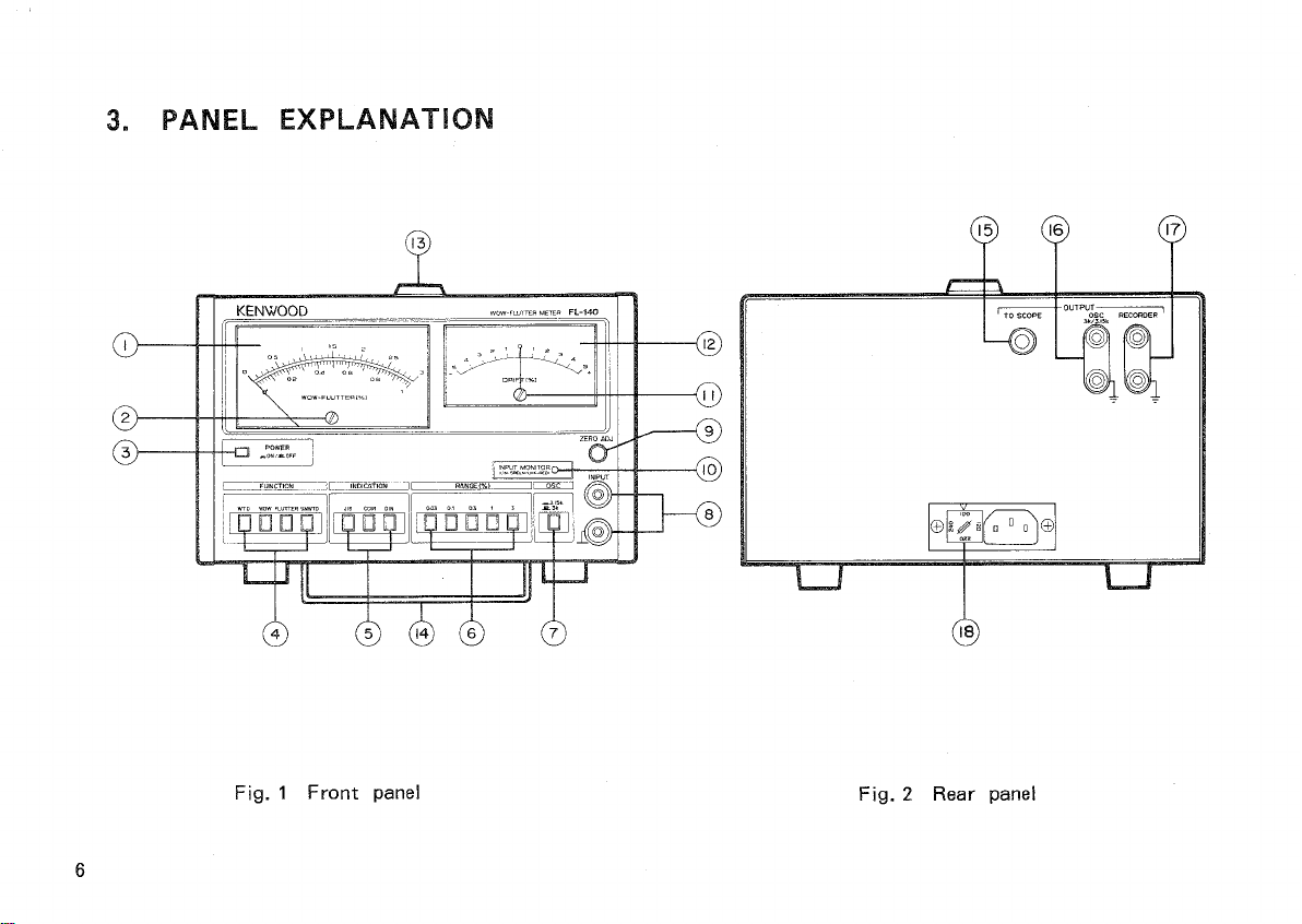
INPUT
terminal
Applythesignaltobemeasuredtothisterminal.
Its
inputimpedanceis300kOandthemaximum
inputvoltageis100V
(DC
+ AC
peak).
@ZERO
ADJUST
control
For
0%calibrationofthe
drift
meter.Adjust
the
drift
meterto0%undertheconditionwhere
noinputisappliedand"the
INPUT
MONITOR
lamplightsred".
IftheDINoftheINDICATIONbuttonsis
pressed,
set
theOSCselectorswitch© to3.15kHzfor0%
calibration.Ifthe
JIS/CCIR
button
is
pressed,
set
OSCto3kHz.
©
INPUT
MONITORlamp
This
lamplightsredifnosignalorimproper
signal
isappliedtothe
INPUT
terminal.
Itlightsgreenifpropersignalisappliedtothe
INPUT
terminal
(i.e.,
theinputfrequencyis3kHz
±300Hzfor
JIS/CCIR
or3.15kHz±300HzforDIN
and
inputlevelis3mVormore).
©Driftmeterzeroadjustscrew
For
adjustmentofthemechanicalzero
point
of
the
drift
meter.Priontoturningonpower,
adjust
themetertotheaccuratezero
point
with
a
Phillipstypescrewdriver.
©Driftmeter(Zerocentertype)•
This
meterreadsthe
drift
oftherevolutionof
a
testpiecetobemeasuredsuchasa tape
recorder.Itmeasuresupto±5%of
drift.
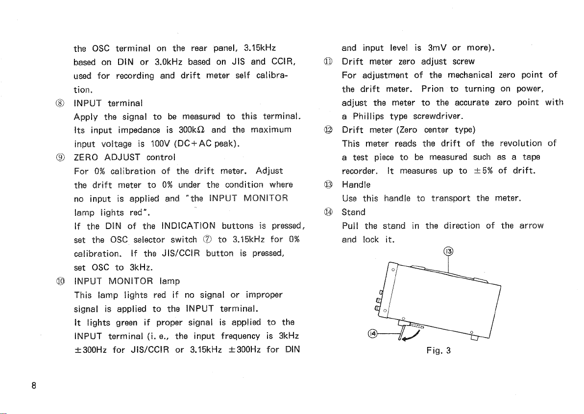
©Handle
Use
thishandletotransportthemeter.
©Stand
Pull
thestandinthedirectionofthearrow
and
lockit.
Fig.
3