KEPCO ES-756 Manual

ES-756
INSTALLATION & OPERATING INSTRUCTIONS
MODELS
ES756 INT-69RT
99914
01/03/06
KESSLER-ELLIS PRODUCTS
10 Industrial Way East
Eatontown, NJ 07724
800-631-2165 • 732-649-7100
Fax: 732-649-7099
http://www
.kep.com

Proprietary Notice
The information contained in this publication is derived in part from proprietary and patent
data. This information has been prepared for the ex pressed purpose of assisting op er at ing
and maintenance personnel in the effi cient use of the in stru ment described herein. Publication
of this information does not convey any rights to use or reproduce it or to use for any purpose
other than in connection with the installation, operation and main te nance of the equipment
described herein.
Copyright 2004
Printed in USA. All Rights Reserved.
WARNING
This instrument contains electronic components that are sus cep tible to damage by static
electricity. Proper han dling* pro ce dures must be observed during the removal, in stal la tion,
or handling of internal cir cuit boards or devices.
*Handling Procedure
1. Power to unit must be removed.
2. Personnel must be grounded, via wrist strap or other safe, suitable means, before any
printed circuit board or other internal device is in stalled, removed or adjusted.
3. Printed circuit boards must be transported in a con duc tive bag or other conductive con-
tainer. Boards must not be re moved from protective enclosure until the im me di ate time of
in stal la tion. Removed boards must be placed im me di ately in protective con tainer for transport,
storage, or return to factory.
Comments
This instrument is not unique in its content of EDS (electro static discharge sensitive) com po -
nents. Most modern elec tronic designs contain components that utilize metal oxide tech nol ogy
(NMOS, CMOS, etc.). Experience has proven that even small amounts of static electricity
can damage or de stroy these devices. Damaged components, even though they ap pear to
function properly, exhibit early failure.

TABLE OF CONTENTS
DESCRIPTION & SPECIFICATIONS
...........................................
1
MOUNTING
..................................................................................
2
WIRING
........................................................................................
3
TYPICAL WIRING HOOKUPS
.....................................................
4
OPEN COLLECTOR
....................................................................
5
PROGRAMMING FLOWCHART
..................................................
6
DEFINITIONS
...............................................................................
7
FRONT PANEL OPERATIONS
....................................................
10
PROGRAMMING
.........................................................................
10
SETTING PRESETS & PANEL LOCK
.........................................
15
TROUBLESHOOTING GUIDE
.....................................................
16
WARRANTY
.................................................................................
WARRANTY .................................................................................WARRANTY
17
DECODING PART NUMBER
.......................................................
19
APPENDIX I - UNITS CONVERSION CHART
.............................
18

THIS PAGE IS BLANK

1
DESCRIPTION & SPECIFICATIONS
Description:
Featuring 6 digits of bright, 7-seg ment LED dis plays,
this unit is an integrating to tal izer/rateme ter which
ac cepts ana log sig nal in puts. The unit can be fi eld
pro grammed to ac cept 0-20mA, 4-20mA, 0-5V, 0-10V
or 1-5V sig nals. A 4-20mA out put op tion is avail able
to control strip re cord ers or other peripherals. Two
as sign able set points are stan dard for two stage shut
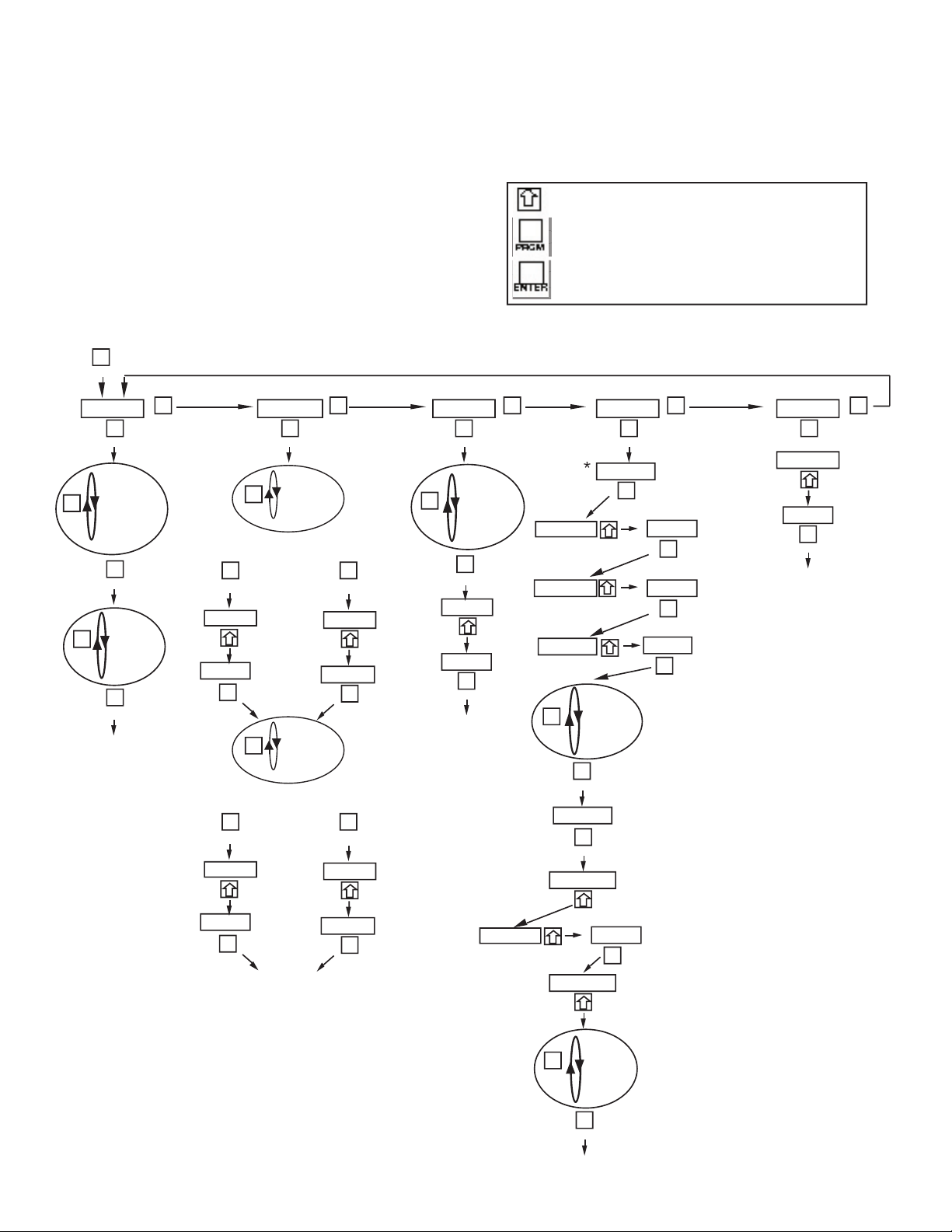
off. The full scale setting is pro gram mable from the
front pan el. By press ing the "view" but ton, the unit
will display: in te grated to tal, rate, peak or valley.
Specifi cations:
Display:
6 digit, .55" high, 7 seg ment, red orange,
LED.
Input Power:
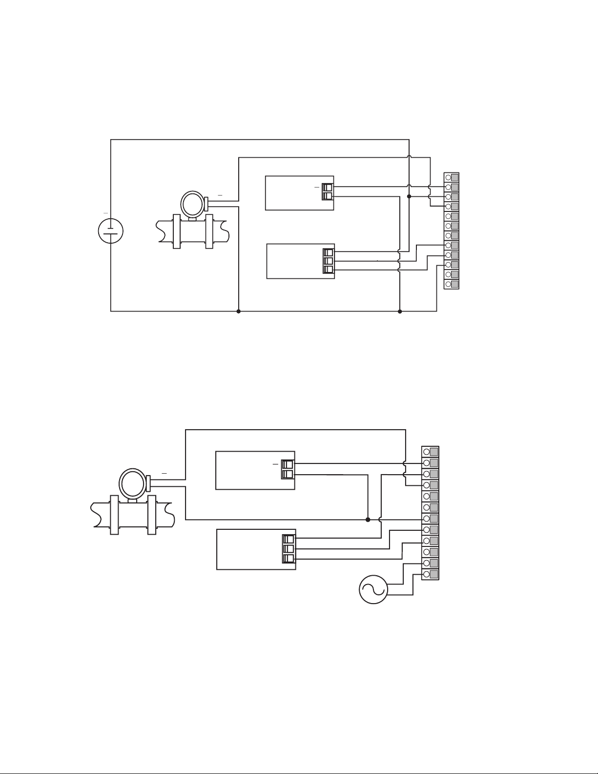
110 VAC ± 15% or 12 to 24VDC.
Current: maximum 300 mA DC or 8.0 VA at rated AC
volt age.
Output Power:
(AC pow ered units only) + 24VDC @
100mA regu lated ±5%
Temperature:
Operating: +41°F (5°C) to +130°F (+54°C).
Storage: -40°F (-40°C) to +200°F (93°C).
Memory
: EEPROM stores data for ten years if power
is lost.
Reset
:
Front Panel: resets dis played val ues and control out-
puts.
Remote: 4-30VDC positive edge, resets totalizer and
con trol out puts.
Output
:
Type: Open collector sinks 250mA from 30VDC when
ac tive.
Usage: rate alarm, total alarm, scaled pulse output
for remote totalizers.
Analog Out:
The full scale setting is pro gram mable
from the front panel. A sink ing driver gen er ates a cor-
re spond ing lin ear cur rent through the external devices.
The out put up dates with each update of the rate. Ac-
curacy is ±0.25% FS worst case. Compliance volt age
must be 3 to 30 VDC non in duc tive. (The unit can
provide the DC source as long as the drop across the
devices being driven does not ex ceed 21V).
Input:
Type: Linear 0-20mA, 4-20mA, 0-5V, 0-10V or 1-5V
se lectable from the front panel.
Input Impedance:
Current: 100Ω; Voltage: 115KΩ
Calibration:
The unit does all of the calibrations in ter -
nal ly. There are no potentiometers to adjust and the
unit never needs to be removed from the case.
Set Points:
Two control set points are provided. The
set point outputs can be as signed to rate or total or pulse
scaling. The unit comes stan dard with two open col-
lec tor control out puts. The out puts are pro gram mable
from 0.01 to 599.99 sec or latched until reset when
as signed to the total or pulse and a hys ter esis (alarm
range) when as signed to the rate.
Rate Display:
Updates 5 times per sec ond, Accurate
to 4.5 dig its.
Totalizer:
Integrates from the rate reading and ac cu -
mu lates up to 6 digits of total count. The time base (sec-
onds, minutes, hours or days) and totalize conversion
factor are fi eld pro gram mable from the front panel.
Programming
: Decimal points, Scal ing from 0 to
59999 units per se lected time base, set points, in put
type, security lock code, and as sign ing out puts are all
pro gram mable from the front panel.
Housing:
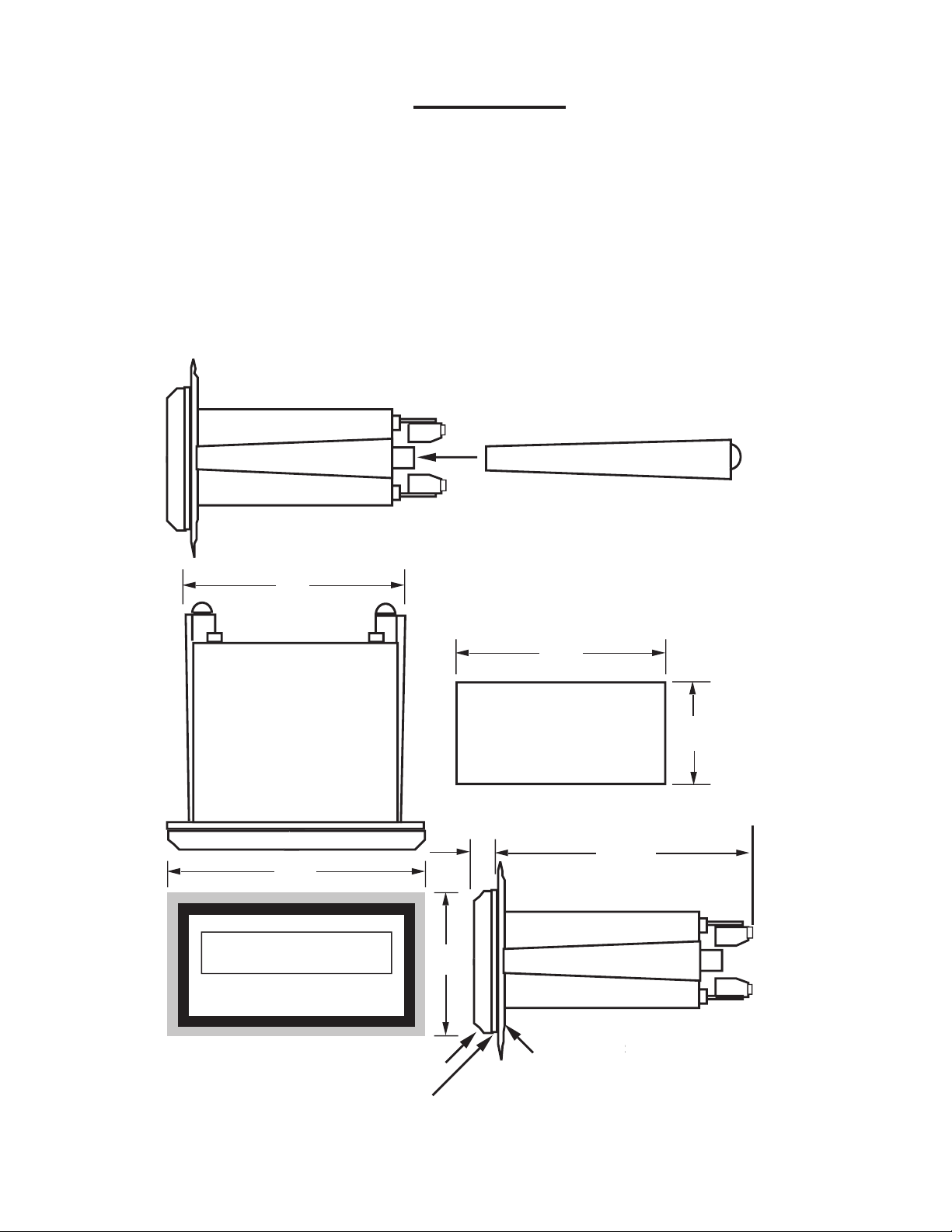
Standard 1/8 DIN, high im pact ABS plastic
case (NEMA 4/IP65 front panel).
Shipping Weight:
2 lbs.
Overvoltage Protection:
50 V
Overcurrent Protection:
50 mA
Resolution:
14.5 Bits
Accuracy:
RANGE
% FS ERROR
% FS ERROR
(worst case) (typical)
4-20 mA 0.1% .05%
0-10 VDC 0.2% 0.1%
0-5 VDC .25% .15%
1-5 VDC .25% .15%
Square Law: (above 5% of bottom range) 0.1%
(5V inputs .4%) Worst case over complete range: 2%
Temperature Stability:
Will not drift more than 20
parts per million per °C from 5°C to 54°C

2
MOUNTING
HOW TO MOUNT:
Slide the body of the unit through the rubber
gasket. Insert the unit into the panel. Slide the
brackets up the groove to press against the
back of the panel, as shown in "FIG. A". Insert
the screws into the rear of the brackets.
Tighten the screws evenly and alternately. A
panel less than 0.1" may distort if the clamps
are screwed too tightly. Do not over tighten!
A nor mal level of torque is required. Maximum
torque should be 3" pounds.
FIG. A
4.437
(1
12.7)
2.625
(66.68)
3.925
(99.7)
3.622
(92)
1.772
(45)
.587
4.245
(107.8)
BEZEL
GASKET
CUST
OMER P
ANEL
OMER PANELOMER P
Panel Thickness 0.062" (1.5)
to 0.187" (4.7) max.

3
WIRING
WIRING CONNECTIONS
AC / DC CONNECTIONS:
NOTE: Connect power only after other con-
nec tions are fi n ished. Do not touch the live AC
power ter mi nals. The unit has been de signed
with an isolated AC input, therefore polarity is
not a concern for the AC power. The chassis
is plastic, therefore earth ground is not used.
For DC operation, connect +DC to terminal 10
and -DC to terminal 3.
Although the unit is designed to be im mune
from line or RF interference, the unit is con-
trolled by a microprocessor and an elec tri cally
"noisy" environment could cause op er at ing
problems. The input power lines should not
be com mon to power lines for motors, pumps,
contactors, etc.
Four sources of noise can occur:
1) AC power line noise- If the unit cannot
be connected to an electrically clean power
source, an inductive load suppressing device
(MOV as GE#V130LA1 or Resistor Capacitor
as Paktron# .2uf/220 ohm @ 400V) can be
installed. Although locating the suppressor
across the AC supply at the unit should help,
best results are obtained by connecting the
suppressor across the leads of the "load" at
the device causing the spikes.
2) Input line noise- The noise is carried on
the input and DC ground lines. Make sure
the input wires are not run into the unit in a
bundle with power input lines. We recommend
using shielded cable. Connect the shield to
DC signal ground of the unit and "earth" at one
point in the circuit preferably at the DC ground
ter mi nal of the unit.
3) Output lines- The unit has two open col-
lec tor outputs. When these outputs are used
to run external relays or solenoids, spikes can
be generated upon activation. This noise can
spread through the instrument causing operat-
ing problems. If the source is a D.C. operated
device, a gen eral purpose diode (IN4004)
placed across the solenoid prevents electrical
noise spikes. Connect the cathode (banded
side) to the more positive side of the coil. If
the source is an A.C. operated device, use a
Resistor Ca pac i tor or MOV across the coil.
4) 24 VDC output supply- Noise can be gen-
er ated on the 24 VDC output supply if it is used
to drive inductive loads or if the current draw
exceeds 50mA. Insure that all inductive loads
have a diode (such as IN4004) across the coil
and that the current does not exceed 50mA.
REAR VIEW
1
2
3
4
5
6
7
8
9
10
10
11
12
12
13
13
14
14
15
15
15
15
17
17
18
18
1• Reset In
2• Analog Out (Sink)
3• Signal GRD (-DC)
4• (Current) +I in
5• (Voltage) +V in
6• Not Used
7• +24V Out
8• Preset B Collector
9• Preset A Collector
10• +DC In
11• AC Neutral
12• AC Line

4
TYPICAL WIRING HOOKUPS
DC Powered
AC Powered
1• Reset In
2• Analog Out (Sink)
3• Signal GRD (-DC)
4• (Current) +I in
5• (Voltage) +V in
6• Not Used
7• +24V Out
8• Preset B Collector
9• Preset A Collector
10• +DC In
11• AC Neutral
12• AC Line
1• Reset In
2• Analog Out (Sink)
3• Signal GRD (-DC)
4• (Current) +I in
5• (Voltage) +V in
6• Not Used
7• +24V Out
8• Preset B Collector
9• Preset A Collector
10• +DC In
11• AC Neutral
12• AC Line

5
The open collector outputs trig ger when the total or
rate (assignable; see pro gram ming step 2) equals the
corresponding Preset (A or B). When the output is as-
signed to "
pul
" (pulse output) the outputs trigger with
each count of the total (or multiples).
When the outputs are as signed to the "total", the op er a tor
can assign a duration of time (.01 to 599.99 sec.) that
the output will remain energized. If 0.00 is as signed,
the output will latch until reset. If output A is set at a
duration (other than 0.00), the totalizer will au tore cycle
when Preset A is reached. At this time, output B will
de-en er gize (if it was en er gized). Preset A is the fi nal
preset and should be set higher than Preset B, when
both outputs are as signed to the total. If output A is
set at a duration other than 0.00 and Preset A is set
less than Preset B, Preset B will be ignored (provided
that they are both as signed to total). The totalizer will
never au tore cycle at Preset B.
When the outputs are assigned to the "rate", the out-
puts can be assigned a hysteresis (alarm range). The
hysteresis is the number of units below the preset that
the output will remain energized. EXAMPLE: Preset set
@ 100; Hysteresis set @ 10. The output will energize
when the rate equals 100 and de-energize when the
rate falls below 90 (10 below Preset).
Select “
PuL
” (pulse output) to use the output for remote
totalizers. When set to “
PuL
”, a minimum duration in
seconds (0.00 to 599.99) can be assigned to the time
the output will remain energized and de-energized. If
0.00 is chosen the relay or open collector is disabled.
The pulse output follows the total and the relay or open
collector will output a “pulse” on every multiple of the
Preset Setpoint. (ie. Preset is set to 10. A pulse will be
generated for total values 10, 20, 30, 40, ... , etc).
NOTE:
If unit is setup to autorecycle then pulse output
should not be used.
OPEN COLLECTOR
2-Wire 4-20mA Transmitter
with Analog Output
4-Wire 4-20mA Transmitter
Flowmeter
(4-20mA
T
(4-20mA T(4-20mA
ransmitter)
Transmitter) T
VA
C
60/50 Hz
- +
- +
Power
Supply
•3 - Signal GND (-DC)
•4 - I In + (Current)
.
.
•1
1 -
A
C Neutral
•12 -
A
C Line
Flowmeter
(4-20mA
T
(4-20mA T(4-20mA
ransmitter)
Transmitter) T
-
+
VA
C
60/50 Hz
•3 - Signal GND (-DC)
•4 - I In + (Current)
.
•7 - +24V
Out
.
•1
1 -
A
C Neutral
•12 -
•3 - Signal GND (-DC) •3 - Signal GND (-DC)
A
C Line
2-Wire 4-20mA Transmitter with Multiple Devices
Flowmeter
(4-20mA
T
(4-20mA T(4-20mA
ransmitter)
Transmitter) T
VA
C
60/50 Hz
•2 -
Analog Out
•3 - Signal GND (-DC)
•4 - I In + (Current)
.
•7 - +24V
Out
.
•1
1 -
A
C Neutral
•12 -
A
C Line
+
-
-
+
Chart Recorder
Flowmeter
(4-20mA
T
(4-20mA T(4-20mA
ransmitter)
Transmitter) T
-
+
-
Chart Recorder
+
VA
C
60/50 Hz
•3 - Signal GND (-DC)
•4 - I In + (Current)
.
•7 - +24V
Out
.
•1
1 -
A
C Neutral
•12 -
•3 - Signal GND (-DC)
A
C Line
TYPICAL WIRING HOOKUPS (continued)

6
PROGRAMMING FLOWCHART
This symbol indicates any key.
Press this key to step through Menu choices
Press this key to enter displayed value.
NOTE:
SEVERAL PROGRAMMING SELECTIONS
WILL NOT APPEAR WITH "RATE ONLY"
& "TOTAL ONLY" UNITS
OPTIONS NOT ORDERED WILL NOT APPEAR
IN PROGRAM SELECTIONS
*
For best results, choose the highest res o lu tion pos si ble
when en ter ing the "set hi" and "lo cut" values.
Enter the proper rate decimal lo ca tion at the "rdec" prompt.

7
DEFINITIONS
input
- INPUT; This section of the program menu assigns the type of input the unit will be using (0-20 mA, 4-
20 mA, 0-5 V, 0-10 V, 1-5 V, Linear or square root extraction).
i 4-20
- I 4-20; This sets the unit for a current input of 4 to 20 mA.
i 0-20
- I 0-20; This sets the unit for a current input of 0 to 20 mA.
E 1-5
- E 1-5; This sets the unit for a voltage input of 1 to 5 volts.
E 0-5
- E 0-5; This sets the unit for a voltage input of 0 to 5 volts.
E 0-10
- E 0-10; This sets the unit for a voltage input of 0 to 10 volts.
LiNEAR
- LINEAR; This sets the unit for linear input.
S9RT
- SQUARE ROOT; This sets the unit for square root extraction.
RELAYS
- RELAYS; This section of the program menu sets the control output variables (open col lec tor).
A RATE
- OUTPUT A FOR RATE; This assigns the A output to the rate.
HYS A
- HYSTERESIS FOR OUTPUT A; This value is the number of units below Preset A that the output will
remain "ON". EXAMPLE: Preset A set at 100, Hys set at 10. Output A will activate (turn on) when the
rate equals 100; Output A will deactivate (turn off) when the rate falls below 90 (10 below Preset A)
A tot
- OUTPUT A FOR TOTAL; This assigns the A output to the totalizer.
A PuL
- Relay A assigned to pulse output.
DuR A
- OUTPUT A DURATION; This is the duration of time (.01 to 599.99 sec) that Output A will remain ener-
gized. If 0.00 is entered the output will latch until reset. If a value other than 0.00 is entered the unit will
autorecycle at Preset A.
B RATE
- OUTPUT B FOR RATE; This assigns the B output to the rate.
HYS B
- HYSTERESIS FOR OUTPUT B; Same as HYS A.
b tot
- OUTPUT B FOR TOTAL; This assigns the B output to the totalizer.
B PuL
- Relay B assigned to pulse output.
DuR B
- OUTPUT B DURATION; This is the duration of time (.01 to 599.99 sec) that Output B will remain ener-
gized. If 0.00 is entered the output will latch until reset.

8
loc
- LOCK; This section of the program menu sets up the lockout type and code.
LC ALL
- LOCK ALL; When this is selected the lockout will lock the program as well as the Presets and reset
button. The presets can be viewed but not changed.
lc pg
- LOCK PROGRAM; When this is selected the lockout will lock only the program. The Reset can be
activated and the presets can be viewed and changed.
code
- CODE; This is a 5-digit code which will be used to lock and unlock the front panel.
setup
- SETUP; This section of the program menu sets up the operating variables.
rdec
- RATE DECIMAL LOCATION; This allows the user to program a decimal point for the rate display.
SET Hi
- SET HIGH; This is the rate value for the highest input (5 or 10 Volts; 20 mA). (i.e. 20 mA = 500 lbs/
hr.)
lo cut
- LOW CUT-OFF; This is the lowest rate value to be recognized. All rate readings below this value will
assume the "set lo" value.
nor
- NORMALIZING FACTOR; This is an averaging factor (00.0 to 99.9). Higher settings provide more nor-
malizing (averaging) for a more stable display. Derived from the equation:
(OLD DATA x "NOR" + NEW DATA)
("NOR" + 1)
Sec
- SECONDS; This tells the unit that the High input value is entered in units per second.
NNiNs
- MINUTES; This tells the unit that the High input value is entered in units per minute.
hours
- HOURS; This tells the unit that the High input value is entered in units per hour.
days
- DAYS; This tells the unit that the High input value is entered in units per day.
tdec
- TOTALIZER DECIMAL LOCATION; This allows the user to enter a decimal for the totalizer display.
This decimal is not a dummy decimal and will scale the totalizer display accordingly. (i.e. if the tdec is set
in the tenths position (#####.#), 100 will be displayed as 100.0)
cfdec
- CONVERSION FACTOR DECIMAL; This menu allows users to select a decimal location for the con-
version factor
cfac
- CONVERSION FACTOR; This is a conversion divider factor that will be applied to convert from rate
volume units to total volume units (i.e. rate is gal/(units time) to ft
3
Conversion factor = 7.4805 (gal/ft
3
).

9
tmul
- TOTALIZER FACTOR; This factor divides the totalizer display by 1, 10, 100 or 1000.
opt
- OPTIONS; This section of the program menu is for setting up optional features (an a log out)
out hi
- OUT HIGH; The displayed rate value at which the unit will output 20 mA (2000 lbs./hr = 20 mA out).
PXXXXX
- P; This will appear in the 6th (furthest to the left) digit when viewing the Peak. The peak value is the
highest rate reading that the unit had displayed since the peak had been reset. The peak is not retained
in memory when power is lost.
uXXXXX
- U; This will appear in the 6th (furthest to the left) digit when viewing the Valley. The valley value
is the lowest rate reading that the unit had displayed since the valley had been reset. The valley is not
retained in memory when power is lost.
RXXXXX
- R; This will appear in the 6th (furthest to the left) digit when viewing the Rate.

10
PROGRAMMING
REMARKS
This section of the menu is used to
set up the type of signal the unit will
be receiving.
Press the PRGM key to step through
choices. Press the RST/ENTER key
to enter the displayed choice.
Press the PRGM key to toggle be tween
the choices and press the RST/ENTER
key to enter the desired choice.
NOTE:
Always choose LINEAR
DISPLAY
iNPuT
i 4-20, i 0-20
E 1-5, E 0-5
or
E 0-10
LiNEAR
or
S9RT
PRESS
FRONT PANEL OPERATIONS
Press to RESET
in op er at ing
mode; Press to
"ENTER" in pro-
gramming mode.
Press to view or
change Preset A
Press to view or
change Preset B
Press to al ter -
nately view Rate,
Total, Peak &
Valley.
Press to cycle
through PRO-
GRAM choices;
Press to step
through set up
choices in pro-
gram mode.
SET TING
INPUT
STEP
1
Press once to freeze
display. Press any
key to update display
normally.
Press rapidly
(3 times within 5
seconds) to "enter"
LOCK code for panel
lock.
PRGM
ENTER
PRGM
ENTER
PRGM

11
PRESS
DISPLAY
REMARKS
input
RELAYS
A RATE, A ToT
or
A PUL
(IF TOT or PUL
SE LECTED)
DuR A
(hit any key to view or
change ex ist ing dur A
value XX.X)
(IF RATE SELECTED)
HYS A
(hit any key to view or
change ex ist ing HyS A
value XXXXX)
B RATE
,
B ToT
or
b PUL
(IF TOT or PUL
SE LECTED)
DuR B
(IF RATE SELECTED)
HYS B
STEP
2
SET TING
RELAYS
NOTE:
If out puts are
not used, set
dur A
&
dur
B
at "0.00" to
pre vent the
counters from
re set ting at
the presets.
This section of the menu sets up the
open collector outputs.
Output A assigned to the rate,total or
pulse output. Press the PRGM key
to toggle be tween choices, press the
RST/ENTER key to enter the displayed
choice.
dur A = the duration of time (0.01 to
599.99 sec) that output A will remain on
or energized. When dur A is dis played,
hit any key to view or change dur A.
Press the RST/ENTER key to enter
dis played value. When dur A is set at
0.00,output A will latch until re set; when
dur A is set other than 0.00 the counter
will au tore cycle at Preset A.
Hys (hysteresis)= The number of units
below the preset that the output will
remain "ON". EXAMPLE: Preset set
@ 100; HyS set @ 10. Output will
activate (turn on) when rate = 100 and
turn off when rate falls below 90 (10
below preset).
Follow instructions for A RATE, A TOT
& A PUL
Follow instructions for dur A
Follow instructions for hys A
PRGM
PRGM
ENTER
ENTER
ENTER
ENTER
ENTER
PRGM
ENTER
PRGM

12
DISPLAY
REMARKS
STEP
3
SET TING
LOCK
This section of the menu is used to set
up the lockout type and code.
LC PG = Locks program but presets
are accessible.
LC ALL= Locks program & presets.
Press the PRGM button to toggle be-
tween choices; Press RST/ENTER to
enter displayed choice.
When CODE is displayed, press any
key to view existing lock code. To
change the code press the key under
each digit to be changed. Press RST/
ENTER to enter displayed value.
input
RELAYS
LoC
LC PG
or
LC ALL
or LC ALLor
CoDE
Press any key to view
or change the lock
code
PRESS
This section of the menu is used to set
up important operating variables.
RDEC= rate decimal location; Press
the key under the digit with the desired
lo ca tion. Press the "E" key if a decimal
is not desired. Press RST/ENTER to
enter the dis played location.
SET HI= Rate value for the highest
input (5 or 10V; 20mA).(i.e. 20mA =
500 lbs/hr.). Key in the desired high
value and press RST/ENTER to enter
dis played value.
input
RELAYS
LoC
SETuP
rDEC
SET Hi
Press any key to view
or change existing
value
CONTINUED ON NEXT PAGE
STEP
4
SET TING
SETUP
PRGM
PRGM
ENTER
ENTER
ENTER
PRGM
PRGM
PRGM
PRGM
PRGM
ENTER
PRGM

13
REMARKS
DISPLAY
PRESS
LO CUT= Low cut-off; Lowest rate
value to be recognized. All rate read-
ings be low the "cutoff" will assume
the "set lo" value. Key in the de sired
value and press RST/ENTER to enter
dis played value.
NOR= Normalizing (averaging) fac-
tor (00.0 to 99.9); Key in the desired
value and press RST/ENTER to enter
dis played value. Higher settings pro-
vide more nor mal iz ing (averaging) for
a more stable display.
This section tells the unit that the high
setting is entered in units per Sec-
ond, Minute, Hour or Day. Press the
PRGM key to step through choices.
Press RST/ENTER to enter displayed
choice.
TDEC= Totalizer Decimal; Press the
arrow keys to enter in the de sired
to tal iz er decimal. Press RST/ENTER
to enter displayed choice. Entering
a decimal will add resolution to the
total. (i.e. tdec=#####.#; 100 will be
dis played as 100.0)
CFDEC= Conversion Factor Decimal;
Press the ar row keys to enter in the
de sired conversion factor decimal.
Press RST/EN TER to enter displayed
choice.
CFAC= Conversion Factor; The con-
ver sion factor allows you to convert
rate to total volume units.
TMUL= Totalizer Multiplier; This fac tor
al lows you to divide the totalizer by 1,
10, 100, 1000
Press the PRGM key to step to the
desired factor. Press RST/ENTER to
enter displayed choice.
Lo CuT
Press any key to view
or change existing
value
NoR
Press any key to view
or change existing
value
sec, NNiNS, HouRS
or
days
or daysor
tdec
CFdec
CFac
tmul
Press any key to view
or change existing
value
1
,
10
,
100
or
1000
STEP
4
CONT...
SET TING
SETUP
ENTER
ENTER
PRGM
ENTER
ENTER
ENTER
ENTER
ENTER
ENTER
PRGM
NOTE:
See Appendix i
(PG17) for a chart
containing com-
mon conversion
factors

14
REMARKS
DISPLAY
PRESS
This section of the menu is for setting
up the variables for any options which
were ordered (Analog out or Serial
communications).
OUT HI= The rate value represented by
the 20 mA end of the 4-20 mA output.
Key in the desired value and press RST/
ENTER to enter dis played value.
Press
PRGM to recycle through list choices.
STEP
5
SETTING
OPTIONS
THE PROGRAM SETUP IS COMPLETE! YOU ARE NOW READY TO SET THE PRE SETS.
input
RELAYS
LoC
SETuP
oPT
ouT Hi
Press any key to view
or change existing
value
PRGM
PRGM
PRGM
PRGM
ENTER
PRGM

15
REMARKS
DISPLAY
PRESS
SETTING THE PRESETS & PANEL LOCK
SETTING
THE
PRESETS
PRE A
Press any key to view
or change existing
value
PRE B
Press any key to view
or change existing
value
CoDE
Press any key to enter
the 5-digit lock code.
LoC
or
UN LoC
PRE A = Preset A (Final Preset); The
set point at which output A will trigger.
If the displayed value is not the de sired
preset, press the key(s) under the digit
to be changed.
PRE B = Preset B (Prewarn); The set
point at which output B will trigger. If
the dis played value is not the de sired
preset, press the key(s) under the digit
to be changed.
Key in the lock code (see pro gram ming
step 3) by pressing the keys under the
digits to be changed. Each time a key
is pressed the digit will increment one.
Press the RST/EN TER key to enter the
displayed code.
After the code is entered the unit will
display LOC (unit is locked) or UN LOC
(unit is un-locked). This message will
be displayed for approximately 3 sec-
onds before the unit returns to the run
mode. If an invalid code is entered, no
message is displayed; try again.
Press LOCK 3 times within 5 seconds
(If LOCK is pressed once, unit freezes display)
SETTING
THE
LOCK
STATUS
PRE
A
PRE
B
LOCK
LOCK
LOCK
ENTER

16
TROUBLESHOOTING GUIDE
PROBLEM
POSSIBLE CAUSES
SOLUTIONS
Power is applied to unit but the
display does not light.
Unit works but occasionally
the display freezes or skips
counts.
Input signal is connected but
the unit does not totalize or
rate.
Display reading is inaccu-
rate.
Ratemeter works properly but
totalizer is incorrect.
1. AC or DC power wiring is
incorrect.
1. Line noise is effecting the
processor due to a current
spike or surge.
1. Input wiring is incorrect
2. High scaling or Low cutoff
settings are in cor rect.
3. Transmitting device is de-
fec tive.
4. Unit is defective.
1. Input wiring is incorrect.
1. Time base is incorrect.
2. Conversion factor is in-
cor rect
3. Total multiplier is incorrect
1. Recheck power wiring.
1. Use a different power sup-
ply or install a surge sup-
pres sor.
1. Recheck input wiring.
2. Recheck high scaling and
low cutoffsettings.
3. Replace transmitting de-
vice.
4. To confi rm set meter for 0-
10V input, low @ 0; high @
10. Apply a 0-10V signal
to the voltage input (pin 5).
When viewing the rate the
meter should display the
voltage value that is ap-
plied. If not call factory for
an RMA#.
1. Be sure that voltage sig nals
are connected to volt age
in put (pin 5) and cur rent
signals are connected to
current input (pin 4).
1. Recheck time base setting
in setup section of the pro-
gram menu.
2. Recheck conversion factor
settings.
3. Recheck total multiplier fac-
tor settings.
IF YOU HAVE ANY OTHER PROBLEMS, PLEASE CALL THE FACTORY.
Table of contents
Other KEPCO Measuring Instrument manuals

KEPCO
KEPCO INTELLECT-69 Series Manual

KEPCO
KEPCO SUPERtrol-1LE User manual

KEPCO
KEPCO KEPtrol F/C User manual

KEPCO
KEPCO BATCHtrol II Wiring diagram

KEPCO
KEPCO 520 Series User manual

KEPCO
KEPCO 520K Series User manual

KEPCO
KEPCO MINI-BATCHER MB2 Manual

KEPCO
KEPCO LEVELtrol-II User manual

KEPCO
KEPCO MS735 Series User manual

KEPCO
KEPCO 528 Series User manual