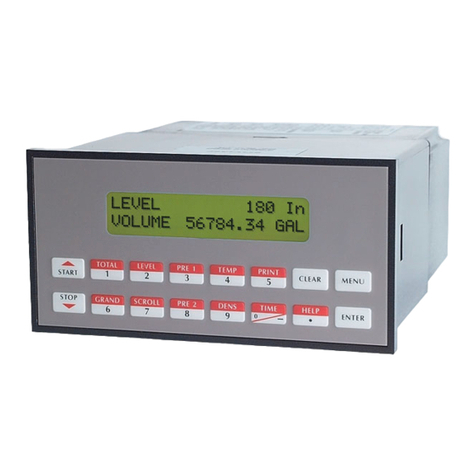
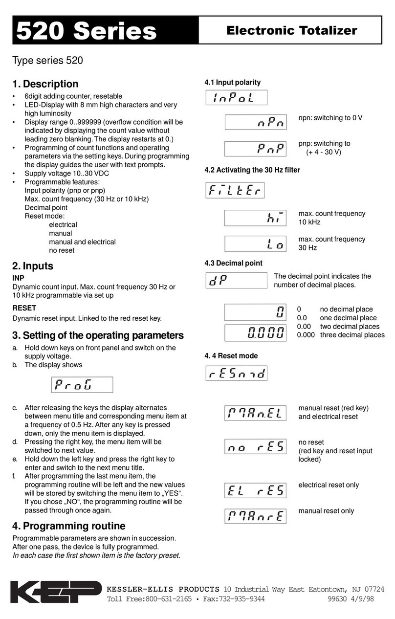
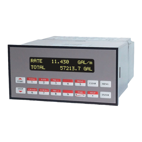
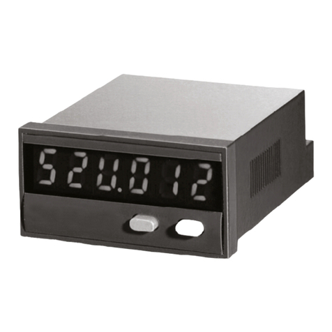
KEPCO KEPtrol F/C User manual

99300 11/10/09
Description
The KEPtrol F/C is designed to measure the net flow of boiler fuel. Separate K-Factors can be entered
for A and B inputs. Two SPDT relay alarm outputs are standard. A scaled pulse output is standard for
interfacing with remote devices. An analog output option is also available to interface with strip chart
recorders.
Features
❑Flow (A) - Flow (B) Displays Net Rate & Net Total
❑ Pulse Input to 10 kHz Count Frequency
❑Separate K-Factors for A & B Inputs
❑Set Point Alarms
❑NEMA 4X / IP65 Front Panel
Application
The unit is normally used to measure the net flow of boiler fuel. The display may be toggled between net
rate, and net total. Two programmable K-factors make keying-in engineering units easy. The unit accepts
pulse or contact closures and provides two separate preset controls.
KEPtrol F/C
Kessler-Ellis Products Co.
C/FlortPEK C/FlortPEK C/FlortPEK C/FlortPEK
KEPtrol F/C
Net Ratemeter & Net Totalizer
KESSLER-ELLIS PRODUCTS
10 Industrial Way East
Eatontown, NJ 07724
800-631-2165 • 732-935-1320
Fax 732-935-9344
http://www.kep.com

!
SAFETY INSTRUCTIONS
The following instructions must be observed.
• This instrument was designed and is checked in accordance with
regulations in force EN 60950 (“Safety of information technology
equipment, including electrical business equipment”).
A hazardous situation may occur if this instrument is not used for its
intended purpose or is used incorrectly. Please note operating
instructions provided in this manual.
• The instrument must be installed, operated and maintained by
personnel who have been properly trained. Personnel must read and
understand this manual prior to installation and operation of the
instrument.
• The manufacturer assumes no liability for damage caused by incorrect
use of the instrument or for modifications or changes made to the
instrument.
Technical Improvements
• The manufacturer reserves the right to modify technical data without
prior notice.

SECTION 1 INTRODUCTION
1-1 General Description ................................... 1
1-2 Typical Application ..................................... 1
1-3 Principles of Operation ............................... 1
1-4 Specifications .............................................. 2
Full Size Panel Cutout Template ..................... 4
SECTION 2 INSTALLATION
2-1 Receipt of Equipment ................................ 5
2-2 Return Shipment ....................................... 5
2-3 Panel Mounting ......................................... 5
2-4 Electrical Connections ............................... 5
2-5 Wiring Connections and Diagrams ........... 5
SECTION 3 OPERATION
3-1 How to Program .......................................... 6
3-2 Frequently Asked Questions About
Setting Up The Unit .................................. 7
3-3 Setup Procedure For The Unit
SETTING PRESET A..................................... 7
SETTING PRESET B ..................................... 8
MENU ITEM 1 DEV TYP............................. 8
MENU ITEM 2 LOCKOUT........................... 10
MENU ITEM 3 OUTCARD............................ 11
MENU ITEM 4 ALG OUT............................ 11
MENU ITEM 4 OUTFREQ........................... 12
MENU ITEM 6 RELAY................................. 13
3-4 Run Mode
3-4.1 The Display .............................................. 13
3-4.2 Reseting (Clearing) the Totalizer............ 13
3-4.3 Locking the Unit ...................................... 14
3-4.4 Operation ................................................. 14
3-5 Internal Operation
Digital Inputs and Computations .................... 15
SECTION 4 INPUTS
4-1 Digital Pulse Inputs.................................... 15
4-1.1 Input 3A ................................................... 16
4-1.2 Input 3B ................................................... 16
4-1.3 Reset Input ............................................... 16
4-2 DC Power InputS ........................................ 16
4-3 AC Power Inputs ......................................... 16
SECTION 5 OUTPUTS
5-1 Control Outputs ......................................... 17
5-1.1 SPDT Relay Version ................................ 17
5-1.2 Open Collector Version ............................ 17
5-2 Scaled Pulse Output ................................... 17
5-3 Optional Analog Output ............................. 18
5-4 Optional RS232 / RS422
Serial Communications .................................... 18
SECTION 6 TROUBLE SHOOTING AND
MAINTENANCE GUIDE
6-1 Warning Messages ..................................... 18
6-1.1 RFFFFFFF......................................................... 18
6-1.2 LOCK ON ................................................ 18
6-2 Troubleshooting ......................................... 18
6-2.1 General ............................................................... 18
6-2.2 Problems ................................................... 19
6-3 Removing the Case ..................................... 19
6-3.1Input Card Modification .......................... 20
6-3.2 Serial Communications
Interface Installation ........................................ 20
6-4 Maintenance................................................ 20
SECTION 7 CALCULATING THE K FACTORS
7-1 General ........................................................ 20
7-1.1 What is a K Factor? ................................ 20
7-2 Calculating the K Factors. ......................... 20
7-2.1 Calculating the K Factor for
Digital Pulse Inputs .......................................... 21
7-2.2 Digital K Factor Formulas ...................... 21
SECTION 8 SERIAL COMMUNICATIONS
8-0 Outcard RS232/RS422
Serial/Strobe Interface ...................................... 22
8-1 Unit Code .................................................... 22
8-2 Baud Rate.................................................... 22
8-3 Parity ........................................................... 22
8-4 RS232 Electrical Requirements ................. 22
8-5 RS232 Card Wiring ..................................... 23
8-5.1 Wiring Diagram RS232 / Strobe ............. 23
8-5.2 RS232 Wiring Notes ............................... 23
8-6 RS422 Electrical Requirements ................. 23
8-7 RS422 Card Wiring ..................................... 24
8-7.1 Wiring Diagram RS422 / Strobe ............. 24
8-7.2 RS422 Wiring Notes ................................ 24
8-8 Strobe Input Electrical Requirements ....... 24
8-8.1 Strobe Input Levels ................................. 24
8-9 Strobe Wiring .............................................. 25
8-9.1 Strobe Wiring (RS232) ............................. 25
8-9.2 Strobe Wiring (RS422) ............................. 25
8-10 Serial Interface Operation ....................... 25
8-10.1 Serial Communications Timing ............ 26
8-10.2 RS232/RS422
Serial Input Codes ............................................ 26
8-10.3 RS232/RS422
Serial Input Examples ...................................... 26
8-11 Strobe Address Operation ........................ 27
8-11.1 Strobe Input Codes ................................ 27
CONCLUSION ........................................................... 27
DECODING PART NUMBER ................................... 27
WARRANTY ............................................................... 27
WORKSHEET.............................................................28
PROGRAMMING FLOW CHART.............................. 29
TABLE OF CONTENTS

THIS PAGE IS BLANK

Page 1
SECTION 1 INTRODUCTION
1-1 General Description
The two-setpoint, electronic, controller, is a
microprocessor-based,panel-mounted, instrument.
It is designed to be used in conjunction with
primary flow sensors which have pulse or contact
closure output. The main function of the unit is
to provide net rate of flow, net totalization and
control of process batch size and/or flow.
1-2 Typical Application
The above application is a boiler fuel consumption
monitor. The Unit receives pulses from Feed and
Recirculating flowmeters for total and for rate.
Each pulse input is scaled by separate K Factors.
Pulses from B are subtracted from A to give a net
rate and total. The Analog output is directed to a
strip chart recorder which gives a hardcopy of
the net rate. Setpoint A alarms if net rate value
is exceeded. Setpoint B illuminates light when
set amount of fuel is consumed. Through the
serial communications, a computer keeps a record
of the daily events.
1-3 Principles of Operation
Presets
The user may assign the two preset setpoints to
any of the following: "A" rate input, "B" rate
input, the net rate or the net total. The presets
are accessed by pressing the A or B buttons on
the front panel. The 10A SPDT relays are
activated when the display meets or exceeds the
preset values.
Ratemeter
Accurate to 5 1/2 digits (±1 display digit). The
ratemeter can be programmed to accept almost
any number of pulses per unit of measurement by
using the proper K Factors for the "A" and "B"
inputs. It can sample from 2 to 24 seconds
maximum, and auto range up to 6 digits of
significant information. The ratemeter with both
K Factors at 1, displays the net rate of pulses per
second. Simply dial in the proper K Factors to
display in minutes, hours or other units of
measurement. The unit can be made to display
the net rate and the net total. Press the C button,
while the unit is displaying the net total, to
display the net rate; 'R' is displayed on the left
side of the display.
K Factors
The K Factors are used to convert the input
pulses into workable units. The 8 digit K Factors
are dividers with a range of 0.0001001 to
99999999 (the decimal point may be keyed into
any position). Separate K Factors may be entered
into the count and rate sections of The Unit.
Thus, you may total in gallons and display rate in
liters per hour. The maximum factored count
speed is 9.98 KHz. The maximum factored rate is
7 digits.
Counter
The maximum count is 99999999. All counts are
accumulated even if simultaneous pulses occur.
In the setup mode choose "A-B" (Subtract input B
from input A) or "A+B" (Adds both inputs
together). Activating the CLR button while in
the run mode, resets the Net Total counter. Net
totals less than zero are displayed with a negative
sign on the left.
Fuel Feed
Flowmeter Fuel Recirculate
Flowmeter
Pulse Output A Pulse Output B
Low Fuel Indicator
Rate Alarm
4-20 mA Out to
Strip Chart Recorder
RS232 to
Computer

Page 2
1-3 Principles of Operation (continued)
Lockout
Unauthorized front panel changes can be
prevented by entering a user selected, four digit
code, in the "Lockout" mode. The status of the
unit can be observed but "LOCK ON" appears if
changes are attempted. Entering the code again
returns the unit to "LOCK OFF" status.
Scaled Pulse Output
The scaled pulse output corresponds to NET total.
The unit gives one pulse out for each positive
factored count. The output pulse duration is
selectable by choosing one of the following
frequencies: 20000, 2000, 200, 10. (see table
below)
Speed (Hz) 10 200 2000 200000
Min. ON/OFF (mSec) 47.5 2.0 0.2 0.013
NOTE: In the event where the unit counts down
(Input A signal momentarily lost), there will not
be any pulses present at Terminal 2. The output
pulses will be stored in an internal buffer. The
buffer will hold up to 10,000 pulses. The display
will show "DATALOST" if this buffer is filled.
When normal operation resumes and the counter
begins to count up, the output will remain OFF
until the amount of "up" counts equals the
amount of pulses in the buffer.
Analog Output (Optional)
The Analog Output option is controlled by an
Open Collector transistor; it gives a 4 to 20mA (or
0-20mA) output which corresponds to predefined
net rate or net total readings. In the Setup mode
the user is prompted to set the low and high (4
to 20 mA) values and also decide if the analog
signal will correspond to the ratemeter or
totalizer. The output for values below the "low"
setting will be 4 mA (0 mA). Compliance voltage
3 to 24 VDC. The output for values above the
"high" setting will be 20 mA.
A sinking driver generates a linear current across
the user's external device (such as a strip chart
recorder, PLC, computer, external meter, etc).
The Unit can supply the 24 VDC to power the
current loop. (Connect pin 15 to 13, Pin 16 is now
+24 VDC with respect to pin 12.) Connect Pin 16
to the + DC side of the external device and
connect Pin 3 to -DC side of the external device.
Outcard (Optional)
RS232 or RS422 serial two-way communication is
available. Up to 15 units can be linked together
in parallel and addressed separately to transmit
unit status or accept new set points in the
standard ASCII format. Baud rates of 300, 600,
1200, 2400, 4800 or 9600 as well as choice of odd,
even, space, or mark parity can be selected by
keypad control. Special OptoMux® compatible
RS422M is also available (See Section 8-12).
1-4 Specifications
Housing:
High impact plastic case with NEMA 4X front
panel.
Dimensions:
Reference Figure 1-1
Display:
8 Digit, 0.55" High, 15 Segment, Red Orange,
LED.
Input Power:
A: 110 VAC ±15% or 12 to 27 VDC
B: 220 VAC ±15% or 12 to 27 VDC
Current:
Maximum 280 mA DC or 5.3 VA at rated AC
voltage.
Output Power:
(On AC powered units only): +12 VDC at 100 mA.
Separate Isolated 12 VDC at 100 mA to allow ±12
VDC or +24 VDC, regulated ±5% worst case.
Temperature:
Operating: +32°F (0°C) to +130 °F (+54°C)
Storage: -40°F (-40°C) to +200 °F (+93°C)

Page 3
1-4 Specifications (continued)
Memory:
EEPROM stores all program and count data
for a minimum of 10 years if power is lost.
Reset:
Front push button: "CLR" resets displayed
number and control output.
Remote Input (Terminal 5): Open or 0 to 1
VDC (low), 3 to 30 VDC (high), 10K ohm
input impedance to ground. Minimum pulse
on / off time 5 msec., positive edge triggered.
Accuracy over full temperature range:
Digital - 100% (within specified voltage
ranges)
Pulse Inputs:
3A: Standard. High impedance pulse input.
Open or 0 to 1 VDC (low), 3 to 30 VDC (high),
10K ohm input impedance. 9980 Hz
maximum speed (min. on / off 50.1 usec).
3B: Same as 3A except 4.7 K ohm pull up
resistor to +5 VDC with respect to Terminal
12.
Scaled Pulse Output (Terminal 2):
NPN Open Collector; Sinks max. 100mA from
a maximum of 30 VDC to a maximum 1 VDC.
Analog output:
4-20 mA (or 0-20 mA)
Sinking, (NPN transistor), Open Collector
Compliance voltage: 3 - 24 VDC, noninductive
Accuracy: ±100 uA worst case
Update Rate:
Tracking Rate: follows displayed rate.
Tracking Total: approximately 5 updates
per second
Control Outputs (Each of two outputs):
1. NPN Transistor Version: (Optional)
Open Collector sinks maximum of 250 mA at 30
VDC when active
Note: When relays are used, 10 VDC is
provided at transistor outputs through the
relay coils. If current greater than 2 mA is
drawn, the relay will remain energized.
Applying greater than 10 VDC may destroy the
unit. The transistor will sink 100 mA in the
"ON" state with relays installed.
2. SPDT Relay Version: (Standard)
Contact rating: 10 A 120/240 VAC or 28
VDC.

Page 4
Figure 1-1
12345678901234567890123456789012123
1
234567890123456789012345678901212
3
1
234567890123456789012345678901212
3
1
234567890123456789012345678901212
3
1
234567890123456789012345678901212
3
1
234567890123456789012345678901212
3
1
234567890123456789012345678901212
3
1
234567890123456789012345678901212
3
1
234567890123456789012345678901212
3
1
234567890123456789012345678901212
3
1
234567890123456789012345678901212
3
1
234567890123456789012345678901212
3
1
234567890123456789012345678901212
3
1
234567890123456789012345678901212
3
1
234567890123456789012345678901212
3
1
234567890123456789012345678901212
3
1
234567890123456789012345678901212
3
1
234567890123456789012345678901212
3
1
234567890123456789012345678901212
3
1
234567890123456789012345678901212
3
1
234567890123456789012345678901212
3
1
234567890123456789012345678901212
3
1
234567890123456789012345678901212
3
1
234567890123456789012345678901212
3
1
234567890123456789012345678901212
3
1
234567890123456789012345678901212
3
1
234567890123456789012345678901212
3
1
234567890123456789012345678901212
3
1
234567890123456789012345678901212
3
1
234567890123456789012345678901212
3
1
234567890123456789012345678901212
3
1
234567890123456789012345678901212
3
1
234567890123456789012345678901212
3
1
234567890123456789012345678901212
3
1
234567890123456789012345678901212
3
1
234567890123456789012345678901212
3
1
234567890123456789012345678901212
3
1
234567890123456789012345678901212
3
1
234567890123456789012345678901212
3
1
234567890123456789012345678901212
3
1
234567890123456789012345678901212
3
1
234567890123456789012345678901212
3
1
234567890123456789012345678901212
3
1
234567890123456789012345678901212
3
1
234567890123456789012345678901212
3
1
234567890123456789012345678901212
3
1
234567890123456789012345678901212
3
1
234567890123456789012345678901212
3
1
234567890123456789012345678901212
3
1
234567890123456789012345678901212
3
1
234567890123456789012345678901212
3
1
234567890123456789012345678901212
3
1
234567890123456789012345678901212
3
1
234567890123456789012345678901212
3
1
234567890123456789012345678901212
3
1
234567890123456789012345678901212
3
1
234567890123456789012345678901212
3
1
234567890123456789012345678901212
3
1
234567890123456789012345678901212
3
1
234567890123456789012345678901212
3
1
234567890123456789012345678901212
3
1
234567890123456789012345678901212
3
1
234567890123456789012345678901212
3
1
234567890123456789012345678901212
3
1
234567890123456789012345678901212
3
1
234567890123456789012345678901212
3
1
234567890123456789012345678901212
3
1
234567890123456789012345678901212
3
1
234567890123456789012345678901212
3
1
234567890123456789012345678901212
3
1
234567890123456789012345678901212
3
1
234567890123456789012345678901212
3
1
234567890123456789012345678901212
3
1
234567890123456789012345678901212
3
1
234567890123456789012345678901212
3
1
234567890123456789012345678901212
3
1
234567890123456789012345678901212
3
1
234567890123456789012345678901212
3
1
234567890123456789012345678901212
3
1
234567890123456789012345678901212
3
1
234567890123456789012345678901212
3
1
234567890123456789012345678901212
3
1
234567890123456789012345678901212
3
1
234567890123456789012345678901212
3
1
234567890123456789012345678901212
3
1
234567890123456789012345678901212
3
1
234567890123456789012345678901212
3
1
234567890123456789012345678901212
3
1
234567890123456789012345678901212
3
1
234567890123456789012345678901212
3
1
234567890123456789012345678901212
3
1
234567890123456789012345678901212
3
1
234567890123456789012345678901212
3
1
234567890123456789012345678901212
3
1
234567890123456789012345678901212
3
1
234567890123456789012345678901212
3
1
234567890123456789012345678901212
3
1
234567890123456789012345678901212
3
1
234567890123456789012345678901212
3
1
234567890123456789012345678901212
3
12345678901234567890123456789012123
Full Size Panel Cutout
Template

Page 5
SECTION 2 INSTALLATION
2-1 Receipt of Equipment
When the equipment is received, the outside
packing case should be checked for damage
incurred during shipment. If the packing case is
damaged, the local carrier should be notified at
once regarding his liability. A report should be
submitted to the distributor.
Remove the Installation and Operation
Instructions. Carefully remove the equipment
from the packing case and inspect for damaged or
missing parts.
2-2 Return Shipment
Do not return assembly or part without a Return
Material Authorization. The RMA is obtained by
calling your local authorized distributor.
2-3 Panel Mounting
The controller should be located in an area with a
clean, dry atmosphere which is relatively free of
shock and vibration. The Unit is installed in a
7.365" (187 mm) wide by 2.495" (63.4 mm) high
panel cutout. To mount the controller proceed as
follows:
a. Prepare the panel opening.
b. Slip the gasket (provided) over the rear of the
counter case and slide it forward until it
engages the inner surface of the front bezel.
c. Install the screws (provided) in the mounting
brackets and insert in the holes located on both
sides of The Unit.
d. Tighten the screws firmly to attach the
counter bezel to the panel.
2-4 Electrical Connections (Reference Figures 2-1
to 2-3)
All connections are completed at terminal blocks
located at the rear of the case. Make sure all
power is disconnected before making any
electrical connections. In cases where cables are
situated in areas with heavy electrical
fields, shielding is required for maximum
noise immunity. One end of the shielding
should be connected to earth ground. Relays
or inductive coils connected to or located in
the immediate area should be arc suppressed
with appropriate diodes, MOV's, or resistor
capacitor networks.
2-5 Wiring Connections and Diagrams
1- Not Used
2- Scaled Pulse Output (Open Collector)
3- Input B
4- Input A
5- Reset Input
6- Not Used
7- Not Used
8- Not Used
9- Not Used
10- Analog Output (Sink)
11- Ground (-DC)
12- Ground (-DC)
13- (+) 12 VDC Output
14- (+) DC Power In
15- Isolated -12 Volts
16- Isolated +12 Volts
17- AC In
18- AC In
19- Preset B Transistor O.C.
20- Preset A Transistor O.C.
R1- N.O
R2- N.C. Preset A
R3- Common
R4- N.O
R5- N.C. Preset B
R6- Common
Figure 2-1 Terminal Block Connections
123
123
123
123
123
123
123
123
123
123
123
123
123
123
123
123
123
123
123
123
123
123
123
123
123
123
123
123
123
123
123
123
123
123
123
123
123
123
123
123
123
123
123
123
123
123
123
123
123
123
123
123
123
123
123
123
123
123
123
123
123
123
123
123
123
123
123
123
123
123
123
123
123
123
123
123

Page 6
2-5 Wiring Connections and Diagrams (continued)
Figure 2-3 24 Volt DC Output Wiring Connec-
tions
Figure 2-2 Typical Digital Input Wiring
Connections
SECTION 3 OPERATION
3-1 How to Program
The initial programming of the unit is
accomplished by first depressing the MENU
button. After pressing the MENU button once,
the display will read DEV TYP. To cycle to the
next control parameter option, merely press the
MENU button and LOCKOUT will appear on the
display. If the user does not wish to choose this
section of the menu, depress MENU button again
and the next control or parameter will appear.
Selection of all MENU control parameters is
accomplished through the routine described for
DEV TYP.
The following is the sequence for entering a
Preset quantity.
1. Depress the PRE A A button once. The
display will read PRESET. After a one second
pause the display will show the preset number.
2. The display will flash indicating that you are
not in the Run Mode and not displaying the
current rate or total.
3. If the displayed setpoint is satisfactory, depress
the ENT button. This value will be entered into
memory. Simultaneously, the unit will return to
the Run Mode.
4. To change the preset value, depress the CLR
button and enter a new number. Example:
Suppose "250" is the new batch size. Press 2 ,
then 5 , then 0 . When the display holds the
desired value, depress the ENT button. The
new set point will be stored in memory and
simultaneously The Unit will return to the Run
Mode.

Page 7
3-2 Frequently Asked Questions About
Setting Up The Unit
Q. Is there any way to backspace if the wrong
button is hit by accident?
A. No, you can depress the CLR button and
start entering the number all over again. Or
press ENT repeatedly until back in the Run
mode and start over again from there.
Q. Is there any way to put a decimal point in a
number such as the K Factor?
A. Yes, simply press the D button after the
digit that you would like the decimal point. It
will appear to the right of the digit.
Q. Is there any way to enter a negative number
for one of the Presets or K Factors?
A. No, negative values are not allowed.
Q. Is there any way to ruin the unit or
completely erase it by entering a bad number?
A. No, if a number or entry is not valid, the unit
will ignore it or flash an error message.
Q. If the unit does not have serial
communications or analog output, does the
OUTCARD or ALG OUT sections of the menu
still have to be set up?
A. No, there are default settings from the factory
already in the unit. No setup of these menu
items is necessary for normal operation.
Q. If CLR is not pressed, numbers can still be
written over the Presets or K Factors. Will these
numbers be accepted if the ENT button is pushed?
A. No, in order for a Preset or K Factor to be
changed, the old number must be cleared out first
by depressing the
CLR button. Otherwise, new numbers will be
added to the end of the previous number.
Note: Sometimes the setup of the unit may seem
confusing. Worksheets have been provided with the
unit to make the setup easy. Most questions can be
answered simply by reviewing the manual. If you
still have problems or questions, please call your
local Distributor.
3-3 Setup Procedure For The Unit
SETTING PRESET A
PRESS DISPLAY
A PRESET A
PRE A Button.
Enters Preset Routine. Flashing PRESET A
number.
CLR 0 Flashes.
Clears out existing PRESET A.
1 2 3 4 1234 PRESET A
Flashes.
Sample Preset.
ENT Last count, unit now in run
Store new Preset. mode.
Preset A is Set.

Page 8
3-3 Setup Procedure For The Unit (continued)
SETTING PRESET B
PRESS DISPLAY
B PRESET B
PRE B Button.
Enters Preset Routine. Flashing PRESET B
number.
CLR 0 Flashes.
Clears out existing PRESET B.
1 2 3 4 1234 PRESET B
Flashes.
Sample Preset.
ENT Last count, unit now in run
Store new Preset. mode.
Preset B is Set.
MENU ITEM 1 DEV TYP
This menu item is used to set up the ratemeter and
totalizers. Please refer to the K Factor worksheets
(Section 7) or other notes you may have prepared.
Setting the Ratemeter.
PRESS DISPLAY
D Menu Button DEV TYP ↓
ENT RT ↓CNT ↓
Enters routine to program the Ratemeter or
Counter.
B K FACT A
This selects the Ratemeter portion of the unit.
K FACT A flashes then shows the current rate K
Factor for input A.
CLR 0 Flashes.
Clears out existing A K FACTOR.
1 2 D 0 5 6 12.056 Flashes.
Sample K Factor, or enter calculated value from
notes or worksheet.
ENT K FACT B
We are still in the Ratemeter portion of the unit.
K FACT B flashes then shows the current rate K
Factor for input B.
CLR 0 Flashes.
Clears out existing B K FACTOR.
7 6 D 2 8 76.28 Flashes.
Sample K Factor, or enter calculated value from
notes or worksheet.
ENT WEIGHT #.#
Store new K Factor.
The weight is a multiplier assigned to the old rate
that is averaged with the new sampled rate to
prevent erratic change. A 0.0 setting shows the
new rate immediately. A 9.9 setting averages the
new sampled rate with 9.9 times of old displayed
rate. (See section 3-5 Internal Operation.)
CLR WEIGHT 0.0
Clears out existing WEIGHT number value.
7 0 WEIGHT 7.0
As an example, averages 7X old rate with new
rate.
ENT WINDOW ##
Store new Weight.
The window sets the minimum rate sampling
time (02 to 24 sec). The unit accumulates the
input pulses for the

Page 9
3-3 Setup Procedure For The Unit (continued)
window amount of time and calculates the
averaged rate. The selected "weight" is then
averaged in. The display is updated after each
rate sample.
PRESS DISPLAY
CLR WINDOW 00
Clears out existing WINDOW number value.
5 WINDOW 05
As an example, extends the window to 5 seconds.
ENT SIG FIG ##
Store new WINDOW.
SIG FIG indicates how many meaningful
digits are shown. For example, if SIG FIG is
set at three; a rate of 24737.89 will be displayed
as 24700; a rate of 0.739216 will be displayed as
0.739. Note that trailing zeroes will be inserted
only if necessary. Digits beyond the SIG FIG
value are truncated and zeroes are inserted as
needed, no rounding is done.
CLR SIG FIG 00
Clears out existing SIG FIG number value.
4 SIG FIG 04
As an ex., display will show only 4 significant
figures.
ENT Last count, unit now in
Store new SIG FIG. Run Mode.
The Ratemeter portion of The Unit is now setup.
The next thing to do, is to set up the counter
portion of the unit. This requires going back into
the menu to DEV TYP.
MENU ITEM 1 DEV TYP (continued)
This menu item is used to set up the ratemeter and
totalizers. Please refer to the K Factor worksheets
(Section 7) or other notes you may have prepared.
Setting the Counter.
PRESS DISPLAY
D DEV TYP ↓
Menu Button.
ENT RT ↓CNT ↓
Enters routine to program the Ratemeter or
Counter.
D K FACT A
This selects the Counter portion of the unit.
K FACT A flashes then shows the current A K
Factor.
CLR 0 Flashes.
Clears out existing A K FACTOR.
3 7 D 6 37.6 Flashes.
Sample A K Factor, or enter calculated value
from notes or worksheet.
ENT K FACT B
This selects the Counter portion of the unit.
K FACT B flashes then shows the current B K
Factor.
CLR 0 Flashes.
Clears out existing B K FACTOR.
6 6 Flashes.
Sample B K Factor, or enter calculated value
from notes or worksheet.
ENT A+B ↓
Store new B K Factor.

Page 10
3-3 Setup Procedure For The Unit (continued)
A+B adds input pulses from A and B
together. A-B subtracts the pulses of input
B from input A. This selection determines the
calculation performed on the incoming data.
Caution: When selecting A-B. Nega
tive rates cannot be displayed only
absolute values will be displayed.
The display will go to all F's when the
net rate goes beyond 7 digits.
PRESS DISPLAY
D A-B↓
Pressing D toggles between selections.
ENT DEC LOC
Store calculation.
DEC LOC allows the user to choose where
the decimal point will be located when the
net total is displayed. The decimal point is for
display only and does not affect K Factors. Press
the keypad numbers to move the decimal point.
Only one decimal point can be displayed.
Pressing 0 turns off the decimal point.
4 DEC .LOC
As an example, the decimal point will move to the
right of the fourth digit from the right (displays
units and thousandths).
ENT Last count, unit now
in Run Store new DEC LOC. Mode.
The Counter portion of The Unit is now set up
and the unit is ready to run.
If you would like to:
a. lockout the unit to prevent unwanted changes
b. setup serial communications
c. setup analog output
Access the menu and refer to the manual's
appropriate section.
MENU ITEM 2 LOCKOUT
This menu item uses a 4 digit security code to
prevent tampering and unwanted changes in the
programming of The Unit. The unit is shipped
from the factory with a lockout code of 1000.
For example: To lock the unit, first make sure it
is in the Run Mode, then press 1 - 0 - 0 - 0. The
words LOCK ON should briefly appear. Once the
unit is locked:
a. You can still toggle between rate and total.
b. Presets A and B can still be accessed but not
changed.
c. The rest of the menu cannot be accessed.
To unlock the unit simply press 1 - 0 - 0 - 0. The
words LOCK OFF will appear briefly. When the
unit is unlocked all menu features are available
for change. To put in a different lockout code
follow this setup procedure.
PRESS DISPLAY
D DEV TYP ↓
Menu Button
D LOCKOUT ↓
ENT CODE
Enters device routine to program in a 4 digit
Lockout Code. The word CODE appears briefly
then the current Lockout Code number is
displayed.
CLR 0 Flashes.
Clears out existing Lockout Code.

Page 11
Page 21
3-3 Setup Procedure For The Unit (continued)
PRESS DISPLAY
1 1 1 1 1111 Flashes.
Sample Lockout Code, or enter desired value from
notes or worksheet. Be sure to record any
changes in the lockout code in case it is
forgotten!
ENT Last count, unit now in
Run Mode.
Store new LOCKOUT Code. (Sample tryout
below.)
1 1 1 1 LOCK ON
Enter the sample / new value . . . the unit is now
locked!
1 1 1 1 LOCK OFF
Enter the sample / new value. . .the unit is now
unlocked!
The lockout procedure is finished.
MENU ITEM 3 OUTCARD
If the unit is equipped with a serial communications
card, the setup parameters in the following menu
will make The Unit compatible with the master
terminal. The Unit Identification Number (if
multiple units are used), Baud Rate (speed at which
the signal is transmitted) and Parity are selectable.
A 7 bit, ASCII character, with one start bit, one stop
bit and the parity makes up the standard ten bit
transmission character. For more details see
Section 8.
PRESS DISPLAY
D DEV TYP ↓
Menu Button
D LOCKOUT ↓
D OUTCARD ↓
ENT UNIT ##
The Unit ID Number identifies the unit for
multi-drop communications. Up to 15 units
may be on one line. A unit will stay off line until
its Unit ID number is received. It will then stay
on line until a carriage return is sent. At which
time, it will send any requested information and
take itself off line. The range of the unit ID
number is 00 to 15
Idea:
A Unit ID number of 00 will keep the unit
on line at all times. No Unit Number
prompt is needed and carriage returns will
not take the unit off line.
Regardless of the above, all requests for
information are replied to at the units earliest
convenience.
PRESS DISPLAY
CLR UNIT 00
Clears out existing Unit ID number.
1 4 UNIT 14
Sample Unit ID number.
ENT PL ↓SER ↓
Enters new Unit ID number. Note: PL selects
OptoMux® RS422. Make selection and hit enter
to continue.
ENT BAUDRATE
BAUDRATE flashes then shows current Baud
rate.

Page 12
3-3 Setup Procedure For The Unit (continued)
setting, the current driver will stay at 4 mA. This
allows for offsetting the low end of the output
signal. If the displayed rate or total exceeds the
20 mA setting the current driver will stay at 20
mA.
Note: The current sink follows (tracks) the
display.
PRESS DISPLAY
D Menu Button DEV TYP ↓
D LOCKOUT ↓
D OUTCARD ↓
D ALG OUT ↓
ENT ANLG RT ↓
The analog output may correspond to the
ratemeter or the totalizer. At this point, the
selection is made by pressing
ENT on the appropriate prompt. ANLG RT is
the prompt for the rate meter. ANLG CT is the
prompt for the totalizer.
D ANLG CT ↓
Press D to toggle between selections.
ENT SET LOW
Enters the routine for setting up the Analog
Output card.
SET LOW flashes then shows the 4 mA Setpoint
value.
CLR 0 Flashes.
Clears out existing Low Setpoint value.
1 7 5 D 5 175.5 Flashes.
Sample Low Setpoint, or enter value from notes
or worksheet. (Press D for decimal point.)
ENT SET HIGH
Low Setpoint is stored. SET HIGH flashes then
shows the 20 mA Setpoint value.
CLR 0 Flashes.
Clears out existing High Setpoint value.
6 7 5 9 D 5 6759.5 Flashes.
Sample High Setpoint, or enter value from notes
or worksheet. (Press D for decimal point.) If
High Setpoint is too low, the warning
HIGH≤LOW will be displayed and the unit will
return to the SET LOW routine.
ENT Last count, unit now in Run Mode. High
Setpoint is stored.
Analog Output is set.
MENU ITEM 5 OUTFREQ
All models of the Batcher have a pulse generator
built in to them. The output pulse duration is
selectable by choosing the corresponding frequency
(see Pg. 3). If the count speed exceeds the output
frequency selected, a 9999 pulse buffer is provided
to hold the excess pulses. If the buffer is completely
filled the warning message DATALOST will flash
on the display.
PRESS DISPLAY
D Menu Button DEV TYPE ↓
D LOCKOUT ↓
D Press until . . . OUT FREQ ↓
ENT 20000 ↓
Enters the routine for setting up the Frequency
Output.
The display shows the last Frequency selection.
D 2000 ↓
D 200 ↓
D 10 ↓
Press D to go to 20000 ↓
If output is not used, select 20000 to prevent
DATALOST error.
Press ENT at desired Frequency.
ENT Last count, unit now in Run Mode.
Pulse Output is now set.

Page 13
MENU ITEM 6 RELAY
This menu item is for assigning the function on
which the relays trip. Relays are used for
controlling rate or metering batch size.
Both relays are "Form C" relays with contact
ratings of 10A.
PRESS DISPLAY
D Menu Button DEV TYP ↓
D LOCKOUT ↓
D OUTCARD ↓
D ALG OUT ↓
D RELAY ↓
ENT A TOTAL ↓
The A relay output may correspond to the net
totalizer, rate of input A or the net rate.
Pressing D scrolls through the selections. At the
appropriate point, selection is made by pressing
ENT .
D A RATE ↓
D A NET R ↓
ENT B TOTAL ↓
For Example: "A" Relay trips when net rate
meets or exceeds the value in Preset A.*
The B relay output may correspond to the net
totalizer, rate of input B or the net rate.
Pressing D scrolls through the selections. At
the appropriate point, selection is made by
pressing ENT .
D B RATE ↓
D B NET R ↓
D B TOTAL ↓
ENT DUR B 02
* Enters the routine for setting the duration that
the relay will stay tripped. This routine occurs
when either one of the relays is assigned to the
totalizer. The range is 1 to 99 seconds. Entering
00 for this value latches the relay until the unit is
reset.
3-3 Setup Procedure For The Unit (continued)
3-4 Run Mode
3-4.1 The Display
In the Run Mode the display will initially display
the last count.
The unit will accept input signals and
display Net Rate or Total.
The Total is displayed as a number.
The Net Rate is displayed as "R" followed by a
number.
To toggle between the Rate and Total, simply
press the C button.
3-4.2 Resetting (Clearing) the Totalizer.
To clear the Totalizer, and set relays to "rest"
state.
a) the unit must be in the Run Mode.
b) the unit must not be locked out.*
If the above conditions are met, simply press the
CLR
(clear) button. The display should then show the
preset or zero depending on how the unit is
configured.
* The unit may be reset if it is locked out
by putting
a 3-30 VDC signal to pin 5 on the rear of
the unit.
CLR DUR B 00
Clears out existing High Setpoint value.
1 5 DUR B 15
For Example: Relay trips and holds for 15 seconds
when the total is equal to or greater than Preset B.
ENT Last count, unit now in Run Mode.
Relay outputs are set up.
From the previous page, we are setting the
RELAY Menu.

Page 14
3-4 Run Mode (continued)
3-4.3 Locking the Unit
The unit is shipped from the factory unlocked. To
lock the unit, it must be in the Run Mode. The
unit is shipped from the factory with a Lockout
Code of 1000.
As a test, when you receive the unit, power it
up and press 1 then 0 three times. The
display should briefly show LOCK ON. This
means that the unit is now "locked out".
Press 1 then 0 three times again.
The display should then show LOCK OFF
briefly. This means that the unit is now
unlocked.
What LOCK ON or "Locked Out" means:
a) the Totalizer cannot be reset.
b) the Presets can be accessed but not
changed.
c) the Menu cannot be accessed.
The unit will still:
d) accept input signals
e) display Net Rate and Total.
LOCK OFF means that the unit functions
normally as described in this manual.
The Lockout code can be changed or viewed by
accessing Lockout in the setup Menu. (See
Section 3-3; Menu Item 4; Lockout.) The unit
must be Unlocked to do this so be sure to record
any Lockout code changes in case it is forgotten.
The Lock toggles back and forth from LOCK ON
to LOCK OFF each time the code sequence is
entered. The last four digits pressed, while in the
Run mode, are the ones that the unit checks for
Lockout code sequence. For example: while 1000
will unlock/lock a new unit from the factory, so
will the number 347191000 (the last four digits
are the code sequence, so, this number works
also!).
RECORD ALL LOCKOUT CODE CHANGES.
3-4.4 Operation.
A typical operation proceeds as follows:
a) Preset A is accessed and changed to the
amount desired.
b) The unit accepts input signals
c) The CLR button is pushed to reset the
Totalizer.
d) The process begins.
e) Stopping the input pulses at any time
halts the total. Upon continuation the
process resumes from where it stopped.
f) The display shows Net Rate or Total.
g) Preset A is reached and the relay halts
the process.
The Unit will always accept input pulses whether
the relay is tripped or not! All pulses on the
input terminal are counted and shown on the
display. For this reason, pressing the CLR
button before starting may be desirable. This
means that all post-run pulses will be recorded.
(The CLR button is discussed in section 3-4.2.)

Page 15
SECTION 4 INPUTS
4-1 Digital Pulse Inputs (Terminal 3, 4)
Digital Pulse Inputs: The input board is a
separate board that is plugged into the mother
board just behind the display. All digital inputs
are on the same board. There are four dip
switches on the board. The input conditioning
characteristics may be altered by changing the
dip switches. A valid pulse is one which makes a
transition from the off state (low) to the on state
(high): a positive going edge. The off state is 0 - 1
VDC with respect to Terminal 12 (Ground). The
on state is 3 - 30 VDC with respect to Terminal
12. The input impedance is 10 K ohms. At 30
VDC, the current draw will be 3 mA. This should
be the maximum current that the KEPtrol F/C
will draw. Acceptable pulse width is determined
by the dip switch settings (See Table 4-1 below).
DIP SWITCH SETTINGS
SW1 SW2 SW3 SW4 Conditioning
ON ON --- --- 0-40 Hz
min. 12.5 msec on/off
ON OFF --- --- 0-400 Hz
min. 1.25 msec on/off
OFF OFF --- --- 0-9980 Hz
min. 50.1 usec on/off
--- --- OFF OFF needs sourcing input
(drive input high).
--- --- OFF ON needs sinking input
(pull input low).
↑
ON S1 S2 S3 S4
Table 4-1
3-5 Internal Operation
3-5.1 Digital Inputs and Computations
The 3-30 Volt input signal is filtered
electronically (See Section 4-1, Digital Pulse
Inputs).
Computations:
A Pulses In = A Count
A Count K Factor
B Pulses In = B Count
B Count K Factor
A Pulses In = A' Rate A' Rate = A Rate
A Rate K Factor Tau
B Pulses In = B' Rate B' Rate = B Rate
B Rate K Factor Tau
A+B Total
= A Count + B Count
(since last update)
A-B Total
= A Count - B Count
(since last update)
Net Rate
= A Rate - B Rate
(since last update)
If weighting is used:
Net rate
= (Old Rate x Weight) + New Rate
Weight + 1
Tau = 1 sec or WINDOW if (Rate / 1 sec) = 0
(See Sections 1-3 and 3-3, Setting the
Ratemeter)
Preset Out
=
Count ≥A Preset or B Rate ≥B Preset
or Count ≥B Preset or Net Rate ≥A Preset
or A Rate ≥A Preset or Net Rate ≥B Preset

Page 16
4-1 Digital Pulse Inputs (continued)
4-1.1 Input 3A - STANDARD:
High Impedance (Terminal 3, 4).
Has 10 K Ohm pull down resistors to ground
(Terminal 12) and must be driven high. Typical
drivers include a contact closure from a 3-30 VDC
source (such as Terminal 13), a PNP transistor
(proximity switch or other device) or an amplified
signal from an inductive pickup. Remember, the
input signal must be referenced to Terminal 12 of
The Unit. (See Section 2-2, Fig. 2-2 Typical
Digital Wiring Connections)
4-1.2 Input 3B
High Impedance with pull-up (Terminal 3, 4).
Has 4.7 K Ohm pull up resistors to +5 VDC and
must be pulled low. Typical drivers include a
contact closure to Ground (such as Terminal 12),
or an NPN transistor (proximity switch or other
device). Remember, the input signal must be
referenced to Terminal 12 of The Unit. (See
Section 2-2, Fig. 2-2 Typical Digital Wiring
Connections)
Idea: This input works well with TTL devices.
4-1.3 Reset Input (Terminal 5)
Identical to the Standard, High Impedance Input
with one exception. The input speed is fixed for a
minimum pulse width of 5 msec. For a
description of what the reset signal does, refer to
Section 3-4.2.
Note: The reset input will not be changed to a
sourcing type of input even if the dip switch is set
for pull up or is changed to the pull up settings.
4-2 DC Power Inputs (Terminals 12, 14)
The Unit may be powered by an external DC
power supply. The supply must provide 12 - 27
Volts DC and at least 280 mA of current. The
positive side (+DC) of the DC supply should be
hooked to Terminal 14 and the negative (or
Ground) side to Terminal 12.
NOTE: Units powered by DC Voltages do not
have an isolated voltage out on Terminals 15 and
16 or +12 VDC on Terminal 13.
4-3 AC Power Inputs (Terminals 17, 18)
The Unit may be ordered for 110 or 220 VAC
power. The unit requires single phase 50/60 Hz
AC power. The voltage range is ±15% of the rated
voltage. Voltages below this range will not power
the unit. Voltages above this range may damage
the unit. The Unit is relatively immune from
electrical noise on the AC lines. However, in
extremely noisy applications some line
conditioning or filtering may be necessary. If
fusing is required, external fusing must be
supplied.
Note: The Unit has no internal fuse to blow out.
If the unit does not function when power is
applied, contact the factory for assistance or to
arrange for repair.
Table of contents
Other KEPCO Measuring Instrument manuals

KEPCO
KEPCO MINI-BATCHER MB2 Manual

KEPCO
KEPCO 520 Series User manual

KEPCO
KEPCO SUPERtrol-1LE User manual

KEPCO
KEPCO 528 Series User manual

KEPCO
KEPCO ml-PI8 User manual

KEPCO
KEPCO MS735 Series User manual

KEPCO
KEPCO INTELLECT-69 Series Manual

KEPCO
KEPCO 520K Series User manual

KEPCO
KEPCO RTP Manual

KEPCO
KEPCO BAT R/T Millennium-S1 User manual
Popular Measuring Instrument manuals by other brands

Datacolor
Datacolor ColorReader EZ user guide

Extech Instruments
Extech Instruments 407113 user guide

Keysight Technologies
Keysight Technologies 16089A Operation and service manual

Pepperl+Fuchs
Pepperl+Fuchs PMI360DV-F130-IU-V15 manual

ICP DAS USA
ICP DAS USA PM-3112-160-MTCP quick start guide

Hanna Instruments
Hanna Instruments HI 720 manual