iHSF 600W 120110
TABLE OF CONTENTS
SECTION PAGE
LIST OF FIGURES
FIGURE TITLE PAGE
LIST OF TABLES
TABLE TITLE PAGE
1 Introduction ........................................................................................................................................................ 1
1.1 Scope of Manual ............................................................................................................................................. 1
1.2 Description ...................................................................................................................................................... 1
1.3 Options............................................................................................................................................................ 1
2 Specifications..................................................................................................................................................... 2
3 Features.......................................................................................................................................................... 6
3.1 DIP Switch Configuration ................................................................................................................................ 6
3.2 Front Panel Access......................................................................................................................................... 7
3.3 Keying ............................................................................................................................................................. 8
3.4 Output Voltage Control ................................................................................................................................... 8
3.4.1 Front Panel Voltage Control......................................................................................................................... 8
3.4.2 Remote Voltage Control............................................................................................................................... 9
3.4.3 W Models ONLY: VDC ON/Alarm Indicator Function ................................................................................ 10
3.5 Remote On-Off.............................................................................................................................................. 10
3.6 Protection Circuits......................................................................................................................................... 11
3.6.1 Overvoltage And Overtemperature Protection ........................................................................................... 11
3.6.2 Overcurrent Setting and Protection............................................................................................................ 11
3.6.3 Fan Failure................................................................................................................................................. 12
3.6.4 Undervoltage.............................................................................................................................................. 12
3.7 Alarm Settings............................................................................................................................................... 12
3.7.1 Visual Alarm. .............................................................................................................................................. 12
3.7.2 Alarm Signals. ............................................................................................................................................ 12
3.7.2.1 Internal Isolated Relay Alarm .................................................................................................................. 12
3.7.2.2 Optically-Coupled Logical Alarm ............................................................................................................. 13
3.8 Local/remote Sensing ................................................................................................................................... 14
3.9 Retaining Latches ......................................................................................................................................... 14
4 Load Connection.............................................................................................................................................. 14
5 Connecting Multiple Power Supplies ............................................................................................................... 15
5.1 Adjusting the Voltage .................................................................................................................................... 15
5.2 Parallel Connections, Standard and C Models ............................................................................................. 15
5.3 Parallel Connections, W Models ................................................................................................................... 15
5.3.1 Minimum Load (W Models) ........................................................................................................................ 16
5.3.2 Voltage Set Restrictions (W Models) ......................................................................................................... 16
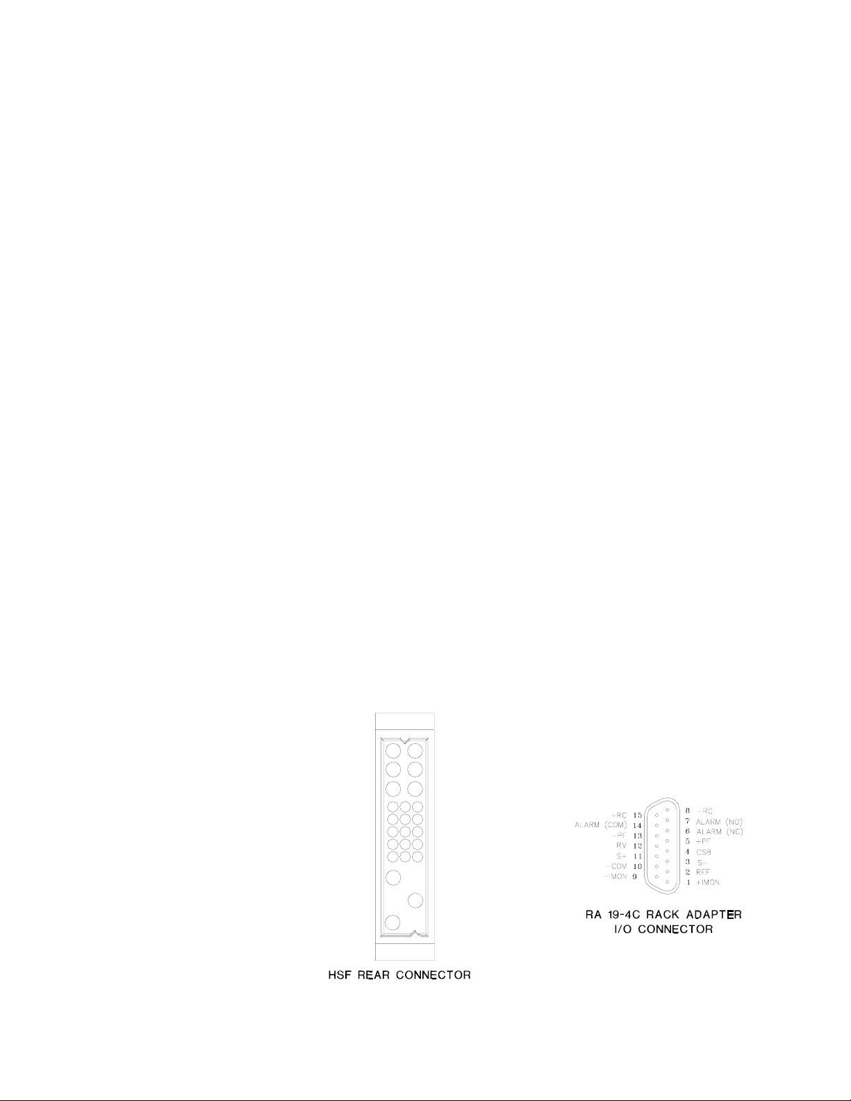
1 HSF Rear Panel Connector and RA 19-4C Rack Adapter I/O Connector .................................................. 1
2 Power Rating Vs. Temperature (Input: 95 to 264V a-c).............................................................................. 3
3 Mechanical Outline Drawing Of The HSF 600W Power Supply ................................................................. 6
4 DIP Switch Configuration............................................................................................................................ 7
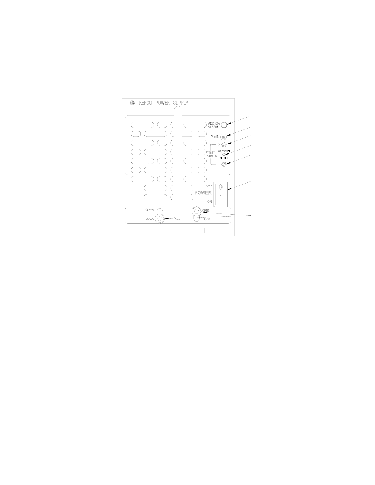
5 Front Panel Controls, Indicators and Test Points ....................................................................................... 8
6 DIP Switch Settings for Control of Output Voltage ..................................................................................... 9
7 Connections For Remote Voltage Control ................................................................................................ 10
8 DIP switch settings for VDC ON/ALARM Power Options ......................................................................... 10
9 DIP Switch Settings for Using RESET button or Remote ON-OFF .......................................................... 11
10 DIP switch settings for Optically Coupled Logical Alarm .......................................................................... 13
11 Output Alarm Circuit Optically Isolated..................................................................................................... 13
12 ±PF Power Failure Optocoupler Timing Diagram..................................................................................... 14
1 HSF Rear Connector Pin Assignments ......................................................................................................2
2 Output Ratings and Specifications ..............................................................................................................3
3 Power Supply Ratings and Specifications ..................................................................................................4
4 Minimum Conditions for Relay and LED Operation ....................................................................................9
5 W Models: Conditions for VDC ON/ALARM LED Operation Powered by Output .....................................10