Kessler CINESHOOTER User manual

http://kesslercrane.com/support
support@kesslercrane.com
574-400-2251
COMPLETE USER MANUAL

TABLE OF CONTENTS
CINESHOOTER SYSTEM
TABLE OF CONTENTS
ITEMS INCLUDED
Features and Functions ............................................................................................................2-3
• Main Components ................................................................................................................2
• Additional Features ...............................................................................................................2
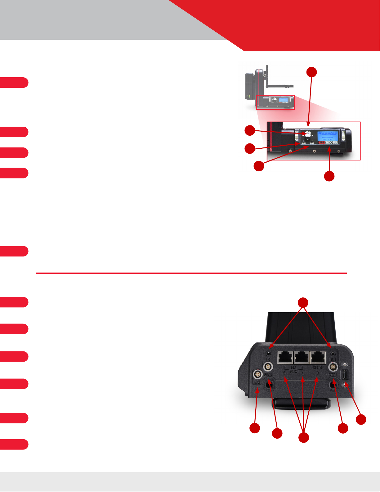
• On-Board Controls ................................................................................................................3
• Ports & Power ....................................................................................................................3
Hardware Setup ....................................................................................................................4-9
• Before You Begin .................................................................................................................4
• Mounting your CineShooter Pan & Tilt Head .......................................................................................4
• Powering your CineShooter Pan & Tilt Head.......................................................................................4
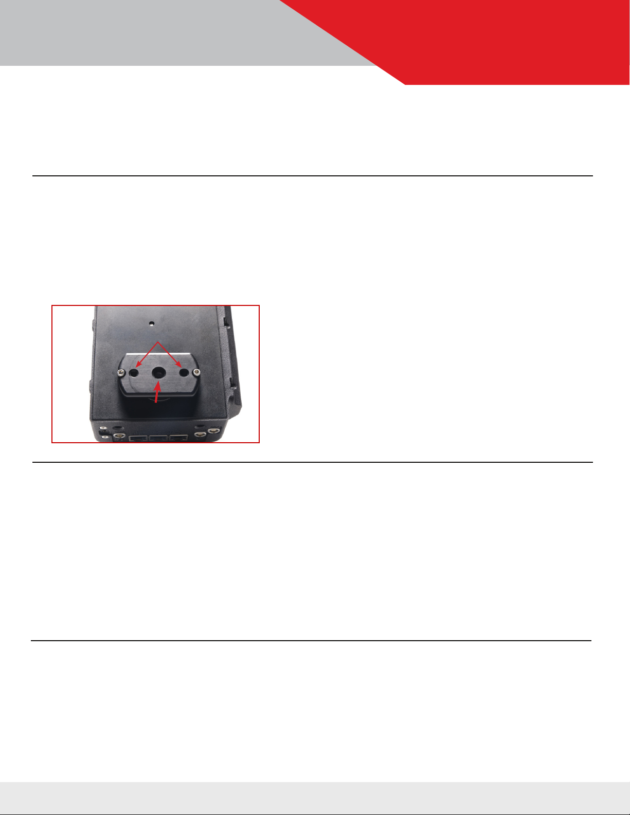
• Mounting your Camera ............................................................................................................4
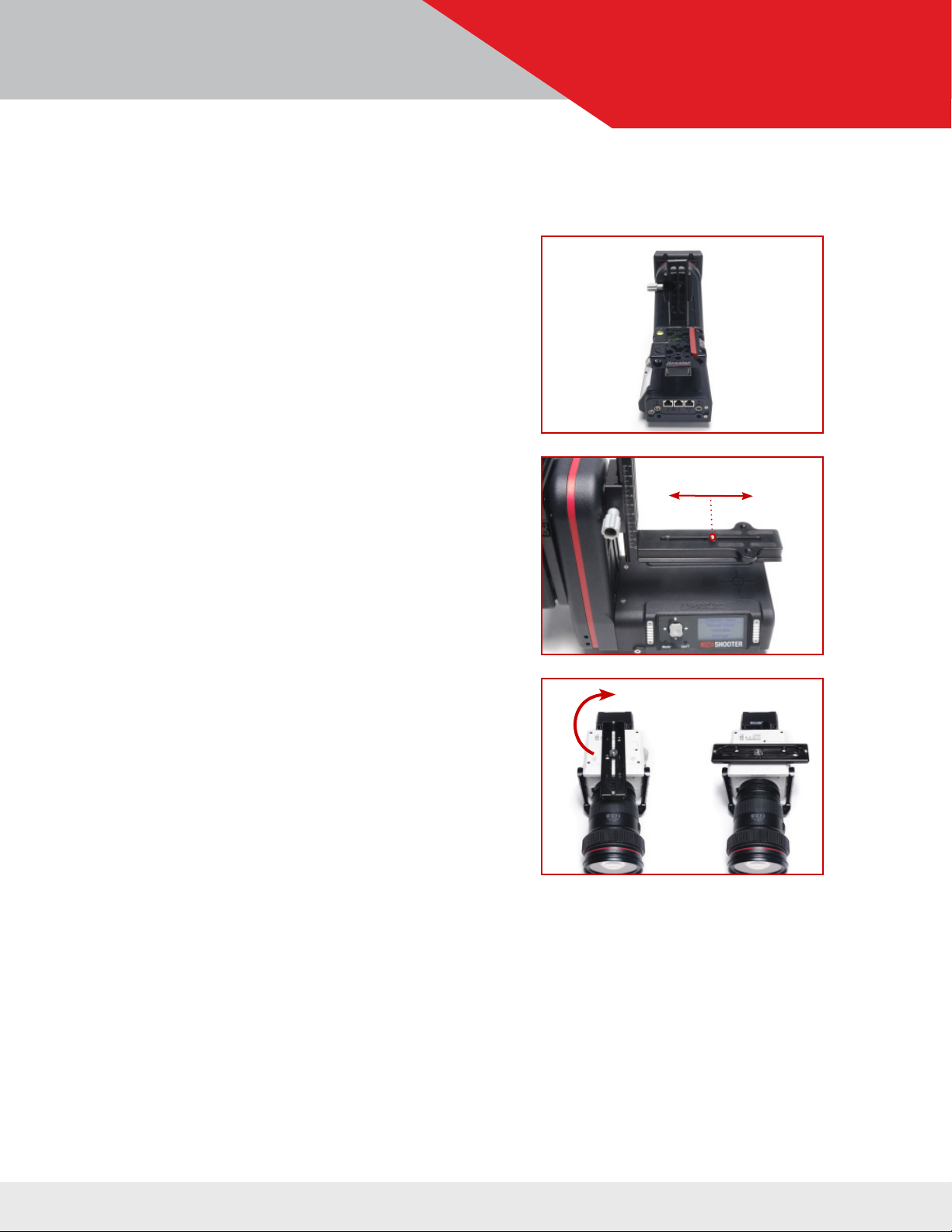
• Balancing your Camera ............................................................................................................5
• Tips on Balancing ...............................................................................................................5-6
• Finding Nodal Center ..............................................................................................................7
• Mounting to the L-Bracket or H-Frame ............................................................................................ 8
• Mounting in Roll Mode ............................................................................................................9
Accessory Installation ............................................................................................................10-15
• Heavy Duty Support Module ......................................................................................................10
• Smart Handle Module ..........................................................................................................11
• Adding an Additional Motor Axis ...............................................................................................12-15
Slide Motor Axis........................................................................................................12-13
PulleyConguration.............................................................................................12
Pulley Installation ............................................................................................13-15
Pan/Tilt Motor Axes.......................................................................................................16
FIZ Motor Axis ...........................................................................................................17
• Connectingan Intervalometer .....................................................................................................17
Using kOS ..........................................................................................................................18
• Connecting to kOS via USB ......................................................................................................18
• Connecting to kOS via WIFI ......................................................................................................18
CineShooter Remote App ...........................................................................................................19
• Pairing Phone to CineShooter Remote ...........................................................................................19
• Pairing PS4/XBOX Controller to CineShooter Remote .............................................................................19
Bridge Mode ........................................................................................................................20
• Using Bridge Mode ..............................................................................................................20
• Setting Up Bridge Mode ..........................................................................................................20
Shooting Modes .................................................................................................................21-22
• Program Move ..................................................................................................................21
• Manual Move .................................................................. ................................................21
• Turntable .......................................................................................................................22
• Settings ........................................................................................................................22
Setting Up a Move ................................................................................................................23-25
• Loop/Scrub .....................................................................................................................23
• Time Lapse .....................................................................................................................24
• Stop Motion ....................................................................................................................25
Updating Firmware ..............................................................................................................26-27
• Wireless Update via CineShooter Remote App ....................................................................................26
• Manual Update via Kessler Support Page ........................................................................................27
Getting Creative .................................................................................................................28-29
• Standard Mode .................................................................................................................28
• Roll Mode ......................................................................................................................28
• Arc Mode ......................................................................................................................29
• Rolling Arc Mode ...............................................................................................................29
Troubleshooting...................................................................................................................30-31
Term Reference Guide ...............................................................................................................32
Contact & Support ...................................................................................................................33
• Questions? .....................................................................................................................33
• Idea? ..........................................................................................................................33
• Share Your Work ...............................................................................................................33
USER GUIDE
• Heavy Duty Support Module
• Smart Handle Module
• Any Compatible Kessler Slider
• Slide Motor
• Pan/Turntable Motor
• FIZ Motor
• Camera Control Cable
• Bridge Cable
• Second Shooter Pro/Plus Controller
(for bridging)
• External intervalometer
• CineShooter Remote App
• kOS Software
• Digital Control Center (Coming Soon)
• 1x CineShooter Pan & Tilt Head
• 1x Adjustable Arca-Swiss Mounting L-Bracket
• 1x Power Port Cover (Installed)
• 1x 12V 5A Power Supply with 5.5x2.1mm Barrel
(Center Positive)
• 1x 3 ft. USB-C Cable
• 1x 1/4”-20 and 3/8”-16 Camera Screws
• 1x Allen Key
• 1x QuickStart Guide
NOTE: Notallfeatureshavebeenenabledinthermware.Themanualwillnotprovide
awalkthroughorsetupofthatparticularfeatureuntilitisactivatedinthermware.
OPTIONAL ACCESSORIES

support.kesslercrane.com Page 2 of 33
USER GUIDE FEATURES & FUNCTIONS
CINESHOOTER SYSTEM
ON-BOARD
CONTROL PANEL
ARCA-SWISS PAN MOUNTING
FOOT (ALSO WITH 3/8”-16, AND 2X
1/4”-20 MOUNTING ON BOTTOM)
MAIN COMPONENTS (IN 3-AXIS SETUP)
*System shown with optional slider, slide axis motor, and Kwik Release Receiver.
For additional Axis setup information, see Table of Contents, or visit support.kesslercrane.com
CINESHOOTER PAN &
TILT HEAD
ADJUSTABLE
ARCA-SWISS CAMERA L-MOUNT
POWER & CONTROL
PORTS
NOTE: Thissystemisregularlymaintainedwithrmwareupdates.Itisrecommendedthatusersverifytheyarerunningthe
mostcurrentversionofrmwarebeforeoperatingtheCineShootersystemforthersttime.
Firmware can be downloaded and installed wirelessly via the CineShooter Remote mobile companion app, or it can be
downloaded manually at kesslercrane.com/support and installed via the USB-C port located on the end of the Pan & Tilt
Head.
POWER PANEL
JOYSTICK
(UP, DOWN, LEFT, RIGHT, & ENTER CLICK)
PAN AXIS NODAL CENTER
REFERENCE POINT
ARCA TIGHTENING KNOB/TILT AXIS
NODAL CENTER REFERENCE POINT
MENU BUTTON/ PAUSE/
BACK
SHIFT BUTTON/
AXIS SELECTION (DOUBLE CLICK)
NODAL HEIGHT MARKINGS
(IN CENTIMETERS)
ADDITIONAL FEATURES
MAGNETS FOR MAGPAK / OPTIONAL
V-MOUNT / GOLD MOUNT BATTERY PLATE
MOUNT
BARREL CONNECTOR
FOR AC POWER

support.kesslercrane.com Page 3 of 33
USER GUIDE FEATURES & FUNCTIONS
CINESHOOTER SYSTEM
Directional Joystick
For on-board programming and control, the directional joystick canbe used to navigate through
the menu system, and alsocontrol the Left/Right movement of the Slider motor, Left/Right
movement ofthe pan motor, the Up/Down movement of the tilt motor, spin Left/Right if using a
turntable, or rotate Left/Right if using a FIZ motor.
Enter/Select Button
Click the joystick to hit“enter” and make selections within the menu.
Menu Button
Navigate backwards to the previous menu page, or to return to the main menu
Shift Button
When used in conjunction with other buttons, this button allows for secondary controls, and secondaryaxes
when utilizing motors driven through a bridged Second Shooter/Plus/Pro controller or wireless 2-axis
expansion module.
Shift+ Directional arrows increases speed during set to allow moves to be programed faster. (NOTE: The head
defaults to Quiet Mode. This option is only available when Quiet Mode is disabled.)
Double click Shift to cycle through axes.
Shift toggles backlight on/off during time lapse move.
Backlit Display Screen
Easy-to-navigate display screen that permits onboard programming and operaiton
EXT Port
This is theCANbus port, and is for wired bridging with accessories such as a Second Shooter Pro/Plus
controller, and other control devices.
PWR Port
This is an industry-standard 2-pin Lemo power port, and is compatible with AC wall power, as well as a wide
variety of third-party power solutions that use Pin-1 GND.
I/O Ports
Used to support our Smart Handle and FreeMotion feature, or for triggering cameras (with corresponding
trigger cable), and connecting external intervalometers and bulb-ramping devices, such as Ramper Pro.
CAT5 Axis Ports
Allows for the CineShooterheadto control up to 3 additional external motor axes (typically Slide, FIZ, or
Turntable), or any other combination of motors available. Each axis connects to corresponding port via
provided CAT5 cable.
CTRL Port
This is forI2C and UART support, and allows CineShooter to communicate with Dragonframe software, as well
as hardwired ethernet for remote control via our dedicated web server.
USB-C Port
The USB-C Port is for hardwiring the system for use through Kessler kOS software, as well as hardwire option
for rmware updates (rmware can also be wirelessly updated via the mobile app as well).
A
B
C
D
E
F
G
H
I
J
K
B
A
C
D
E
FG
K
ON-BOARD CONTROLS
PORTS & POWER
H
J
I

support.kesslercrane.com Page 4 of 33
USER GUIDE HARDWARE SETUP
CINESHOOTER SYSTEM
MOUNTING YOUR CINESHOOTER PAN & TILT HEAD
TosetupyourCineShooterPan&TiltHead,werecommendrstmountingyourCineShooterto
a secure platform (A slider, a tripod, or some other camera mounting base).
The mounting foot of the CineShooter is an Arca-Swiss base that works with our Kwik Release
Receiver, as well as a variety of other third party Arca-based mounts.
For those not using an Arca plate— on the bottom of the Arca foot
is one on-center 3/8”-16 threaded hole, and two ¼”-20 threaded holes
on either side to provide alternative ways to mount your equipment to
non-Arca bases.
POWERING YOUR CINESHOOTER PAN & TILT HEAD
There are many ways to power your CineShooter. Depending on what options and accessories
you’re using, you have the option of powering your system via:
• The provided 12v barrel connector AC power supply
• Kessler MagPak battery (w/ 12v barrel connector cable)
• V-Mount Battery (requires add-on Battery Plate option)
• Gold Mount/AB Mount Battery (requires add-on Battery Plate option)
• Batteries and power devices with Lemo 2-pin power cable (Pin-1 GND)
MOUNTING A CAMERA TO YOUR CINESHOOTER PAN & TILT HEAD
There are two main things to keep in mind when mounting your camera to the CineShooter:
• The balance/weight distribution of your camera
• The placement of your sensor on Nodal Center
1/4”-201/4”-20
3/8”-163/8”-16
BEFORE YOU BEGIN
CineShooters ship with a protective screen covering on the LED screen. We suggest removing
thisprotectivelmbeforeusingyourCineShooter.

support.kesslercrane.com Page 5 of 33
USER GUIDE HARDWARE SETUP
CINESHOOTER SYSTEM
BALANCING YOUR CAMERA
Before mounting your camera to the CineShooter, we strongly recommend balancing your
camera. This ensures optimal performance of your system and avoids potential issues.
Balance becomes more crucial with higher weight payloads. Achieving perfect balance is
ideal, however approximate balance will also help avoid issues on a higher weight payload.
For Standard Mode Shooting:
It is particularly important to achieve balance from
front to back, as well as being mindful of the vertical
center of gravity on your camera to avoid potential
jitters, camera shake, axis “fault errors”, or odd be-
havior in motion.
TIPS ON BALANCING
There are several ways to balance your camera, here are three methods.
ON-BOARD TEST
For Roll Mode Shooting:
It is suggested to be mindful of the left to right
balance on your camera while making sure your lens
and sensor align directly on the “tilt” nodal plane.
Also note the height and width of your camera build
to ensure clearance when completing a full roll
rotation.
Using an unpowered CineShooter Pan & Tilt Head,
mount your camera to the L-Bracket or H-Frame and
observe any movement along the tilt axis. When
unpowered, the tilt motor has very little resistance and
will help indicate whether your camera build is balanced
enough. A balanced camera won’t move the tilt axis. An
unbalanced camera will tilt forward or backward.
If the camera tilts down, it is front heavy.
If the camera tilts up, it is back heavy.
Note: If your full camera build does not move the tilt axis upon mounting, you are likely within a safe balance and
additional adjustment isn’t necessary.
ItisrecommendedtouseanArca-SwissplatecoupledwithourKwikReleaseReceiver.This
allows for an additional range of adjustment, sliding forward or backward to help counter the
balance of your camera. Otherwise, adjust your build by shifting accessories and adding counter
weight to help offset the weight. Repeat the test on the CineShooter until the camera feels
relatively balanced.

support.kesslercrane.com Page 6 of 33
USER GUIDE HARDWARE SETUP
CINESHOOTER SYSTEM
TIPS ON BALANCING (CONT’D)
SIMPLE FULCRUM TEST
A more rudimentary method is the use of
asimplefulcrumonaat,levelsurface
(a pen, dowel rod, or spare 15mm camera
rodwillallwork.)Witharmhandonyour
camera, align the ¼”-20 or 3/8”-16 mounting
hole on the bottom of your camera to your
fulcrum point.
Hold the camera level on the fulcrum and carefully loosen your grip. If the camera falls
forward, you are front heavy. If it falls backward, you are back heavy.
Adjust your build by shifting accessories, adding counter weight, or simply shifting your
mounting plate forward or back on your camera to help offset the weight. Repeat the test on
the fulcrum until the camera feels relatively balanced.
Note the new measured balance point. Using that reference point, center your camera on the
L-Bracket or H-Frame of the CineShooter.
NOTE: Balancing the camera by shifting your mounting plate may cause you to move the camera off the nodal
center point. For most shooting circumstances, it is better to have a balanced camera than a perfect nodal
center.
TRIPOD TEST
Usingauidheadtripod,mountyourbuilt-up
camera to the tripod head and loosen the tilt drag
until you start to feel the head moving without
resistance. Leveling the camera out, loosen your
grip of the camera and see which direction the
camera tilts.
If the camera tilts down, it is front heavy.
If the camera tilts up, it is back heavy.
Adjust your build by shifting accessories, adding counter weight, or simply shifting your
mounting plate forward or back on your camera to help offset the weight. Repeat the test on
the tripod until the camera feels relatively balanced.
Note the new measured balance point. Using that reference point, center your camera on the
L-Bracket or H-Frame of the CineShooter.
X✓

support.kesslercrane.com Page 7 of 33
USER GUIDE HARDWARE SETUP
CINESHOOTER SYSTEM
FINDING NODAL CENTER
Nodal Center is achieved when the sensor is perfecty aligned with both the pan and tilt axes on
your system (indicated with the cross marker on the top of the base of the CineShooter Head,
and on the Tilt Axis knob.
Nodal Center is ideal for VFX shots, shots that required 3D Tracking, virtual production, and
when doing more precise and measured camera movement, but is NOT necessary for regular
operation. Having a balanced rig is more important than placing your sensor directly on the
nodal point.
If achieving nodal center is crucial to your production, we recommend doing the fulcrum test
from the point where your sensor plane is, as opposed to the mounting holes on the base of your
camera. This well help you dial in the balance while still maintaining a nodal center point.
To achieve nodal center, there are 3 directions of adjustment to be mindful of:
• The vertical alignment (which is located by a notch marking on the L-Bracket Arca Mount)
• The horizontal alignment (Which is located by the perpendicular line in the crosshair
marking on the top of the CineShooter Base as seen in the photo.) Note: This alignment can
be automatically achieved when mounting a Kessler Kwik Release Receiver using the two
1/4”-20 tapped holes on the L-Bracket or H-Frame.
• The forward/back alignment. (Which is located by the horizontal line in the crosshair
marking on the top of the CineShooter Base as seen in the photo.) Note: This alignment
requires a Kessler Kwik Release plate, or some other Quick Release plate that allows for
slide adjustment of your camera build.
Make sure your camera sensor is centered with all 3 marking points located on the CineShooter
head. Depending on how you mount your camera, you may already be centered from left to
right, but have adjustments from front and back or up and down.
NOTE: As an added reference point, an additional notch marking is engraved on the underside of the L-Bracket and
H-Frame to better help align 1/4”-20 and 3/8”-16 mounting screws at the nodal center.
Vertical Alignment Notch Horizontal
Alignment Notch
Forward/Backward
Alignment Notch

support.kesslercrane.com Page 8 of 33
USER GUIDE HARDWARE SETUP
CINESHOOTER SYSTEM
MOUNTING TO THE L-BRACKET OR H-FRAME
There are several ways to mount your camera to the CineShooter Pan & Tilt Head. We suggest
rstremovingtheL-BracketorH-Frameandmountingyourcameratothebracketrstbefore
installing onto the head.
We also recommend powering your CineShooter Head before mounting your camera and
L-Bracket or H-Frame into the Arca-Swiss receiver plate(s) built into the CineShooter. This will
providealevelofresistancetothemotorsasyoumountyourcameratoavoidanydiculties
such as camera “crashing” on the tilt axis if the camera payload is too high or unbalanced.
For standard operation, you may:
• Mount directly to the horizontal slide slot available
on both the standard L-Bracket bracket or H-Frame
supplied in the Heavy Duty Mounting Module using
the supplied ¼”-20 or 3/8”-16 camera screws.
• Mount a Kessler Kwik Release Receiver to the two
centered-on-nodal tapped holes
• Mount a third-party quick release system using any of
the available 3/8”-16 or ¼”-20 holes or slots located
on the L-Bracket or H-Frame.
• Remove the provided L-Bracket or H-Frame and
mount any third-party Arca-based L-Bracket such as
L-Brackets offered by 3 Legged Thing, Really Right
Stuff, or Kirk.
1/4”-201/4”-20
1/4”-20 or 3/8”-161/4”-20 or 3/8”-16

support.kesslercrane.com Page 9 of 33
USER GUIDE HARDWARE SETUP
CINESHOOTER SYSTEM
MOUNTING IN “ROLL MODE”
For Roll Mode operation, you may:
• Mount your camera using a Kwik Release Receiver
oriented 90 degrees from standard mode mounted
using the horizontal slide slot available on the
standard L-Bracket using the supplied ¼”-20 or
3/8”-16 camera screws.
• Mount your camera directly to the horizontal slide
slot available on the standard L-Bracket using
the supplied ¼”-20 or 3/8”-16 camera screws.
Just orient your camera 90 degrees so the lens is
pointing toward the ports side.
• Keep your Kwik Release Receiver oriented
normally, but instead orient your Arca-Swiss plate
that’s fastened to your camera 90 degrees so it’s
perpendicular to the direction of your lens.
NOTE: When shooting in Roll Mode, users are limited to using the standard L-Bracket and cannot have the Heavy
Duty Mounting Module installed.
Also, for a perfect roll, make sure your sensor and lens are aligned to the nodal center “Tilt Axis” marking point,
otherwise an undesirable wobble may occur.

support.kesslercrane.com Page 10 of 33
USER GUIDE ACCESSORY INSTALLATION
CINESHOOTER SYSTEM
Screw in threaded rods into port end of CineShooter.
Screw in end plate to the newly installed rods using
the provided screws and 5/32 allen wrench.
Remove the L-Bracket from the Mini Kwik Release
Receiver located on the CineShooter.
Loosen the Mini Kwik Release Receiver located on
both the CineShooter head, and the end plate.
Take the H-Frame and slide into both Mini Kwik Release
Receivers. Adjust the height and tighten down.
Mount camera.
Note: The center point for the H-Frame is slightly off-center to
allowforcameraswithawiderprole.Thesidewiththelarger
hole on the horizontal plate should face outward, closer to the
side of the heavy duty support end plate.
1.
HEAVY DUTY SUPPORT MODULE
The Heavy Duty Support Module is designed to increase the max weight capacity from 15 lbs.
to 25 lbs.
2.
3.
4.
5.

support.kesslercrane.com Page 11 of 33
USER GUIDE ACCESSORY INSTALLATION
CINESHOOTER SYSTEM
Using the provided screws and allen wrench, install
the Smart Handle Module to the battery plate end of
the CineShooter.
Run the coiled cable along the base of the
CineShooter and plug the jack into the “In” port on
the ports panel of the CineShooter Pan and Tilt Head
1.
SMART HANDLE MODULE
The Smart Handle Module is intended to function as both a grab point for carrying and
adjusting your CIneShooter Pan & Tilt Head, as well as an interface to enable and interract with
the FreeMotion feature.
2.
1.
2.
3.
INSTALLATION
OPERATION
NOTE: The Smart Button only activates FreeMotion when programming a move, otherwise the function is disengaged
and the Smart Button will not free up the motors.
To operate, begin by programming a new camera move.
Once SET 1ST KEY FRAME is displayed on screen, press and hold the FreeMotion button
on the Smart Handle with one hand, and position the camera mounted to the L-Bracket or
H-Frame to desired position with the other hand, sliding along the slider (if using one).
Once the camera is in the desired position, let go of the FreeMotion button on the Smart
Handle. Then hit Enteronthejoysticktosetyourrstposition.Repeatstep2untildesired
number of keyframes are set.

support.kesslercrane.com Page 12 of 33
USER GUIDE
SMALL PULLEY PULLEY STORAGE PIN
LARGE PULLEY
ACCESSORY INSTALLATION
CINESHOOTER SYSTEM
SLIDE MOTOR AXIS
The most common pairing with the CineShooter Pan & Tilt Head, the Slide Motor axis allows
for programmed slider motion that provides push-ins, pull-outs, pedastals up and down (when
slider is mounted vertically), angled moves, parallel slides, and parallax movements.
PULLEY CONFIGURATION
Depending on your desired shot type, there are two different diameter pulleys provided with the
slidemotorthatcanbearrangedindiferentcongurationstoprovidethreedifferentgearratios
allowing for the adjustment of overall motor speed, operating volume, and torque.
Note: The metal pin on the Slider Motor stores the extra pulley when not in uses.
ADDING AN ADDITIONAL AXIS
Currently, there are several motor axes available that can be installed in various combinations
with your CineShooter system:
• Slide Motor
• Pan/Turntable Motor
• Tilt Motor (for creative
shooting)
• FIZ Motor
POSSIBLE PULLEY CONFIGURATIONS
Slider
Motor
Standard Speed / Torque
Standardcongurationformost
shooting conditions.
High Speed / Low Torque*
Interviewconguration,
or when noise is a concern.
Slider
Motor
Slider
Motor
Low Speed / High Torque
Verticalconguration,orforheavy
camera loads.
*Highspeed/lowtorquecongisnotcompatiblewithPocketDolly,ShuttleDolly,ShuttlePodorShuttlePodMini

support.kesslercrane.com Page 13 of 33
USER GUIDE
PULLEY INSTALLATION
To adjust pulley ratios, begin by removing the pulley installed on the Slide motor and pull
outward away from the motor.
To install the pulley, simply push the pulley onto the motor shaft while aligning the holes. Be
sure to hold the belt in place while installing.
ACCESSORY INSTALLATION
CINESHOOTER SYSTEM
1.
2.
Install the Small Pulley onto the Slider Motor.
The pre-installed belt (labled 110XL) on the Slider Motor is to be used in most
applications. However, if using the Small Pulley in conjunction with the Shuttle Pod, Shuttle
Pod Mini, Shuttle Dolly or Pocket Dolly v2.0 follow steps 5-6.
Place the smaller belt (labled 100XL) around the Small Pulley.
3.
4.
Mount the Slider Motor onto the Motor Mount utilizing the threaded holes nearest to the
pulley on the back side of the motor.
5.

support.kesslercrane.com Page 14 of 33
USER GUIDE ACCESSORY INSTALLATION
CINESHOOTER SYSTEM
Choose between the following pulley combinations: Fast, Normal and Slow.
FAST (LOW TORQUE)
*This combination is only compatible with CineSlider and Stealth sliders.
6.
NORMAL
SLOW (HIGH TORQUE)
*This combination requires the pulley from the Motor Mount Kit to be used on the slider.

support.kesslercrane.com Page 15 of 33
USER GUIDE ACCESSORY INSTALLATION
CINESHOOTER SYSTEM
Place screw cap back on slider pulley point. Push down pulley if needed and tighten.
Avoid over-tightening.
Connect CAT5 cable from Slider motor to the SLIDE port on the CineShooter Pan & Tilt
Head.
7.
8.

support.kesslercrane.com Page 16 of 33
USER GUIDE ACCESSORY INSTALLATION
CINESHOOTER SYSTEM
PAN & TILT MOTOR AXES
Because the CineShooter has Pan and Tilt motion built into the head, adding an additional Pan
and/or Tilt Axis would most likely be used for some sort of special effect (i.e. using the pan
baseinaturntableconguration,usingbothpanandtiltaxestomoveanobjectbeingphoto-
graphed for a more abstract camera motion, employing lighting queues, or some other creative
application of these motors. )
2.
4. Supply power to your CineShooter (See the “Powering Your CineShooter Pan & Tilt
Head” section of this manual for more information.)
The Pan/Turntable motor axis has 3/8”-16 and ¼”–20 holes on the underside to provide various
mounting options.
The Tilt motor axis has 2 pass-through (non-threaded) 1/4” holes intended for mounting to the
Pan motor but can be used on any third party cheeseplate, or home made rigging with correct
spacing and accepts ¼”–20 threading.
To mount to a slider: We recommend using a Kessler Kwik Release Receiver mounted to your
slider carriage, and a 3/8”-16 Kwik Short Plate mounted to the underside of your motor.
You may alternatively use our 3/8-16” Flat Mount adapter in lieu of the Kwik Release Receiver.
To mount the Tilt motor axis to the Pan motor: Simply align the two 1/4” pass-through holes on
the Tilt motor to the correspnding threaded ¼”–20 holes on the pan motor (or third party mount-
ing solution) and fasten together with the two provided screws and a 5/32 allen wrench.
When mounting for other applications: Simply utilize the 3/8”-16 and ¼”–20 holes on the base
of the pan motor to attach to your desired setup.
Connect CAT5 cable to the Pan/Tilt Motor and to either of the AUX ports on the CineShooter.
Connect CAT5 cable from the Tilt axis to either of the AUX ports on the CineShooter.
1.
3.

support.kesslercrane.com Page 17 of 33
USER GUIDE
CONNECTING AN INTERVALOMETER
For time lapse or stop motion, connect a Camera Control Cable to the “Out” port on the
CineShooter Pan & Tilt Head to the proper port on your camera.
ACCESSORY INSTALLATION
CINESHOOTER SYSTEM
FIZ MOTOR AXIS
The Kesser FIZ Motor will allow you to program lens adjustments on either the Focus, Iris, or
Zoom rings on your cinema (or any lens with a standard .8 pitched gearing).
To mount a FIZ Motor, your camera must be built on 15mm rods for the motor to attach to. Slide
motor onto 15mm rod, orienting the motor so the gearing aligns with the desired gear ring (Fo-
cus, Iris, or Zoom) on your lens.
If the motor has trouble engaging with the gearing of your lens, you may either try mounting
yourmotorwiththesecond15mmrodholeonthemotor,oryoumayiptheFIZmotortothe
opposite side of the motor mount. Adjust articulation until the lens and motor engage without
obstruction.
1.
Tighten down the FIZ Motor with the tightening nob so it is securely fastened to the 15mm rod.
2.
Connect FIZ adapter cable to CAT-5 cable, and the other end of the CAT-5 cable to one of the FIZ
ports on the CineShooter
3.

support.kesslercrane.com Page 18 of 33
USER GUIDE
CONNECTING TO KOS VIA WIFI
On the CineShooter, press the Menu button until the main
version screen is displayed. Once the version is displayed,
the Operation Mode menu will display.
IftheWiFimenuoptionreads“WiFiEnabled”,theWi
access point is active. Proceed to #4.
If the WiFi menu option reads “WiFi Disabled”, select it
and press the Enter button, your CineShooter will reboot
and will now say “WiFi Enabled”.
2.
3.
4.
5.
1.
USING KOS
CINESHOOTER SYSTEM
USING KOS SOFTWARE
To use the CineShooter system with kOS software, you will need kOS for CineShooter
installed on your Mac, Windows PC or iPad.
CONNECTING TO KOS VIA USB
Connect USB-C cable to computer and the CineShooter
Pan & Tilt Head.
Open kOS and click connect. Your CineShooter will
automatically connect to kOS.
2.
1.
On your computer or tablet you will now see a WiFi network named “CineShooter”. Connect to
that wireless network.
Once connected to the “CineShooter” network, open kOS and it will automatically connect to
your CineShooter via WiFi.

support.kesslercrane.com Page 19 of 33
USER GUIDE CINESHOOTER REMOTE APP
CINESHOOTER SYSTEM
PAIRING PHONE TO CINESHOOTER REMOTE
Connecting on iPhone
OniPhone,gotoyoursettings>Wi>andselect“CineShooter”.ReturntotheCineShooter
Remote app and the connection should automatically be made. For further support and
troubleshooting, see CineShooter Remote manual.
Connecting on Android
On Android, open the Settings App>Network & internet> Select Hotspot & Tethering> Wi-
Fi hotspot> and select “CineShooter”. Return to the CineShooter Remote app and the
connection should automatically be made. For further support and troubleshooting, see
CineShooter Remote manual.
PAIRING PS4/XBOX CONTROLLER TO CINESHOOTER REMOTE
PS4 Controller
Hold down the PS button and the Share button simultaneously for 5 seconds, or until the
lightsash.
Open your phone settings, go to Bluetooth, and select “DUALSHOCK 4 Wireless Controller”
from the list of new devices. Once connected, open the CineShooter Remote app and
click the Controller icon to pair. For further instructions, support, and troubleshooting, see
CineShooter Remote manual.
XBOX Controller
Hold down the Xbox One logo, located on the top center of the controller, until its backlight
startsashing.
Open your phone settings, go to Bluetooth, and select “Xbox One Wireless Controller”
from the list of new devices. Once connected, open the CineShooter Remote app and
click the Controller icon to pair. For further instructions, support, and troubleshooting, see
CineShooter Remote manual.
Table of contents
Other Kessler Camera Accessories manuals