Leica NA720 User manual

User Manual
English
Version 1.0
LEICA NA720/NA724/NA728/NA730
#
"!

NA720/NA724/NA728/NA730-1.0.1en 2
This manual contains important safety directions
(refer to section
"Safety directions")
as well as instructions for setting up the
instrument and operating it.
Please read this User Manual carefully to achieve maximum
efficiency from your Instrument.
Congratulations on your purchase of a new Leica Geosystems
automatic level.
Auto atic level
Auto atic level

NA720/NA724/NA728/NA730-1.0.1en 3
The type and the serial number of your instrument are indicated on
the label on the bottom of the base plate.
Write the type and serial number of your instrument in the space
provided below, and always quote this information when you need
to contact your agency or service workshop.
Type: Serial no.:
Product identification

NA720/NA724/NA728/NA730-1.0.1en 4
The symbols used in this User Manual have the following
meanings:
DANGER:
Indicates an imminently hazardous situation which, if not
avoided, will result in death or serious injury.
WARNING:
Indicates a potentially hazardous situation or an
unintended use which, if not avoided, could result in death
or serious injury.
CAUTION:
Indicates a potentially hazardous situation or an
unintended use which, if not avoided, may result in minor or
moderate injury and / or appreciable material, financial and
environmental damage.
Important paragraphs which must be adhered to in practice
as they enable the product to be used in a technically
correct and efficient manner.
Sy bols used in this anual

NA720/NA724/NA728/NA730-1.0.1en 5
Introduction .........................................................................7
Measurement preparation ...............................................10
Measuring ..........................................................................15
Checking and adjusting ...................................................20
Care and Storage ..............................................................22
Safety Directions ..............................................................25
Accessories.......................................................................32
Technical Data ..................................................................33
Index...................................................................................34
View of chapters
View of chapters

NA720/NA724/NA728/NA730-1.0.1en 6
Contents
Introduction ................................................7
Special features .......................................... 7
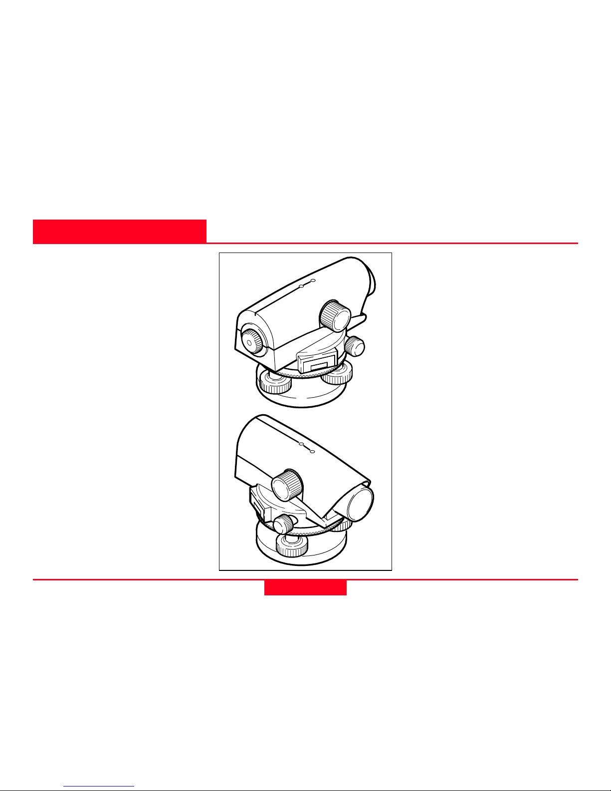
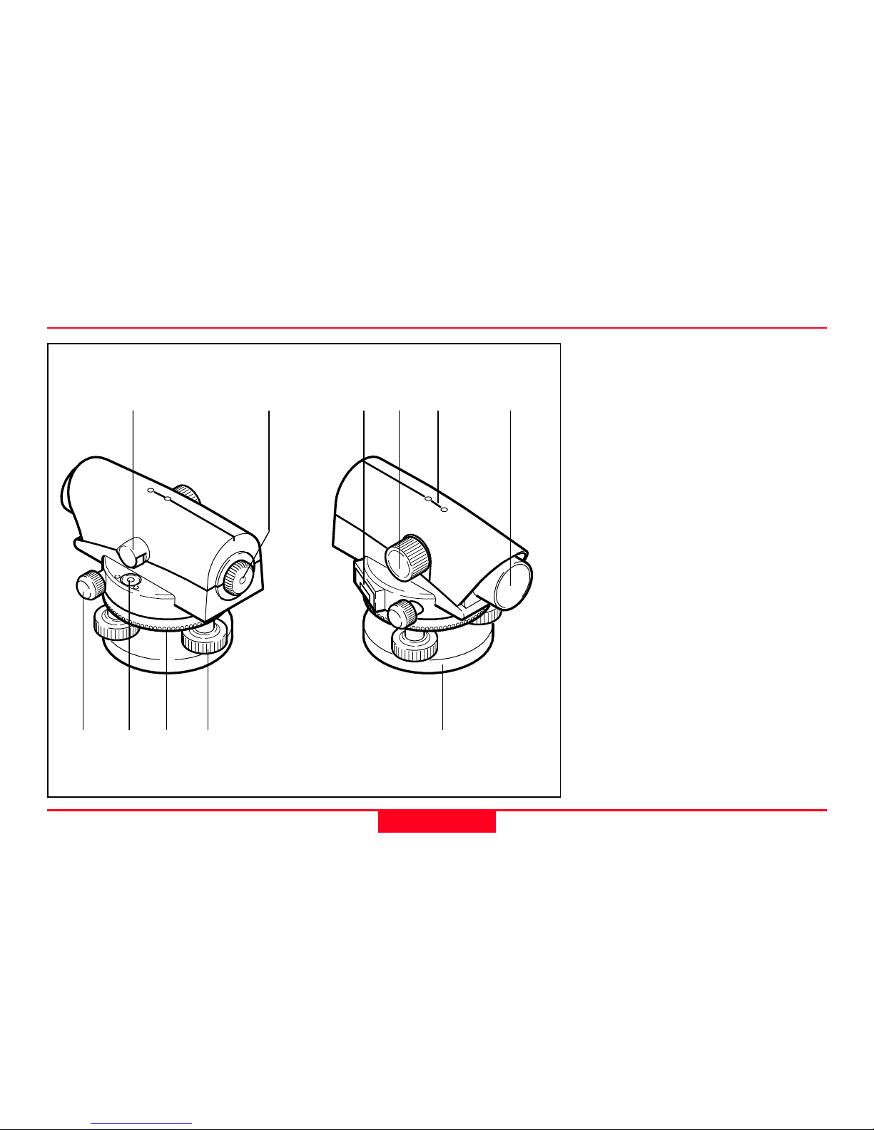
Important parts ........................................... 8
Technical terms and abbreviations ............ 9
Measurement preparation ......................10
Unpacking ................................................. 10
Setting up the tripod ..................................11
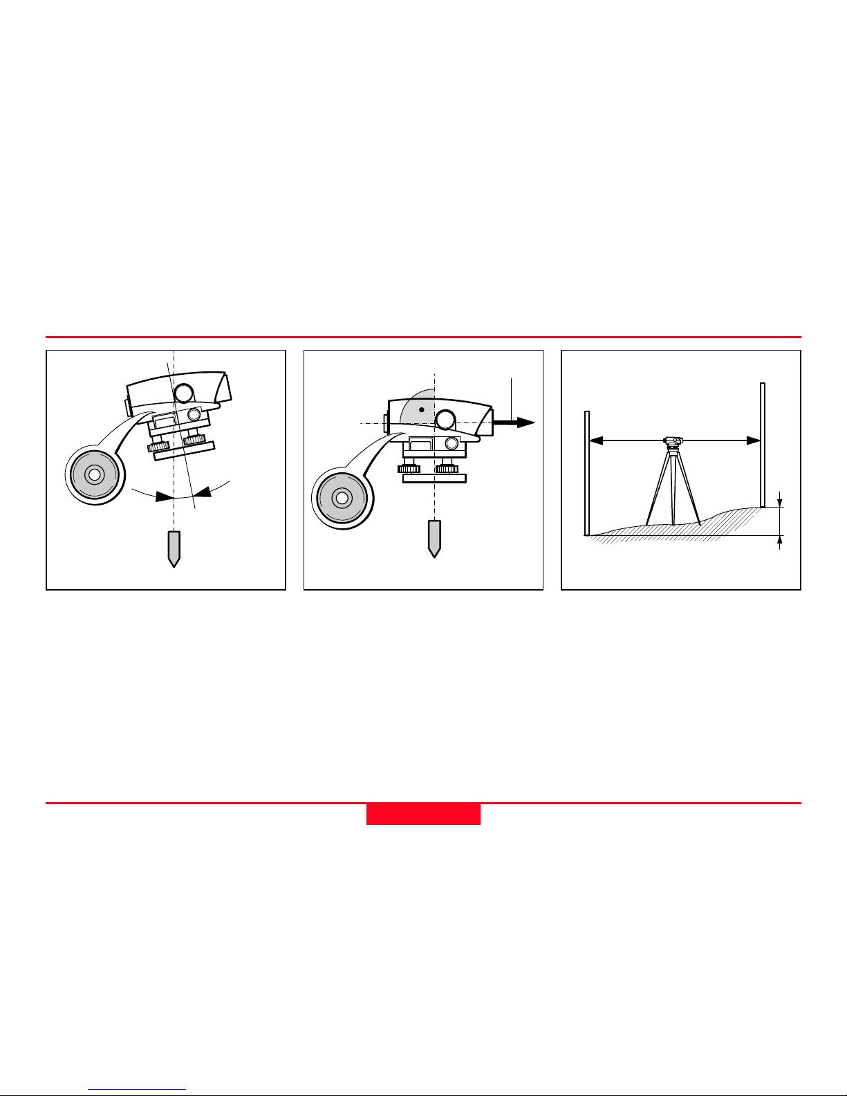
Levelling up............................................... 12
Focusing telescope .................................. 13
Centring .................................................... 13
Selection of angle reading........................ 14
Measuring .................................................15
Height reading .......................................... 15
Distance measuring .................................. 16
Angle measuring ....................................... 16
Line levelling ............................................. 17
Area levelling ............................................ 18
Levelling total station measuring ............. 19
Levelled stakeout ...................................... 19
Checking and adjusting ..........................20
Tripod ........................................................ 20
Circular level ............................................. 20
Checking and adjusting of the line-of-sight 21
Care and Storage .....................................22
Transport................................................... 22
In the field ................................................ 22
Inside vehicle ........................................... 23
Shipping ................................................... 23
Storage ..................................................... 23
Cleaning .................................................... 24
Safety Directions .....................................25
Intended use of instrument....................... 25
Permitted uses ......................................... 25
Adverse uses ........................................... 25
Limits of use ............................................. 26
Responsibilities......................................... 27
Hazards of use ......................................... 28
Accessories.............................................. 32
Technical Data .........................................33
Index..........................................................34
Contents

NA720/NA724/NA728/NA730-1.0.1en Introduction
7
Introduction Special features
NA-01
The NA720/NA724/NA728/
NA730 is a member of a new
generation of construction
levels.
Its innovative technology makes
the daily surveying jobs easier.
The instrument is ideally suited
for all applications of a reliable
and robust construction level.
The easy operation of the
instrument functions can be
quickly learned even by
inexperienced surveyors.
• Easy operation; quickly to
learn !
• Attractive design; low weight.
• Endless drive.
• Robust and reliable.
• Enables angle measurements
with horizontal circle
(choice of ° or gon).
• Resistant to water and dirt.
• Adaptable to all types of
tripods with 5/8" central fixing
screw.

NA720/NA724/NA728/NA730-1.0.1en Introduction
8
I portant parts
1 Endless drive (both sides)
2 Circular level
3 Knurled ring of adjustable
horizontal circle
4 Footscrew
5 Base plate
6 Objective
7 Coarse aiming device
(back/fore-sight for NA720/
NA724; optical sight with
point marking for NA728/
NA730)
8 Focusing knob
9 Cover glass for angle
reading ( ° or gon)
10 Eyepiece
11 Level mirror for NA720/
NA724; Level prism for
NA728/NA730
1
6
45
8 7
32
1011
NA-02
9

NA720/NA724/NA728/NA730-1.0.1en Introduction
9
Technical ter s and abbreviations
Backsight/Foresight/
Intermediate sight
For determining the height
difference (∆H) between the
ground points A and B the back
sight (R) is measured first
followed by the forward sight
(V). Additional points relating to
A are measured as intermediate
sight (S).
Plumb line
By centring the circular level the
instrument is nearly levelled up.
A small instrument tilt remains
(the vertical axis tilt).
Compensator
The compensator in the
instrument is responsible for
compensating the vertical axis
tilt enabling an exactly horizontal
aiming.
NA-05
NA--06
NA-04
A
B
RV/S
(∆H)
Plumb line
Vertical
axis tilt
Plumb line
Line-of-sight

NA720/NA724/NA728/NA730-1.0.1en Measure ent preparation
10
Gebrauchsanweisung
NA700kdkjodkolmdlkomömlkok
1 Level
2 User Manual
3 Allen key
4 Protective cover
Remove NA720/NA724/NA728/NA730 from the case and check for
completeness:
Unpacking
Measure ent preparation
NA-35
2
1
4
3

NA720/NA724/NA728/NA730-1.0.1en Measure ent preparation
11
NA-07
NA-08
When setting up the
tripod pay attention to a
horizontal position of the
tripod plate.
Heavy inclinations of the tripod
must be corrected with the
footscrews of the tribrach.
Setting up the tripod
1. Loosen screws of tripod legs,
pull out to required length and
tighten screws.
2. In order to guarantee a firm
foothold sufficiently press the
tripod legs into the ground.
When pressing the legs into
the ground note that the force
must be applied along the
legs.
Careful handling of tripod
•Check all screws and bolts
for correct fit.
•During transport always use
the cover supplied.
Scratches and other
damages can result in poor
fit and measuring
inaccuracies.
•Use the tripod only for
surveying jobs.
1. 1.
1.
2.
2.
2.
NA-09
NA-10
NA-11

NA720/NA724/NA728/NA730-1.0.1en Measure ent preparation
12
Levelling up
1. Place level onto tripod head.
Tighten central fixing screw of
tripod.
2. Turn footscrews of tribrach
into its centre position.
3. Centre circular level by
turning the foot screws.
Centring the circular level
1. Turn foot screws A and B
simultaneously in opposite
directions until bubble is in
the centre (on the imaginary
"T").
2. Turn foot screw C until bubble
is centred.
NA-12
NA-13
NA-14
B
A
C

NA720/NA724/NA728/NA730-1.0.1en Measure ent preparation
13
Focusing telescope
1. Aim telescope against a
bright background (e.g. white
paper).
2. Turn eyepiece until reticule is
sharp-focused and deep
black. Now the eyepiece is
adapted to your eye.
3. Aim telescope on staff using
the coarse aiming device.
4. Turn focusing knob until
image of staff is sharply
focused. If the eye is moved
up and down behind the
eyepiece the image of the
staff and the reticle may not
be displaced against each
other.
For possible centring over a
ground point:
1. Attach plumb bob.
2. Loosen central fixing screw
slightly and shift instrument
parallel on tripod until the
plummet is exactly over the
point.
3. Tighten central fixing screw.
Centring
NA-15
NA-16
NA-17
25
26
27

NA720/NA724/NA728/NA730-1.0.1en Measure ent preparation
14
0
Degree
35010
0
Gon
39010
Selection of angle reading
NA-42
Changing between °and gon:
1. Loosen screws with Allen key
and remove cover glass.
2. Turn cover glass.
3. Insert cover glass and tighten
screws again.
1.
2.
3.

NA720/NA724/NA728/NA730-1.0.1en Measuring
15
25
26
27
26
27
Measuring
Before starting field work
or after longer periods of
storage/transport of your
equipment check the field
adjustment parameters
specified in this User Manual.
Reduce possible
vibrations by holding the
tripod legs.
If the optical parts of
your instrument are dirty
of fogged, your measurements
can be affected. Keep clean all
optical parts of your instrument
and follow the cleaning
instructions specified in the
User Manual.
1. Setup instrument, level and
sharp-focus the reticule.
2. Setup level staff vertically
(refer also to Instruction
Manual of staff).
3. Roughly aim on staff using
the coarse aiming device.
4. Sharp-focus using the
focusing knob.
Height reading
5. Fine-aim on staff using the
endless drives.
6. Check if circular level is
centred (view level prism/
level mirror).
7. Read off height H at the
centre hair of the reticle.
Example above:
H = 2.585 m
d
NA-25
NA-18
H
H

NA720/NA724/NA728/NA730-1.0.1en Measuring
16
60
Degree
5070
0
Degree
35010
25
26
27
L
Result:
Distance d = 100 x L
Carry out steps 1 to 6 according
to height reading.
Reading:
Upper distance line: 2.670 m
Lower distance line: 2.502 m
Difference L: 0.168 m
Distance d: 16.8 m
Distance easuring
The NA720/NA724/NA728/
NA730 is equipped with a
horizontal circle. The graduation
is 1°or 1 gon.
Wanted:
Angle between point A and point
B.
Angle easuring
Carry out steps 1 to 6 according
to height measuring. By doing
so, align the vertical hair of the
reticle to the centre of the staff.
7. Turn Hz-circle to "0".
8. Align instrument to point B
and aim on the centre of the
staff.
9. Read off Hz-angle from Hz-
circle: Example above:
Hz = 60°.
NA-23
NA-26
NA-27
AB

NA720/NA724/NA728/NA730-1.0.1en Measuring
17
Wanted:
Height difference (∆H) between
point A and B.
Select instrument station
and staff location by
pacing off so, that approximately
the same target distances result
(d1 ≈d2; approx. 40 to 50m).
Procedure:
1. Setup instrument at I1.
Line levelling
2. Setup level staff vertically at
point A.
3. Aim on staff and read off and
take down height (backsight
R).
4. Setup level at the
changepoint 2, aim on staff
and read off and take down
height (foresight V).
5. Setup level at I2, aim on staff
at the changepoint 2 and
read backsight and take
down.
6. Carry out a foresight at
changepoint 3.
7. Continue in the same way
until height at point B is
measured.
Result:
∆∆
∆∆
∆H = sum backsight - sum
foresight
Point
No.
Back-
sight R
Fore-
sight V Height
A +2.502 650.100
2 +0.911 -1.803
3 +3.103 -1.930
B -0.981 651.902
Sum +6.516 -4.714 ∆H=
+1.802
Example of the booking:
NA-28
A
B
2
3
RV
RV
RV
I1I2I3
d1d2
∆H

NA720/NA724/NA728/NA730-1.0.1en Measuring
18
Wanted:
Height difference of several
reference points.
The required accuracy is
usually not very high
with such measurements.
Nevertheless, from time to time
read the staff on a stable
intermediate point (reading must
remain the same).
Area levelling
Procedure:
1. Set up instrument centrally
between the desired points.
The instrument telescope
may not be below the highest
measured intermediate point.
2. Set up staff vertically at
reference point A.
3. Aim on staff and read and
take down height (=backsight
to known point).
4. Set up staff vertically at
point 1.
5. Aim on staff and read and
take down height
(=measuring intermediate
point, intermediate sight)
6. Repeat steps 4 and 5 for
additional intermediate
points.
Height =
Height of station point
+ backsight (A)
- intermediate sight
Point
No.
Interm.
si
g
ht Hei
g
ht
A 592.00
R1 +2.20
⊗594.20
S1 -1.80 592.40
S2 -1.90 592.30
S3 -2.50 591.70
S4 -2.30 591.90
NA-29
RS1
A1
2
3
4
S2
S3
S4
7. The height of individual points
are:
Example of booking:
⊗ =Instrument horizon

NA720/NA724/NA728/NA730-1.0.1en Measuring
19
Wanted:
Position of several ground
points.
The levelling total station
measuring is normally
carried out during area levelling.
Levelling total station easuring
Procedure:
1. Sequence of measurements
is the same as with area
levelling. However, beside the
height read also the staff
section L (see chapter
"Distance measuring") and
the Hz-angle.
2. Transfer measured value into
the map - points are
determined by position and
height.
Levelled stakeout
The stakeout is the counterpart
to the levelling total station
measuring - map points are set
out in the field.
Procedure:
1. Set up instrument at a known
point, centre and level up.
2. Focus instrument and aim on
known orientation point.
3. Orient horizontal circle (Hz-
direction).
4. Move staff to stakeout point
on the basis of known values
(distance and Hz-angle,
height) and stakeout point
NA-36
NA-37
R
A1
2
Backsight to known point Measuring ground points
A

NA720/NA724/NA728/NA730-1.0.1en Checking and adjusting
20
12
Checking and adjusting
1. Level up instrument.
2. Turn instrument by 180°.
3. If bubble of level is outside
the circle then it should be
adjusted (see point 4).
NA-31
Circular level
Connection of individual
elements must always be tight.
1.Tighten the Allen screws (2)
moderately (if available).
2. Tighten the articulated joints
on the tripod head (1) just
enough to keep the tripod
legs open when you lift it off
the ground.
Tripod
NA-30
4. Correct the half error using
an Allen key and repeat steps
2 and 3 until the bubble of
level is in the centre in any
telescope direction.
NA-32
∆
∆/2
1. 2.
3.
Other manuals for NA720
1
This manual suits for next models
3
Table of contents
Other Leica Laser Level manuals

Leica
Leica Rugby 820 User manual

Leica
Leica Rugby 880 User manual

Leica
Leica LINO L6R User manual

Leica
Leica Lino L4P1 User manual

Leica
Leica TS12 Lite User manual

Leica
Leica Sprinter 150 User manual

Leica
Leica 3D Disto User manual

Leica
Leica NA720 User manual

Leica
Leica DISTODXT User manual

Leica
Leica Rugby 820 User manual

Leica
Leica DISTO D210 User manual

Leica
Leica Rugby 880 User manual

Leica
Leica Rugby 640G User manual

Leica
Leica Rugby 620 User manual

Leica
Leica N3-70 User manual

Leica
Leica Rugby 640 User manual

Leica
Leica DNA 10 User manual

Leica
Leica LS10 User manual

Leica
Leica Lino L4P1 User manual

Leica
Leica Rugby 670 User manual