manuals.online logo
Brands
  1. Home
  2. •
  3. Brands
  4. •
  5. KMC Controls
  6. •
  7. Control Unit
  8. •
  9. KMC Controls VEB-4303-SDL Series User manual

KMC Controls VEB-4303-SDL Series User manual

VEB-4303*SDL Series 2-Way, Steam-Rated, NPT Control Ball Valves 1 Installation Guide
Wiring
Installation Guide
2-Way, Steam-Rated, NPT, Control Ball Valves (3⁄4")
VEB-4303*SDL Series
Mounting
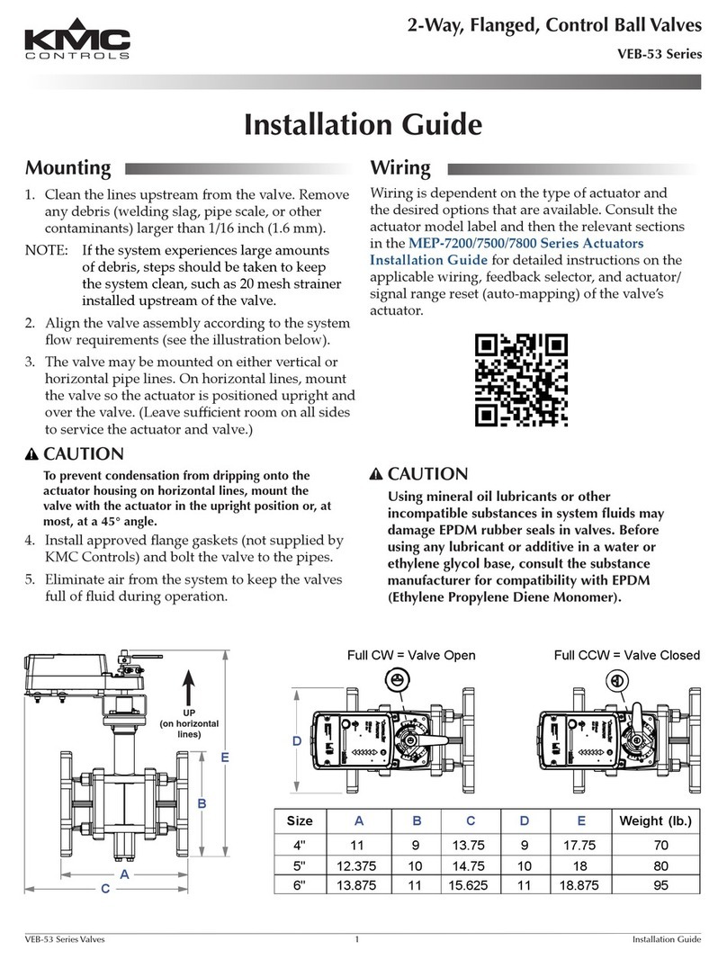
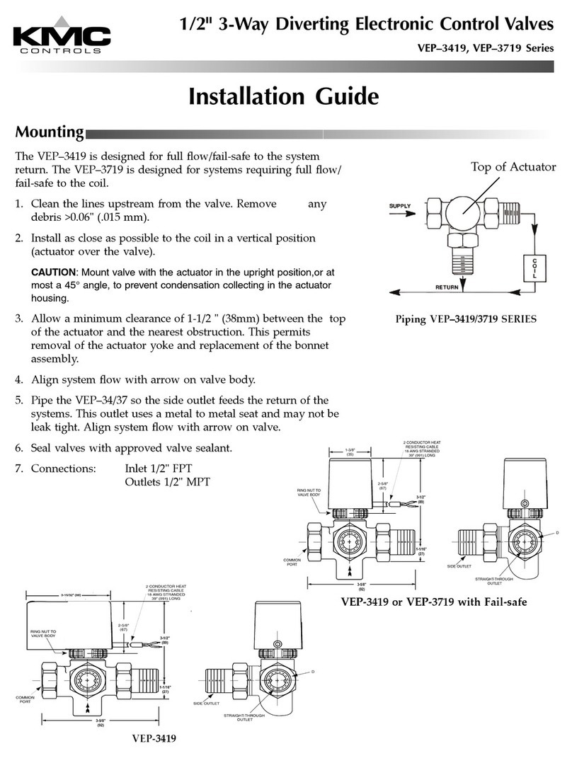
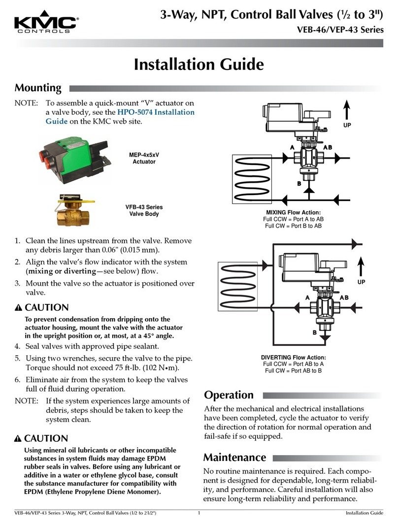
1. Clean the lines upstream from the valve. Remove
any debris larger than 0.06" (.015 mm).
2. Alignthevalve’sowindicatorwiththesystem
ow.
3. Mountthevalvesotheactuatorispositionedover
valve.
CAUTION
To prevent condensation from dripping onto the
actuator housing, mount the valve with the actuator
in the upright position or, at most, at a 45° angle. A
45° angle is recommended in steam applications.
4. Sealvalveswithapprovedpipesealant.
5. Usingtwowrenches,securethevalvetothepipe.
Torqueshouldnotexceed75-lbs.(102N•m).
6. Eliminate air from the system to keep the valves
fullofuidduringoperation.
NOTE: Ifthesystemexperienceslargeamountsof
debris,stepsshouldbetakentokeepthe
systemclean.
UP
Action:
Full CW = Valve Closed
Full CCW = Valve Open
CAUTION
Using mineral oil lubricants or other incompatible
substances in system fluids may damage EPDM
rubber seals in valves. Before using any lubricant or
additive in a water or ethylene glycol base, consult
the substance manufacturer for compatibility with
EPDM (Ethylene Propylene Diene Monomer).
Gear Disengagement
Button (see Caution
on the next page)
SYSTEM FLOW
Operate with Increasing Voltage
in Clockwise (CW) Direction
Operate with Increasing Voltage in
Counterclockwise (CCW) Direction
Connectwiringaccordingtothediagram.Seethe
Accessories/RepairPartssectionforconnection
accessories.
Theactuator’swiringcoverhastwo5/8"diameter
openingswithshuerbushingstoprovidesupport
for0.125"through0.4"diameterwire/cable.Usethe
HMO-4518for1/2"exibleconduit,theHMO-4520
compressionconnectorforplenumcable,orthe
HMO-4526femaleconnectorfor1/2"conduit.
CAUTION
To avoid overheating the valve’s actuator in steam
applications, be sure to use standard fiberglass
insulation to insulate the pipe near the valve. Also,
mounting the valve at a 45° angle is recommended
in steam applications.
VEB-4303*SDL Series 2-Way, Steam-Rated, NPT Control Ball Valves 2 Installation Guide© 2009 KMC Controls, Inc. 070-019-01A
KMC Controls, Inc.
19476IndustrialDrive
NewParis,IN46553
574.831.5250
www.kmccontrols.com;[email protected]
Operation
Aerthemechanicalandelectricalinstallations
havebeencompleted,cycletheactuatortoverifythe
directionofrotationfornormaloperationandfail-
safe if so equipped.
Accessories/Repair Parts
CME-1002 Singleauxiliaryswitch
CME-1004 Dualauxiliaryswitch
HMO-4518 Snap-inconnectorfor1/2"
exiblemetalconduit
HMO-4520 Compressionconnectorfor
plenumcable
HMO-4526 Femaleconnectorfor1/2"
conduit
HPO-5072 Ballvalvetoactuatorrepairkit
MEP-5372 Replacementproportional,fail-
safeactuator
VFB-4303*SX Replacementvalvebodywith
optionforusewithanMEP-4000
seriesactuator—seethedata
sheet for details
Specifications
SeetheVEB-4303*SDLseriesdatasheet(070-035-01).
Maintenance
Noroutinemaintenanceisrequired.Themotorsare
permanentlylubricatedandallinternalgear-train
componentsareoil-impregnated.Carefulinstallation
willalsoensurelongtermreliabilityandperformance.
Adjustments
Theactuatorisfactory-setwiththeOPERATE
selectorswitchintheclockwiseCWposition,and
theactuatorwillrotateclockwisewitha2–10VDC
increasingcontrolsignal.
For Clockwise Rotation
1. LeavetheOPERATEselectorswitchintheCW
position.
2. Depressthegeardisengagementbuonand
rotatethedrivehubfullycounterclockwisetothe
90 mark.
3. Determinewhatpositionthevalveshouldbeat2
VDCinput.
4. Ifneeded,positionthevalvelinkagetothefull
openorclosepositionasdeterminedinstep3.
Thisensuresthatasvoltageincreasesandthe
actuatorrotatesintheclockwisedirection,the
valverotatesintheproperdirection.
5. Securetheactuatorifneeded.
For Counterclockwise Rotation
1. Set the OPERATEselectorswitchintheCCW
position.
2. Depressthegeardisengagementbuonand
rotatethedrivehubfullyclockwisetothe0mark.
3. Determinewhatpositionthevalveshouldbeat2
VDCinput.
4. Ifneeded,positionthevalvelinkagetothefull
openorclosepositionasdeterminedinstep3.
Thisensuresthatasvoltageincreasesandthe
actuatorrotatesinthecounterclockwisedirection,
the damper or valve rotates in the proper
direction.
5. Securetheactuatorifneeded.
Fail-Safe Function
Thefail-safeswitchisfactory-setintheO position.
SelecteitherCW or CCWonthethree-positionswitch
tochoosethedirectiontheactuatorwillrotatewhen
powerislost.
Limit Min./Max. Travel with End Stop Screws
1. Ifdesired,loosentheminimumandmaximum
stopscrewsone-halfturn.
2. Slidethescrewstothedesiredpositions.
3. Tightenthestopscrews(9in-lbs.maximum).
CAUTION
Do not press the gear disengagement button when
the actuator is powered, under load, or driven
against the end stops. Balance the load and remove
power to the actuator BEFORE pressing the button.

Other KMC Controls Control Unit manuals

KMC Controls VEP–3420 Series User manual

KMC Controls

KMC Controls VEP–3420 Series User manual

KMC Controls HPO-9001 User manual

KMC Controls

KMC Controls HPO-9001 User manual

KMC Controls VEB-53 Series User manual

KMC Controls

KMC Controls VEB-53 Series User manual

KMC Controls VEP-43 Series User manual

KMC Controls

KMC Controls VEP-43 Series User manual

KMC Controls VEP-34190186 User manual

KMC Controls

KMC Controls VEP-34190186 User manual

KMC Controls KMD-5567 User manual

KMC Controls

KMC Controls KMD-5567 User manual

Popular Control Unit manuals by other brands

SPX Waukesha Cherry-Burrell W Series manual

SPX

SPX Waukesha Cherry-Burrell W Series manual

wtw IQ SENSOR NET MIQ/PS operating manual

wtw

wtw IQ SENSOR NET MIQ/PS operating manual

KERAFLO AYLESBURY KB installation guide

KERAFLO

KERAFLO AYLESBURY KB installation guide

Watts LFM114-8 Installation, operation and maintenance manual

Watts

Watts LFM114-8 Installation, operation and maintenance manual

AQUATROL POWERFLO AQT-315 Service manual

AQUATROL

AQUATROL POWERFLO AQT-315 Service manual

Sentiotec wave.com4 touch Instructions for installation and use

Sentiotec

Sentiotec wave.com4 touch Instructions for installation and use

ICC CAT 5e quick start guide

ICC

ICC CAT 5e quick start guide

Nice NDCC4001 Quick reference guide

Nice

Nice NDCC4001 Quick reference guide

Nordson EFD 750 Series installation guide

Nordson EFD

Nordson EFD 750 Series installation guide

SMART PCM11-i5 user guide

SMART

SMART PCM11-i5 user guide

Allen-Bradley DeviceNet 1203-GK5 user manual

Allen-Bradley

Allen-Bradley DeviceNet 1203-GK5 user manual

Hama 00176592 manual

Hama

Hama 00176592 manual

bolid S2000-AR8 Operation manual

bolid

bolid S2000-AR8 Operation manual

Becker HazzardControl HC520 Assembly and operating instructions

Becker

Becker HazzardControl HC520 Assembly and operating instructions

Ingersoll-Rand BAYLOAM335 installation instructions

Ingersoll-Rand

Ingersoll-Rand BAYLOAM335 installation instructions

HIMA DIO 24/16 01 manual

HIMA

HIMA DIO 24/16 01 manual

Kutai electronics EC-22 Operation manual

Kutai electronics

Kutai electronics EC-22 Operation manual

Hayward SelectaFlo SP0425 owner's manual

Hayward

Hayward SelectaFlo SP0425 owner's manual

manuals.online logo
manuals.online logoBrands
  • About & Mission
  • Contact us
  • Privacy Policy
  • Terms and Conditions

Copyright 2025 Manuals.Online. All Rights Reserved.