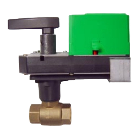
VEB-53 Series Valves 1 Installation Guide
B
E
A
C
Full CW =
Valve Open
Full CCW =
Valve Closed
Size
A B
C
D
E
Weight
(lb.)
4"
11 9 13.75 9 17.75 70
5"
12.375 10 14.75 10 18 80
6"
13.875 11 15.625 11 18.875 95
D
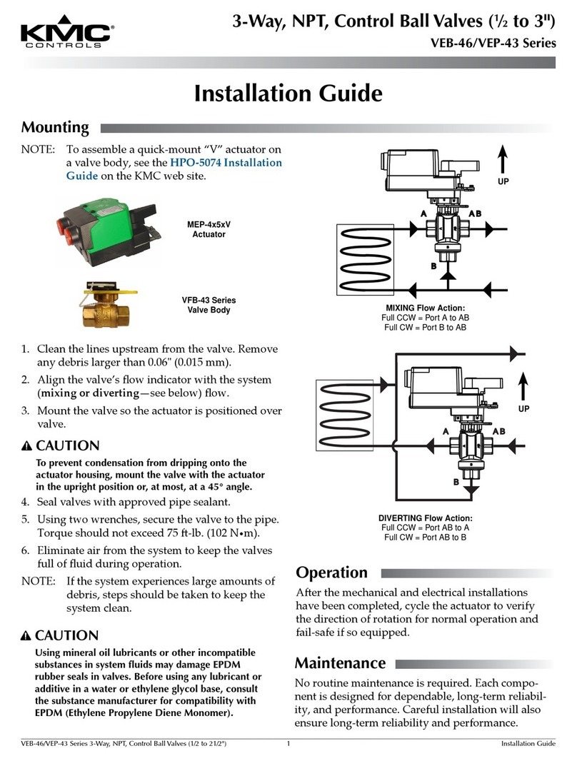
Installation Guide
2-Way, Flanged, Control Ball Valves
VEB-53 Series
Mounting 1
Wiring 1
Operation 2
Maintenance 2
Accessories/Repair Parts 2
Models and Specifications 2 Mounting
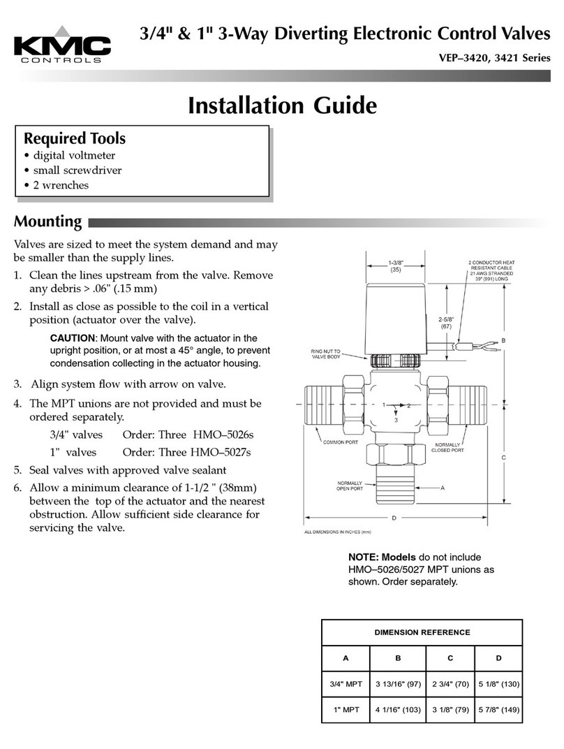
1. Cleanthelinesupstreamfromthevalve.Remove
anydebris(weldingslag,pipescale,orother
contaminants)largerthan1/16inch(1.6mm).
NOTE: Ifthesystemexperienceslargeamounts
ofdebris,stepsshouldbetakentokeep
thesystemclean,suchas20meshstrainer
installedupstreamofthevalve.
2. Alignthevalveassemblyaccordingtothesystem
owrequirements(seetheillustrationbelow).
3. Thevalvemaybemountedoneitherverticalor
horizontalpipelines.Onhorizontallines,mount
thevalvesotheactuatorispositioneduprightand
overthevalve.(Leavesucientroomonallsides
toservicetheactuatorandvalve.)
CAUTION
To prevent condensation from dripping onto the
actuator housing on horizontal lines, mount the
valve with the actuator in the upright position or, at
most, at a 45° angle.
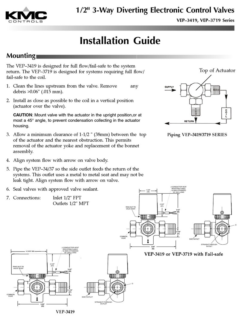
4. Installapprovedangegaskets(notsuppliedby
KMCControls)andboltthevalvetothepipes.
5. Eliminateairfromthesystemtokeepthevalves
fullofuidduringoperation.
UP
(on horizontal
lines)
CAUTION
Using mineral oil lubricants or other
incompatible substances in system fluids may
damage EPDM rubber seals in valves. Before
using any lubricant or additive in a water or
ethylene glycol base, consult the substance
manufacturer for compatibility with EPDM
(Ethylene Propylene Diene Monomer).
Wiring
Wiringisdependentonthetypeofactuatorand
thedesiredoptionsthatareavailable.Consultthe
actuatormodellabelandthentherelevantsections
intheMEP-7200/7500/7800 Series Actuators
Installation Guidefordetailedinstructionsonthe
applicablewiring,feedbackselector,andactuator/
signalrangereset(auto-mapping)ofthevalve’s
actuator.


