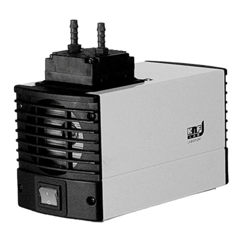
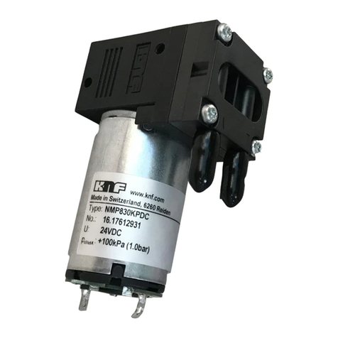
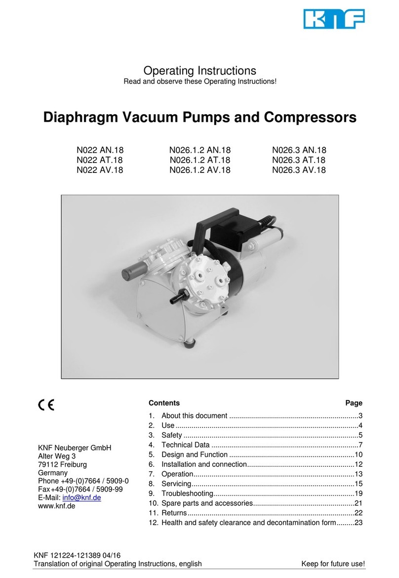
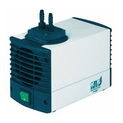
KNF N026 EX User manual

N026 EX
TRANSLATION OF ORIGINAL OPERATION AND
INSTALLATION INSTRUCTION
ENGLISH
KNF 059217 11/19 EN-US
ATEX
Notice!
Before operating the pump and the accessories, read the operating and installation instructions and observe
the safety notices!
DIAPHRAGM PUMP

Index
1 About this document ......................................................... 3
2 Use ................................................................................... 5
3 Safety.............................................................................. 11
4 Technical data ................................................................ 13
5 Design and function ........................................................ 15
6 Transport ........................................................................ 17
7 Installation and connection ............................................. 18
8 Operation ........................................................................ 23
9 Servicing ......................................................................... 26
10 Troubleshooting .............................................................. 38
11 Spare parts and accessories .......................................... 41
12 Returns ........................................................................... 42
13 Appendix......................................................................... 43
KNF Neuberger GmbH
Alter Weg 3
79112 Freiburg
Germany
Tel. +49 (0)7664/5909-0
Fax. +49 (0)7664/5909-99
www.knf.com

Diaphragm pump N026 EX About this document
Translation of Original Operation and Installation Instruction, english, KNF 059217 11/19 3
1 About this document
1.1 Using the operating and installation instructions
The operating and installation instructions are part of the pump.
àIn the event of uncertainties with regard to the content of the operating
and installation instructions, please contact the manufacturer (contact
data: see www.knf.com). Please have the type designation and serial
number of the pump ready.
àRead the operating and installation instructions before you commission
the pump.
àGive the operating and installation instructions to the next owner.
àKeep the operating and installation instructions within reach at all
times.
Project pumps For customer-specific project pumps (pump models that begin with "PJ" or
"PM"), there may be deviations from the operating and installation instruc-
tions.
àFor project pumps, also observe the agreed specifications.
Motor The operating and installation instructions apply for pumps without motor.
àAlso observe the operating instructions for the motor in the appendix.
1.2 Symbols and markings
Warning notice
WARNING
A notice that warns you of danger is located here.
Possible consequences of a failure to observe the
warning notice are specified here. The signal
word, e.g., warning, indicates the danger level.
àMeasures for avoiding the danger and its
consequences are specified here.
Danger levels
Signal word Meaning Consequences if not
observed
DANGER warns of immediate
danger
Death or serious injury
or serious damage will
result.
WARNING warns of possible dan-
ger
Death or serious injury
or serious damage are
possible.
CAUTION warns of a possibly
dangerous situation
Minor injuries or dam-
age are possible.
Tab.1

About this document Diaphragm pump N026 EX
4 Translation of Original Operation and Installation Instruction, english, KNF 059217 11/19
Explanations of pictograms
Pictogram Meaning
Warning of hand injuries through crushing
Warning of hot surface
Warning of electrical voltage
Warning of explosive materials
Observe the operating instructions
Tab.3
Other notices and symbols
àAn activity to be carried out is specified here (a step).
1. The first step of an activity to be carried out is specified here.
Follow other sequentially numbered steps.
This symbol indicates important information.

Diaphragm pump N026 EX Use
Translation of Original Operation and Installation Instruction, english, KNF 059217 11/19 5
2 Use
2.1 Proper use
The pumps are intended exclusively for transferring gases and vapors.
Responsibility of the owner
Operating parameters and
conditions
Only install and operate the pumps in accordance with the operating pa-
rameters and conditions described in Chapter 4 Technical data and Chap-
ter 2.3 Use in potentially explosive areas.
Only pumps that are fully assembled and in the condition as delivered may
be operated.
Make sure that the installation location is dry and that the pump is pro-
tected against rain, splash, gushing and drip water as well as from other
contaminants.
The pump is suitable for transferring potentially explosive atmospheres
and for operation in potentially explosive atmospheres.
The tightness of the connections between the pipes of the application and
the pump (or the connection of the pump) is to be checked at regular inter-
vals. Leaky connections carry the risk of releasing dangerous gases and
vapors from the pump system.
Requirements for the transferred
medium
Before transferring a medium, check whether the medium can be trans-
ferred danger-free in the specific application.
Before using a medium, check the compatibility of the media-contacting
components (see 4 Technical data) with the medium.
Risk of dangerous gas mixtures during pump operation if diaphragm
breaks: Depending on the medium being transferred, breakage of the di-
aphragm can result in a dangerous mixture if the medium mixes with the
air in the compressor housing or the surroundings.
Make certain that no risk of explosion arises even in extreme operating sit-
uations (temperature, pressure) and in the event of system breakdowns.
Only transfer gases that remain stable under the pressures and tempera-
tures that arise in the pump.
2.2 Improper use
The pumps are not suitable for use below ground.
The pumps are not suitable for transferring:
§Dusts
§Liquids
§Aerosols
§Biological and microbiological substances
§Explosives
§Fibers
§Food
Pumps that can produce both vacuum as well as overpressure may not be
used to simultaneously produce vacuum and overpressure.
This function can be made possible on a project basis upon consultation
with KNF Customer Service.
No overpressure may be applied to the suction side of the pump.
This function can be made possible on a project basis upon consultation
with KNF Customer Service.

Use Diaphragm pump N026 EX
6 Translation of Original Operation and Installation Instruction, english, KNF 059217 11/19
2.3 Use in potentially explosive areas
In potentially explosive areas (zones), only operate pumps of the appropri-
ate device category and temperature class.
The pumps have the following explosion protection designation:
Designation Description
Symbol for explosion-proof pumps
II Device group (See Chapter 2.4.1 Device groups)
2/2G Device category (See Chapter 2.4.2 Device cate-
gories for gas)
Ex Symbol indicates that the device complies with
one or more ignition protection types
H Symbol for ignition protection type (See Chapter
2.4.5 Ignition protection type)
II B + H2 Explosion groups (see Chapter 2.4.3 Explosion
groups)
T4 Temperature class (see Chapter 2.4.4 Tempera-
ture classes)
Gb Equipment protection level (See Chapter 2.4.6
Equipment protection level for gas)
Special operating conditions (See Chapter 2.4.7
Special operating conditions)
Tab.5
An ignition hazard assessment in accordance with standards DIN EN ISO
80079-36 and DIN EN ISO 80079-37 was performed for the pumps. The
protective goals were reached by applying ignition protection type con-
structional safety "c".
The explosion protection designation can also be found at the following lo-
cation:
§Type plate of the pump
Motor The pump motor must have at least the same explosion protection as the
pump.

Diaphragm pump N026 EX Use
Translation of Original Operation and Installation Instruction, english, KNF 059217 11/19 7
2.4 Explanations of the explosion protection designation
2.4.1 Device groups
Device group I Device group I applies for devices that are used in underground plants of
mines as well as their underground systems that could be endangered by
methane and/or combustible dusts.
Device group II Device group II applies for devices that are used in other areas that could
be endangered by an explosive atmosphere.
2.4.2 Device categories for gas
The device category describes the frequency and the duration of the oc-
currence of explosive atmospheres during operation.
Device cat-
egory
Description
1G Devices of this category are designed for use in areas in
which an explosive atmosphere consisting of a mixture of air
and gases, vapors or mists is present constantly or for long
periods of time or often.
1D Devices of this category are designed for use in areas in
which an explosive atmosphere consisting of a dust/air mix-
ture is present constantly or for long periods of time or often.
2G Devices of this category are designed for use in areas in
which it is to be expected that an explosive atmosphere con-
sisting of gases, vapors or mists forms occasionally.
2/2G Devices that extract from zone 1 and are designed for use in
areas in which it is to be expected that an explosive atmos-
phere consisting of gases, vapors or mists forms occasion-
ally.
2/-G Devices that extract from zone 1 but are not designed for in-
stallation in a potentially explosive atmosphere (zone).
2D Devices of this category are designed for use in areas in
which it is to be expected that an explosive atmosphere con-
sisting of a dust/air mixture forms occasionally.
3G Devices of this category are designed for uses in areas in
which it is to be expected that an explosive atmosphere re-
sulting from gases, vapors or mists occurs, though in all like-
lihood occurs only seldom and for a very short length of time.
3D Devices of this category are designed for uses in areas in
which it is to be expected that an explosive atmosphere re-
sulting from stirred-up dust occurs, though in all likelihood
occurs only seldom and for a very short length of time.
Tab.7

Use Diaphragm pump N026 EX
8 Translation of Original Operation and Installation Instruction, english, KNF 059217 11/19
2.4.3 Explosion groups
Combustible gases and vapors are classified according to explosion
groups (I, IIA, IIB and IIC) and temperature classes. The following table
shows the classification of the most common combustible gases and va-
pors.
T1 T2 T3 T4 T5 T6
I Methane – – – – –
IIA Acetone
Ethane
Ethyl ac-
etate
Ammonia
Ethyl chlo-
ride
Benzene
Acetic acid
Carbon
monoxide
Methane
Methanol
Methyl chlo-
ride
Naphthalene
Phenol
Propane
Toluene
i-amyl ac-
etate
n-butane
n-butyl alco-
hol
Cyclohex-
anone
1,2-
dichloroetha
ne
Acetic anhy-
dride
Gasoline
Diesel fuel
Jet fuel
Heating oils
n-hexane
Acetalde-
hyde
– –
IIB Town gas Ethylene
Ethyl alcohol
Hydrogen
sulfide
Ethyl ether – –
IIC Hydrogen Acetylene – – – Carbon
disulfide
Tab.9
The classification of gases and vapors into groups with respect to explo-
sion group and temperature class applies for the transferred medium as
well as for the pump surroundings.
Transferred medium The pump may only be used to transfer gases and vapors that belong to
the respective explosion group and corresponding temperature class (or
below) (see designation on the type plate) or that are not explosive and
combustible.
Environment of the pump The pump may only be operated in an environment that contains an at-
mosphere that belongs to the respective explosion group and correspond-
ing temperature class (or below) (see designation on the type plate) or that
is not explosive and not combustible.

Diaphragm pump N026 EX Use
Translation of Original Operation and Installation Instruction, english, KNF 059217 11/19 9
2.4.4 Temperature classes
Maximum surface temperature The maximum surface temperature is the highest temperature that is
reached under the most unfavorable conditions of a surface of the pump.
Ignition temperature The maximum surface temperature of the pump must always be lower
than the lowest ignition temperature of the gas or vapor/air mixture in
which it is used.
Temperature class The maximum surface temperature arises from the design the pump and is
specified as temperature class.
Temperature class Max. surface tempera-
ture [°C]
Ignition temperature
[°C]
T1 450 > 450
T2 300 > 300
T3 200 > 200
T4 135 > 135
T5 100 > 100
T6 85 > 85
Tab.11
2.4.5 Ignition protection type
Designation Description
h Constructional safety "c"
h Ignition source monitoring "b"
h Liquid immersion "k"
Tab.13
An ignition hazard assessment in accordance with standards DIN EN ISO
80079-36 and DIN EN ISO 80079-37 was performed for the pumps. The
protective goals were reached by applying ignition protection type con-
structional safety "c".

Use Diaphragm pump N026 EX
10 Translation of Original Operation and Installation Instruction, english, KNF 059217 11/19
2.4.6 Equipment protection level for gas
The equipment protection level describes the frequency and the duration
of the occurrence of explosive atmospheres in an area.
Equipment
protection
level
Description* Constructional
safety
Ga Devices with very high protection level
for use in potentially explosive areas.
With these devices, there is no risk of ig-
nition during normal operation or in the
event of foreseeable or infrequent faults/
malfunctions.
Very high
Gb Devices with high protection level for
use in potentially explosive areas in
which there is no risk of ignition during
normal operation or in the event of fore-
seeable or infrequent faults/malfunc-
tions.
High
Gc Device with increased protection level
for use in potentially explosive areas.
There is no risk of ignition during normal
operation. The devices have a number
of additional protection measures which
ensure that, in the event of commonly
foreseeable faults in the device, no dan-
ger of ignition exists.
Increased
Tab.15 *according to DIN EN ISO 80079-36
2.4.7 Special operating conditions
§The pumps may not be set up outdoors. Commissioning may only be
performed with suitable weather- and corrosion-protection paneling.
§The pumps are to be set up so that they are not exposed to any UV ra-
diation.

Diaphragm pump N026 EX Safety
Translation of Original Operation and Installation Instruction, english, KNF 059217 11/19 11
3 Safety
Observe the safety notices in Chapters 7 Installation and connec-
tion and Operation.
The pumps are built in accordance with the generally recognized rules of
technology and the occupational safety and accident prevention regula-
tions. Nevertheless, dangers can arise during their use that lead to injuries
to the user or third parties or to damage to the pump or other property.
Only use the pumps in perfect technical condition, for their intended pur-
pose, safely and aware of the dangers and in observation of the operating
instructions.
The components that are to be connected to the pumps must be designed
according to the pneumatic data of the pumps.
When connecting the pumps to the electrical mains, observe the corre-
sponding safety rules.
Personnel Make sure that only specially trained personnel or trained and instructed
personnel work on the pumps. This applies, in particular, for connection
and servicing work.
Make sure that the personnel have read and understood the operating in-
structions, particularly the chapter on safety.
Working in a safety conscious
manner
Observe the regulations on accident prevention and safety during all work
on the pumps and during operation.
Avoid contact with the heads and housing parts as the pump heats up dur-
ing operation.
When working on the pump, make certain that the pump is disconnected
from mains and without power.
Make certain that no dangers arise from flow when gas connections are
open, from noises or from hot, corrosive, dangerous and environmentally
hazardous gases.
Classification of a pump
environment
When classifying a pump environment in a potentially explosive area
(zone), observe the "Guideline for Preventing Danger from Explosive At-
mospheres, with a Collection of Examples – Explosion Protection Guide-
lines – (EX-RL)".
If the situation relates to special cases or if doubt exists about the defini-
tion of the potentially explosive areas, inform the regulatory authorities and
have them make the decision.
Use in potentially explosive
environment
The following applies for use in a potentially explosive environment con-
sisting of gases, vapors and mists:
The lowest ignition temperature of the potentially explosive atmospheres
that comes into question must be higher than the so-called "maximum sur-
face temperature" of the pump.
According to DIN EN ISO 80079-36, the maximum surface temperature is
the highest temperature that is achieved during operation under the most
unfavorable conditions (but within the accepted tolerances) of a part or on
a surface of the pump.
The maximum surface temperature is specified from the design of the
pump and noted on the pump type plate as temperature class.
Working with hazardous media Upon breakage of the diaphragm and/or leaks, the transferred medium
mixes with the air in the surroundings and/or in the pump housing. Make
sure that a dangerous situation cannot arise as a result.
When transferring hazardous media, observe the safety regulations for the
handling of these media.

Safety Diaphragm pump N026 EX
12 Translation of Original Operation and Installation Instruction, english, KNF 059217 11/19
Working with combustible media Make certain that the temperature of the medium is always sufficiently be-
low the ignition temperature of the medium so as to prevent ignition or ex-
plosion. This also applies for abnormal operating situations.
Note here that the temperature of the medium increases when the pump
compresses the medium.
Therefore, make certain that the temperature of the medium also remains
sufficiently below the ignition temperature of the medium even when it is
compressed to the maximum permissible operating pressure of the pump.
The maximum permissible operating pressure of the pump is stated in
Chapter 4 Technical data.
Make certain that the permissible ambient temperature (4 Technical data)
is not exceeded.
If applicable, also take into consideration external energy sources (e.g., ra-
diation sources) that could add heat to the medium.
In case of doubt, contact KNF Customer Service.
Environmental protection Store and dispose of all replacement parts in accordance with environmen-
tal regulations. Observe the respective national and international regula-
tions. This applies in particular to parts that are contaminated with toxic
substances.
EU/EC directives/standards See EC/EU Declaration of Conformity
Customer service and repairs The pumps are maintenance-free. KNF does, however, recommend peri-
odically inspecting the pumps for noticeable changes to noises and vibra-
tions.
Only have repairs to the pumps performed by the responsible KNF Cus-
tomer Service.
Housings with live components may only be opened by specialist person-
nel.
Use only original parts from KNF during servicing work.
Only have repairs to the motors performed by the responsible KNF Cus-
tomer Service.

Diaphragm pump N026 EX Technical data
Translation of Original Operation and Installation Instruction, english, KNF 059217 11/19 13
4 Technical data
4.1 Technical data
Pump materials
Assembly Material
AT
Material
ST
Pump head Aluminum Stainless steel
Diaphragm EPDM/PTFE-
coated
EPDM/PTFE-
coated
Valve Stainless steel,
PTFE*
Stainless steel,
PTFE*
Tab.17 *only for agreed-upon special versions
Assembly Material
AP
Material
SP
Pump head Aluminum Stainless steel
Diaphragm EPDM EPDM
Valve Stainless steel,
EPDM*
Stainless steel,
EPDM*
Tab.19 *only for agreed-upon special versions
Pneumatic values
Parameter Value
N026
Value
N026.1.2
Max. permissible operat-
ing pressure [bar rel]
2.5 2.0
Ultimate vacuum [mbar
abs.]
100 100
Flow rate at atm. pres-
sure [l/min]*
15.0 26.0
Tab.21 *Liters in standard state (1013 mbar)
Other parameters
Parameter Value
Permissible ambient temperature
[°C]
+ 5 to + 40
Permissible media temperature [°C] + 5 to + 40
Dimensions
-N026
-N026.1.2
See Fig. 3, Kapitel 7.1 Installing the
pump
See Fig. 4, Chapter 7.1 Installing
the pump
Electrical data See motor type plate
Gas tightness* of the pump head < 6 x 10⁻³ mbar l/s
Relative air humidity 80% for temperatures to 31°C, de-
creasing linearly to 50% at 40°C
Tab.23 **The gas tightness of the pump head is no longer ensured after the pump
head is opened or after replacing diaphragm and valves. A leak test can be used to
determine whether the original gas tightness is again achieved.

Technical data Diaphragm pump N026 EX
14 Translation of Original Operation and Installation Instruction, english, KNF 059217 11/19
Weight
Pump type Value [kg]
Three-phase
motor
Value [kg]
Capacitor motor
N026ST 7.9 8.9
N026AT 6.6 7.6
N026.1.2ST 10.8 11.4
N026.1.2AT 8.3 9.3
Tab.25

Diaphragm pump N026 EX Design and function
Translation of Original Operation and Installation Instruction, english, KNF 059217 11/19 15
5 Design and function
Design
1Pump outlet
2Pump inlet
3Capacitor
4Type plate of the pump
5Pump head
6Motor
13
4256
Fig.1 Design N026 EX (with capacitor motor)

Design and function Diaphragm pump N026 EX
16 Translation of Original Operation and Installation Instruction, english, KNF 059217 11/19
Function of a diaphragm pump
1Outlet valve
2Inlet valve
3Transfer chamber
4Diaphragm
5Eccentric
6Connecting rod
7Pump drive
Fig.2 Function of a diaphragm pump
Diaphragm pumps transfer, compress (depending on the version) and evacu-
ate gases and vapors.
The elastic diaphragm (4) is moved up and down by the eccentric (5) and the
connecting rod (6). In the downwards stroke, it aspirates the gas to be trans-
ferred via the inlet valve (2). In the upwards stroke, the diaphragm presses the
medium out of the pump head via the outlet valve (1). The transfer chamber
(3) is hermetically separated from the pump drive (7) by the diaphragm.

Diaphragm pump N026 EX Transport
Translation of Original Operation and Installation Instruction, english, KNF 059217 11/19 17
6 Transport
General
CAUTION
Personal injury and/or property damage due to in-
correct or improper transport of the pump
In the event of incorrect or improper transport, the
pump can fall down, be damaged or injure per-
sons.
àUse suitable auxiliary means if necessary
(carrying strap, lifting gear, etc.).
àWhere appropriate, wear suitable personal
protective equipment (e.g., safety shoes,
safety gloves).
CAUTION
Risk of injury from sharp edges on the packaging
There is a risk of injury from cutting on the sharp
edges when grabbing corners or when opening
the packaging.
àWhere appropriate, wear suitable personal
protective equipment (e.g., safety shoes,
safety gloves).
àTransport the pump in the original packaging to the installation loca-
tion.
àStore the original packaging of the pump (e.g., for later storage).
àInspect the pump for transport damage after receiving it.
àDocument any transport damage in writing.
àRemove any transport safeguards on the pump prior to commissioning.
Parameter
Parameter Value
Storage temperature [°C] + 5 to + 40
Transport temperature [°C] - 10 to + 60
Permissible humidity (non-condens-
ing) [%]
30 to 85
Tab.27 Transport parameters
Prior to commissioning, make sure that the pump has reached the
ambient temperature (4 Technical data).

Installation and connection Diaphragm pump N026 EX
18 Translation of Original Operation and Installation Instruction, english, KNF 059217 11/19
7 Installation and connection
The pumps are only to be installed in accordance with the operating pa-
rameters and conditions described in Chapter 4 Technical data.
àObserve the safety notices (see Chapter Safety).
DANGER
Risk of dangerous gas mixtures during pump op-
eration
Depending on the medium being transferred,
breakage of the media-contacting components
can result in a dangerous mixture if the medium
mixes with the air in the compressor housing or
the surroundings.
àBefore using a medium, check the compati-
bility of the media-contacting components
(see 4 Technical data) with the medium.
7.1 Installing the pump
àBefore installing, store the pump at the installation location to allow it to
reach the ambient temperature.
Mounting dimensions àFor mounting dimensions, see the following figures:
Fig.3 Mounting dimensions N026 EX

Diaphragm pump N026 EX Installation and connection
Translation of Original Operation and Installation Instruction, english, KNF 059217 11/19 19
Fig.4 Mounting dimensions N026.1.2 EX
Cooling air supply
WARNING
Risk of explosion due to lack of cooling air supply
àMount the pump so that the fan wheel of the
pump can draw in sufficient cooling air.
àEnsure sufficient ventilation or heat dissipation
in the vicinity of the pump.
WARNING
Danger of burning on hot surfaces
Hot surfaces could occur if the pump overheats.
àWhen installing the pump, make sure that
sufficient cooling air infeed and discharge is
ensured.
Immediate environment of the
hot pump parts
àDuring installation, make sure that no combustible or thermally de-
formable objects are positioned in the immediate environment of the
hot pump parts (head, motor).
Installation location àMake sure that the installation location is dry and that the pump is pro-
tected against rain, splash, gushing and drip water as well as from
other contaminants.
àMake sure that the installation location is accessible for service.

Installation and connection Diaphragm pump N026 EX
20 Translation of Original Operation and Installation Instruction, english, KNF 059217 11/19
àMake sure that access to moving parts is prevented.
The IP protection class of the pump motor is specified on the type
plate.
àMount the pump at the highest point in the system to prevent conden-
sate from collecting in the pump head.
àProtect the pump from dust.
àProtect the pump from vibration and impact.
Installation position àThe pump must be installed in the depicted installation position. Use
metal screws to fasten the pump at the attachment points indicated in
Chapter 7 Installation and connection.
WARNING
Personal injury and/or property damage from vi-
brations
Pump vibrations, in combination with adjacent
components, can result in crushing and/or dam-
age to these components.
àMake sure that pump vibrations cannot lead
to dangers in combination with adjacent com-
ponents.
7.2 Electrical connection
DANGER
Danger to life from electric shock
àOnly have the pump connected by an autho-
rized specialist.
àOnly have the pump connected if the power
supply is disconnected.
WARNING
Risk of explosion from electrostatic charge
àConnect the pump so that the risk of ignition
from electrostatic charge is avoided.
àCarefully ground the pump.
àWhen connecting to a power source, observe the applicable standards,
directives, regulations and technical standards.
àWhen connecting to a power source, carefully read and observe the
operating instructions for the motor.
àInstall a device for separating the pump motor from the electrical mains
in the electrical installation.
àIt is recommended that an additional emergency-off system be in-
stalled.
Potentially explosive
atmospheres
àOnly place the electrical equipment in potentially explosive areas that
is necessary there for the operation of the pump.
àTake lightning protection measures.
Fastening the connection cables àFasten the connection cables so that
Table of contents
Other KNF Water Pump manuals
Popular Water Pump manuals by other brands

Xylem
Xylem Flygt 3201 Installation operation & maintenance

yellow jacket
yellow jacket SuperEvac 9354 series Operation and maintenance manual

Idex
Idex GAST 15D Series Operation & maintenance manual

Balcrank
Balcrank Lynx Series Operation, installation, maintenance and repair guide

Pond Boss
Pond Boss 52360 manual

Cromtech
Cromtech TFF150HP Operation & instruction manual