KNIPEX NexStrip User manual

KNIPEX Quality – Made in Germany
EN KNIPEX NexStrip®
Multi-Tool for Electricians
Operating instructions 12 72 190
510 15 20

2 Status: 17.05.22
CONTENTS
1 General 3
1.1 Notes on operating instructions 3
1.2 Symbols 3
1.3 Copyright 3
1.4 Guarantee and warranty 4
2 Safety 4
2.1 Intended use 4
3 Design and function 5
3.1 Design 5
3.2 Function 5
4 Operation 6
4.1 Cutting cables 6
4.2 Stripping cables 6
4.3 Crimping wire ferrules 8
5 Maintenance 9
5.1 Changing the feed stop 9
6 Technical data 10
7 Disposal 10

GENEral
3 Status: 17.05.22
1 General
1.1 Notes on operating instructions
These operating instructions are designed to enable you to use your tool
safely and efciently.
The tool may only be used if it is in technically perfect condition.
As a consequence of technical developments, the illustrations and descrip-
tions contained in these operating instructions may differ slightly from the
tool actually delivered.
We do not accept any liability for damage caused by failure to observe these
operating instructions.
1.2 Symbols used
All safety instructions in these operating instructions are indicated by corre-
sponding symbols. The signal words at the beginning of each safety instruc-
tion express the extent of the Hazard.
Danger!
Danger of severe to fatal injury
This combination of symbol and signal word indicates an imminently haz-
ardous situation that will result in death or serious injury if not avoided.
Warning!
Warning of potentially serious to fatal injury
This combination of symbol and signal word indicates a possibly hazardous
situation that may result in death or serious injury if not avoided.
Caution!
Risk of minor injury
This combination of symbol and signal word indicates a dangerous situation
that can lead to minor or moderate injury.
Notice!
Indicates possible damage to property or the environment
This combination of symbol and signal word stands for important informa-
tion that helps to prevent damage to property or the environment.
1.3 Copyright
These operating instructions and all documentation supplied with this tool
are protected by copyright and remain the property of KNIPEX.
The reprinting of these instructions, even in extract form, is only permitted
with the written consent of C. Gustav Putsch KG.

SafETy
4 Status: 17.05.22
1.4 Guarantee and warranty
The manufacturer grants a statutory warranty in accordance with the cur-
rent sales and delivery conditions. No further warranties or assurances are
granted.
Within the warranty period, the warranty covers the rectication of all de-
fects that can be traced back to material faults or manufacturing errors.
Wearing parts are excluded from the warranty.
The repair or replacement of a tool shall not result in an extension of the
warranty period. Tools shall only be repaired or replaced with “as new”
parts, whose function corresponds to that of the old parts. All defective and
hence replaced parts are the property of the manufacturer.
Warranty claims shall expire in particular if:
• Damage is caused through improper operation, use for purposes other
than those specied by the manufacturer, or poor maintenance.
• Repairs or conversions are carried out by unauthorized persons.
• Original accessories or spare parts from KNIPEX are not used.
• Defective components are not repaired immediately to minimise the
extent of the damage and so as not to impair the safety of the tool
(obligation to repair).
For the rest, reference is made to the liability and warranty regulations of
the current sales and delivery conditions.
2 Safety
2.1 Intended use
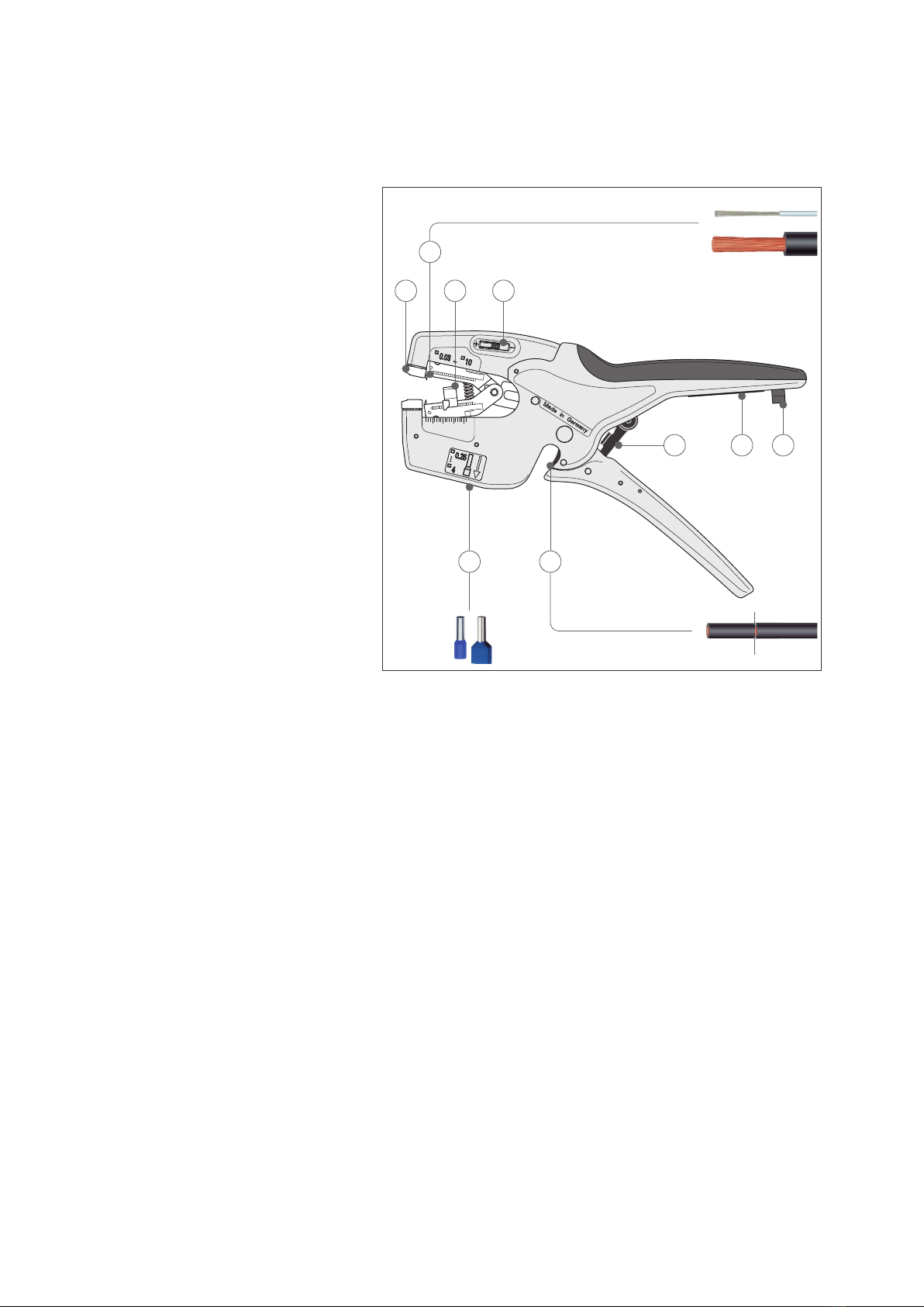
The tool is intended for the following uses:
• Stripping single, multi and ne-stranded conductors from 0.03 to 10 mm²
/ AWG 32 - 8
• Cutting copper and aluminium conductors up to a maximum of 10 mm²
• Crimping single and Twin wire ferrules
The tool must not be used for the following applications:
• Cutting steel
Any use beyond the intended purpose or any unauthorized modication shall
be considered improper. The operator shall be liable for damages resulting
from improper use.
Intended use also includes adhering to these operating instructions.They must
be read in full before use.
Warning!
Warning: Sharp blades!
Handling sharp blades is dangerous. For this reason, make sure to handle
your tools with care when working.

DESiGN aND fuNCTiON
5 Status: 17.05.22
3 Design and function
3.1 Design
510 15 20
0,03 – 10
< 100,25 - 4 /
2 x 2,5
2
1 43
6 5
987
Structure of KNIPEX NexStrip®
1 Clamping jaws for cables/conductors
2 Knife for stripping
3 Adjustable feed stop (3.0 to 17.0 mm)
4 Fine adjustment to adjust the knife’s cutting depth for special materials or
temperature conditions (zero position in the middle)
5 Wire cutter for Cu and Al conductors (max. 10.0 mm²)
6 Crimping point for wire ferrules (square crimp with metal crimping jaws)
Single wire ferrules: 0.25 – 4.0 mm²
Twin wire ferrules: 2 x 2.5 mm²
7 Automatic lock with emergency release
8 Labelling eld for customisation (on the inside of the handle)
9 Tether attachment point for attaching a fall protection device
3.2 Function
The KNIPEX NexStrip®is used for cutting and stripping single, multi and
ne-stranded conductors.
Loose single and Twin wire ferrules are crimped using a square crimp.

OpEraTiON
6 Status: 17.05.22
4 Operation
4.1 Cutting cables
1.
< 10 mm
2
2.
Cutting cables
1. Insert the end of the cable to be cut between the two blades of the
wire cutter.
2. Firmly press the two handles together.
4.2 Stripping cables (with single, multi and ne-stranded
conductors)
»Set the feed stop to the required length (3 to 17 mm).
»Insert the end of the cable into the holder.
»Firmly press the two handles together. The automatic lock is not released
again until the handles have been fully pressed together.
2.
1.
0,03 - 10 mm
2
3.
Stripping single conductors
»Pull the stripped cable out of the holder.
Note:
When the feed stop is removed, the
cable can be stripped to a maximum
length of 20 mm.

OpEraTiON
7 Status: 17.05.22
4.2.1 Fine adjustment of the knife
For insulation materials that are difcult to work with or if there are special
temperature conditions, it may be necessary to adjust the cutting depth.
»Push the ne adjustment slider in the “+” or “-” direction to individually
adjust the knife’s cutting depth.
Readjusting the cutting depth

OpEraTiON
8 Status: 17.05.22
4.3 Crimping wire ferrules
Loose single or Twin wire ferrules can be crimped to cables using the crimp-
ing die on the underside of the tool. The square crimp ensures optimal con-
tact in the clamp.
0,25 - 4,0
2 x 2,5
1.
2.
Crimping wire ferrules
1. Insert the wire ferrule and the cable into the crimping die from below.
2. Firmly press the two handles together. In order to ensure consistently
high crimping quality, the automatic lock is not released again until the
handles have been fully pressed together.
4.3.1 Emergency release of automatic lock
Unlocking automatic lock
If necessary, the automatic lock can be unlocked manually.
»Use a small screwdriver to press the release pin on the inside of the
lower handle.

MaiNTENaNCE
9 Status: 17.05.22
5 Maintenance
5.1 Changing the feed stop
Replacing the feed stop
1. Press the feed stop together lightly and pull it off the guide.
2. Place the new feed stop on the guide so that it clicks into place.
3. Check if the feed stop can be put into different settings.

TEChNiCal DaTa
10 Status: 17.05.22
6 Technical data
Technical data Unit
Item number KNIPEX NexStrip®–12 72 190
Item number spare blades block –12 49 21
Item number spare length stop –12 49 23
Length mm 195
Weight g166
Material body –Glass bre reinforced plastic
Material blade –Special tool steel,
oil-hardened
Capacity, cutting mm² 0.03 ... 10.0
Capacity, stripping mm² 0.03 ... 10.0
Capacity, square
compression
mm² Single wire ferrules:
0.25 – 4.0 mm²
Twin wire ferrules:
to 2 x 2.5 mm²
7 Disposal
The tool can be disposed of as household waste.

11 Status: 17.05.22

KNIPEX-Werk
C. Gustav Putsch KG
42337 Wuppertal
Tel.: +49 202 – 47 94-0
Fax: +49 202 – 47 74 94
www.knipex.com
This manual suits for next models
1
Table of contents
Other KNIPEX Power Tools manuals