KNOVA KN BTS-10N User manual

KN BTS-10N
Table saw with stand
Sierra de mesa para madera con base10
”
(254 mm)

1
Product specications ......................................................... 1
Warning .............................................................................. 1
Symbols .............................................................................. 1
Power tool safety ................................................................ 2
Table saw safety ................................................................. 3
Electrical requirements and safety ..................................... 4
Preparation ......................................................................... 5
Carton contents .................................................................. 6
Know your table saw ......................................................... 7
Glossary of terms .............................................................. 8
Assembly and adjustments ............................................... 9
Operation .......................................................................... 16
Maintenance ..................................................................... 21
Troubleshooting guide ....................................................... 22
Push stick pattern ............................................................. 23
Parts list ............................................................................ 24
Exploded view .................................................................... 25
Parts list and exploded view stand .................................... 26
Parts list and exploded view motor ................................... 27
PRODUCT SPECIFICATIONS
MOTOR
Type: Universal
Amps: 13
Voltage: 120
TABLE OF CONTENTS
WARNINGS
Some dust created by power sanding, sawing, grinding, drilling and other construction activities contains
chemicals known to the state of California to cause cancer, birth defects or other reproductive harm. Some examples
of these chemicals are:
• Lead from lead-based paints,
• Crystalline silica from bricks and cement and other masonry products, and
• Arsenic and chromium from chemically-treated lumber.
Your risk from these exposures varies, depending on how often you do this type of work. To reduce your exposure to these
chemicals work in a well ventilated area, and work with approved safety equipment, such as those dust masks that are spe-
cially designed to ter out microscopic particles.
Avoid prolonged contact with dust from power sanding, sawing, grinding, drilling, and other construction activities. Wear pro-
tective clothing and wash exposed areas with soap and water. Allowing dust to get into your mouth, eyes, or lay on the skin
may promote absorption of harmful chemicals.
WARNING
SYMBOLS
WARNING ICONS
Your power tool and its Instruction Manual may contain “WARNING ICONS” (a picture symbol intended to alert you to, and/or
instruct you how to avoid, a potentially hazardous condition). Understanding and heeding these symbols will help you operate
your tool better a. safer. Shown below are some of the symbols you may see.
SAFETY ALERT: Precautions that involve your safety.
PROHIBITION
WEAR EYE PROTECTION: Always wear safety
goggles or safety glasses with side shields.
READ AND UNDERTAND INSTRUCTION MANUAL:
To reduce the risk of injury, user and all bystanders
must read and understand the instruction manual before
using this product.
KEEP HANDS AWAY FROM BLADE: Failure to keep
your hands away from the blade will result in serious
personal injury.
SUPPORT AND CLAMP WORK
DANGER
DANGER: Indicates an inminently hazardous
situation which, if not avoided, will result in death or
serious injury.
WARNING
WARNING: Indicates a potentially hazardous
situation which, if not avoided, could result in dead or
serious injury.
CAUTION
CAUTION: Indicates a potentially hazardous
situation which, if not avoided, may result in minor or
moderate injury.
CAUTION
CAUTION: Used without the safety alert symbol indi-
cates a potentially hazardous situation which, if not avoided,
may result in property damage.
Hz: 60
RPM (no load): 5000
Overload Protection: YES
SAW
Blade Size: 10 in.
Blade Arbor Size: 5/8 in.
Max. Cut Depth at 90°: 3 in.
Max. Cut Depth at 45°: 2-1/2 in.
Max. Dado Cut Width: 1/2 in.
Max. Dado Blade Diameter: 6 in.
WEAR RESPIRATORY AND HEARING PROTEC-
TION: Always wear respiratory and hearing protection.

2
GENERAL SAFETY INSTRUCTIONS BEFORE USING THIS
POWER TOOL
Safety is a combination of common sense, staying alert and
knowing how to use your power tool.
POWER TOOL SAFETY
WARNING
To avoid mistakes that could cause serious
injury, do not plug the tool in until you have read and
understood the following.
1. READ and become familiar with the entire
Instruction Manual. LEARN the tool’s application,
limitations and possible hazards.
2. KEEP GUARDS IN PLACE and in working order.
3. REMOVE ADJUSTING KEYS AND WRENCHES. Form
the habit of checking to see that keys and adjusting
wrenches are removed from the tool before turning it ON.
4. KEEP WORK AREA CLEAN. Cluttered areas and benches
invite accidents.
5. DO NOT USE IN DANGEROUS ENVIRONMENTS. Do
not use power tools in damp locations, or expose them to
rain or snow. Keep work area well lit.
6. KEEP CHILDREN AWAY. All visitors and bystanders
should be kept a safe distance from work area.
7. MAKE WORKSHOP CHILD PROOF with padlocks,
master switches or by removing starter keys.
8. DO NOT FORCE THE TOOL. It will do the job better and
safer at the rate for which it was designed.
9. USE THE RIGHT TOOL. Do not force the tool or an
attachment to do a job for which it was not designed.
10. USE PROPER EXTENSION CORDS. Make sure your
extension cord is in good condition. When using an
extension cord, make sure to use one heavy enough to
carry the current your product will draw. An undersized
cord will result in a drop in line voltage and in loss of
power which will cause the tool to overheat. The table on
page 5 shows the correct size to use depending on cord
length and nameplate ampere rating. If in doubt, use the
next heavier gauge. The smaller the gauge number, the
heavier the cord.
11. WEAR PROPER APPAREL. Do not wear loose clothing,
gloves, necktie, rings, bracelets or other jewelry which
may get caught in moving pads. Nonslip footwear is
recommended. Wear protective hair covering to contain
long hair.
12. ALWAYS WEAR EYE PROTECTION. Any power
tool can throw foreign objects into the eyes and
could cause permanent eye damage. ALWAYS
wear Safety Goggles (not glasses) that comply
with ANSI Safety standard Z87.1. Everyday
eyeglasses have only impact–resistant lenses.
They ARE NOT safety glasses.
13. WEAR A FACE MASK OR DUST MASK. Sawing
operation produces dust.
14. SECURE WORK. Use clamps or a vise to hold work
when practical. It is safer than using your hand
and it frees both hands to operate the tool.
15. DISCONNECT TOOLS FROM POWER SOURCE before
servicing, and when changing accessories such as blades,
bits and cutters.
16. REDUCE THE RISK OF UNINTENTIONAL STARTING.
Make sure switch is in the OFF position before plugging
the tool in.
17. USE RECOMMENDED ACCESSORIES. Consult this
Instruction Manual for recommended accessories. The
use of improper accessories may cause risk of injury
to yourself or others.
18. NEVER STAND ON THE TOOL. Serious injury could
occur if the tool is tipped or if the cutting tool is
unintentionally start.
19. CHECK FOR DAMAGED PARTS. Before further use of
the tool, a guard or other part that is damaged should be
carefully checked to determine that it will operate
properly and perform its intended function – check for
alignment of moving parts, binding of moving parts,
breakage of parts, mounting and any other conditions
that may affect its operation. A guard or other part that is
damaged should be properly repaired or replaced.
20. NEVER LEAVE THE TOOL RUNNING UNATTENDED.
TURN THE POWER “OFF”. Do not walk away from a
running tool until the grinding wheels come to a complete
stop and the tool is unplugged from the power source.
21. DO NOT OVERREACH. Keep proper footing and balance
at all times.
22. MAINTAIN TOOLS WITH CARE. Keep tools sharp and
clean for best and safest performance. Follow
instructions for lubricating and changing accessories.
23. DO NOT use power tool in presence of ammable liquids
or gases.
24. DO NOT operate the tool under the inuence of any
drugs, alcohol or medication that could affect your ability
to use the tool properly.
25. WARNING: Dust generated from certain materials can
be hazardous to your health. Always operate tool in
well-ventilated area and provide for proper dust removal.
NOTE: Glasses or goggles not in compliance with ANSI Z87.1
could seriously injure you when they break.
26. WEAR HEARING PROTECTION to reduce the
risk of induced hearing loss.
27. IF THE POWER CORD IS DAMAGED DO NOT USE THE
TOOL. Have the cord replaced only by the manufacturer
or by an authorized service center or electrician.
28. MAKE SURE THE WORK AREA HAS AMPLE LIGHTING
to see the work and that no obstructions will interfere
with safe operation BEFORE performing any work using
the saw.

3
TABLE SAW SAFETY
1. ALWAYS USE SAW BLADE GUARD, riving knife and
anti-kickback pawls for every through–sawing operation.
Through–sawing operations are those in which the blade
cuts completely through the workpiece when ripping or
crosscutting. Always be sure blade guard is tightened
securely.
2. ALWAYS HOLD WORKPIECE FIRMLY against the miter
gauge or rip fence.
3. ALWAYS USE a push stick or push block, especially when
ripping narrow stock. Refer to ripping instructions in this
Instruction Manual where the push stick is covered in
detail. A pattern for making your own push stick is
included on page 23.
4. NEVER PERFORM ANY OPERATION FREEHAND, which
means can using hands to support the workpiece, but
always use either the fence OR the miter gauge to
position and guide the workpiece.
DANGER
5. NEVER STAND or have any part of your body in
line with the path of the saw blade. Keep your
hands out of the saw blade path.
FREEHAND CUTTING IS THE MAJOR
CAUSE OF KICKBACK AND FINGER/ HAND
AMPUTATIONS. NEVER USE THE MITER GAUGE
AND FENCE SIMULTANEOUSLY.
6. NEVER REACH behind or over the cutting tool for
any reason.
7. REMOVE the rip fence when crosscutting.
8. DO NOT USE a molding head with this saw.
9. FEED WORK INTO THE BLADE against the direction
of rotation only.
10. NEVER use the rip fence as a cut-off gauge when
crosscutting.
11. NEVER ATTEMPT TO FREE A STALLED SAW BLADE
without rst turning the saw OFF. Turn power switch OFF
immediately to prevent motor damage.
12. PROVIDE ADEQUATE SUPPORT to the rear and the
sides of the saw table for long or wide workpieces.
13. AVOID KICKBACKS (work thrown back towards you) by
keeping the blade sharp, the rip fence parallel to the saw
blade and by keeping the splitter, anti-kickback pawls and
guards in place, aligned and functioning. Do not release
work before passing it completely beyond the saw blade.
Do not rip work that is twisted, warped or does not have
a straight edge to guide it along the fence. Do not attempt
to reverse out of a cut with the blade running.
14. AVOID AWKWARD OPERATIONS and hand positions
where a sudden slip could cause your hand to move into
the saw blade.
15. NEVER USE SOLVENTS to clean plastic parts. Solvents
could possibly dissolve or otherwise damage the material.
Only a soft damp cloth should be used to clean plastic
parts.
16. MOUNT your table saw on a bench or stand before
performing any cutting operations. Refer to ASSEMBLY
AND ADJUSTMENT on page 9.
17. NEVER CUT METALS or masonry products with this tool.
This table saw is designed for use on wood and woodlike
products only.
18. ALWAYS USE IN A WELL VENTILATED AREA. Remove
sawdust frequently. Clean out sawdust from the interior
of the saw to prevent a potential re hazard.
19.
NEVER LEAVE THE SAW RUNNING UNATTENDED. Do
not leave the saw until the blade comes to a complete stop.
20.
For proper operation follow the instructions in this
Instruction Manual entitled ASSEMBLY AND
ADJUSTMENTS (Page 9). NOTE: On machines with no
stand or if stand is not being used, a hole approximately
11 in. square must be cut under saw to allow sawdust to
fall through. Failure to provide sawdust fall-through and
removal hole will allow sawdust to build up in the motor
area resulting in a re hazard and potential motor damage.
21. USE ONLY saw blades recommended with the warning
that the riving knife shall not be thicker than the width of
the groove cut by the saw blade and not thinner than the
body of the saw blade.
22.
USE PUSH-STICK OR PUSH BLOCK to feed the workpiece
past the saw blade. The push-stick or push block should
always be stored with the machine when not in use.
23. DIRECTION OF FEED. Feed workpiece into a blade or
cutter against the direction of rotation of the blade or
cutter only. Never feed material from the back of the saw
as the blade can launch the workpiece at great velocity
across the tabletop.
24. NEVER OPERATE THE SAW ON THE FLOOR.
25. DOUBLE CHECK ALL SETUPS. Make sure the blade is
tight and not making contact with saw or workpiece
before connecting to power supply. Make sure the table
insert and all guards are tight and in place.
26. NEVER ATTEMPT TO PLUNGE CUT INTO A
WORKPIECE by placing it on top of the spinning blade.
The workpiece will kickback.
27. USE THE PROPER TABLE INSERT FOR THE WIDTH
AND DIAMETER OF THE DADO BLADE. Be sure to
check that the blade does not contact the insert before
plugging in and turn on the saw. Never perform bevel
cuts with the dado blade.
28. NEVER GANG CROSSCUT, lining up more than one
workpiece in front of the blade (stacked vertically, or
horizontally outward of the table) and then pushing thru saw
blade. The blade could pick up one or more pieces and
cause a binding or loss of control and possible injury.
29. MAKE SURE THE TABLE INSERT IS FLUSH OR
SLIGHTLY BELOW THE TABLE SURFACE on all sides
except the rear. NEVER operate the saw unless the
proper insert is installed.
30. FOLLOW ALL SAFETY INSTRUCTION LABELS THAT
APPEAR ON THE FRONT OR SIDE OF YOUR TABLE
SAW.

TABLE SAW SAFETY
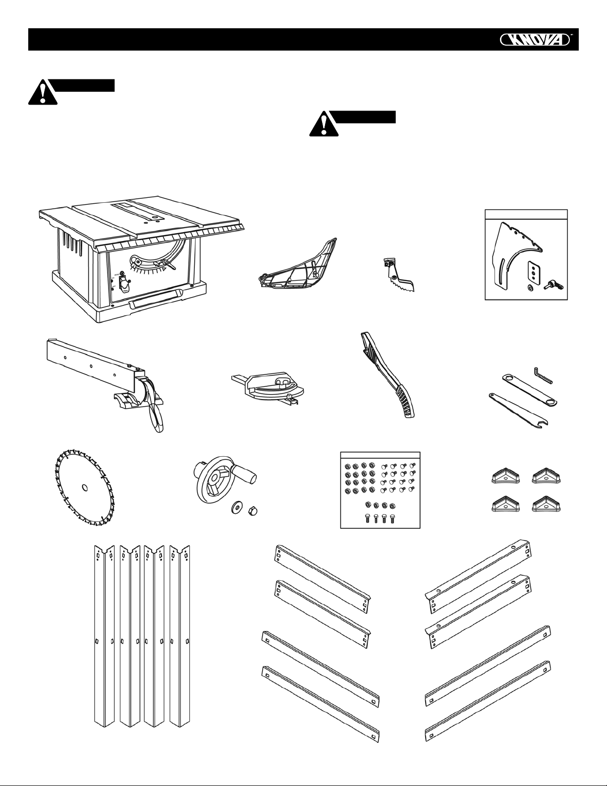
SAW BLADE GUARD ASSEMBLY, ANTIKICKBACK
ASSEMBLY AND RIVING KNIFE
Your table saw is equipped with a blade guard assembly, anti-
kickback assembly and riving knife that covers the blade and
reduces the possibility of accidental blade contact. The riving
knife is a at plate that ts into the cut made by the saw blade
and effectively ghts kickback by lessening the tendency of
the blade to bind in the cut.
The blade guard assembly and antikickback assembly can
only be used when making through cuts that sever the wood.
When making rabbets and other cuts that make non through
cuts, the blade guard assembly and anti-kickback assembly
must be removed and riving knife lowered to the non through
cut position marked on the riving knife. Two anti-kickback
pawls are located on the sides of the riving knife that allow
the wood to pass through the blade in the cutting direction
but reduce the possibility of the material being thrown back-
wards toward the operator.
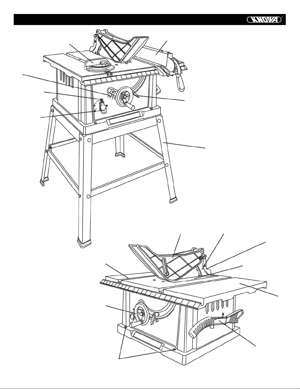
Use all components of the guarding system (blade guard
assembly, riving knife and antikickback assembly) for every
operation for which they can be used including all through
cutting.
If you elect not to use any of these components for a particu-
lar application exercise additional caution regarding control
of the workpiece, the use of push sticks, the position of your
hands relative to the blade, the use of safety glasses, the
means to avoid kickback and all other warnings contained in
this manual and on the saw itself.
Replace the guarding systems as soon as you return to thru-
cutting operations. Keep the guard assembly in working order.
KICKBACKS
KICKBACKS: Kickbacks can cause serious injury. A kickback
occurs when a part of the workpiece binds between the saw
blade and the rip fence, or other xed object, and rises from
the table and is thrown toward the operator. Kickbacks can be
avoided by attention to the following conditions.
How to avoid them and protect yourself from possible injury:
a. Be certain that the rip fence is parallel to the saw blade.
b. Do not rip by applying the feed force to the section of the
workpiece that will become the cut-off (free) piece. Feed
force when ripping should always be applied between the
saw blade and the fence; use a push stick for narrow
work, 6 in. (152 mm) wide or less.
c. Keep saw blade guard assembly, riving knife and anti-kick-
back assembly in place and operating properly. If
anti-kickback assembly is not operational, return your
unit to the nearest authorized service center for repair.
The riving knife must be in alignment with the saw blade
and the anti-kickback assembly must stop a kickback once
it has started. Check their action before ripping by
pushing the wood under the anti-kickback assembly.
The teeth must prevent the wood from being pulled
toward the front of the saw.
d. Plastic and composite (like hardboard) materials may be
cut on your saw. However, since these are usually quite
hard and slippery, the anti-kickback pawls may not stop a
kickback. Therefore, be especially attentive to following
proper set up and cutting procedures for ripping.
e. Use saw blade guard assembly, anti-kickback assembly
and riving knife for every operation for which it can be
used, including all through-sawing.
f. Push the workpiece past the saw blade prior to release.
g. Never rip a workpiece that is twisted or warped, or does
not have a straight edge to guide along the fence.
h. Never saw a large workpiece that cannot be controlled.
i. Never use the fence as a guide or length stop when
crosscutting.
j. Never saw a workpiece with loose knots, aws, nails or
other foreign objects.
k. Never rip a workpiece shorter than 10 in. (254 mm).
l. NEVER use a dull blade – replace or have resharpened.
m. NEVER use a rip fence and miter gauge together.
n. Keep hands out of saw blade.
ELECTRICAL REQUIREMENTS AND SAFETY
GROUNDING INSTRUCTIONS
IN THE EVENT OF A MALFUNCTION OR BREAKDOWN,
grounding provides a path of least resistance for electric
currents and reduces the risk of electric shock. This tool is
equipped with an electrical cord that has an equipment-
grounding conductor and a grounding plug. The plug must be
plugged into a matching receptacle that is properly installed
and grounded in accordance with all local codes and ordinances.
DO NOT MODIFY THE PLUG PROVIDED. If it will not t the
receptacle, have the proper receptacle installed by a qualied
electrician.
IMPROPER CONNECTION of the equipment grounding con-
ductor can result in risk of electric shock. The conductor with
the green insulation (with or without yellow stripes) is the
equipment grounding conductor. If repair or replacement of
the electrical cord or plug is necessary, do not connect the
equipment grounding conductor to a live terminal.
CHECK with a qualied electrician or service person if you do
not completely understand the grounding instructions, or if
you are not certain the tool is properly grounded.
USE only three-wire extension cords that have three-pronged
grounding plugs with three-pole receptacles that accept the
tool’s plug. Repair or replace damaged or worn cords imme-
diately.
GUIDELINES FOR EXTENSION CORDS
USE THE PROPER EXTENSION CORD.
Make sure your extension cord is in good condition. Use an
extension cord heavy enough to carry the current your pro-
duct will draw. An undersized cord will cause a drop in line
voltage resulting in loss of power, overheating and burning
out of the motor.
The table on page 5 shows the correct size to use depending
on cord length and nameplate ampere rating. If in doubt, use
the next heavier gauge. The smaller the
gauge number, the heavier the cord.
Make sure your extension cord is properly wired and in good
condition. Always replace a damaged extension cord or have
it repaired by a qualied technician before using it. Protect
your extension cords from sharp objects, excessive heat and
damp or wet areas.
4

ELECTRICAL REQUIREMENTS AND SAFETY
Use a separate electrical circuit for your tool. This circuit must
not be less than #12 wire with a 20 A time-lag fuse or a #14
wire with a 15 A time-lag fuse.
NOTE: When using an extension cord on a circuit with a #14
wire, the extension cord must not exceed 25 feet in length.
Before connecting the motor to the power line, make sure the
switch is in the off position and the electric current is rated
the same as the current stamped on the motor nameplate.
Running at a lower voltage will damage the motor. This tool is
intended for use on a circuit that has a receptacle like the one
illustrated in Fig. A.
Fig. A shows a three-pronged electrical plug and receptacle
that has a grounding conductor. If a properly grounded recep-
tacle is not available, an adapter (sold separately)
(Fig. B) can be used to temporarily connect this plug to a
twocontact grounded receptacle. The adapter (Fig. B) has a
rigid lug extending from it that MUST be connected to a per-
manent earth ground, such as a properly grounded receptacle
box.
WARNING
Never remove the grounding prong from
the power cord. If damaged, discontinue use of unit
and contact customer service for a replacement cord.
Three-Pronged Plug
Fig. A
Grounding Prong
Properly Grounded
Three-Pronged Receptacle
Fig. B Grounding Lug
Adapter
Make sure this
is connected
to a known
ground.
Two-Pronged
Receptacle
WARNING
• In all cases, make certain the
receptacle is properly grounded. If you are not sure,
have a qualied electrician check the receptacle.
• This tool is for indoor use only. Do not expose to rain or
use in damp locations.
• This tool must be grounded while in use to protect the
operator from electric shock.
MINIMUM GAUGE FOR EXTENSION CORDS (AWG)
(When using 120 volts only)
Ampere Rating Total length of Cord
More than
Not more than
25ft. 50ft. 100ft. 150ft.
0 6 18 16 16 14
6 10 18 16 14 12
10 12 16 16 14 12
12 16 14 12
Not Recommended
PREPARATION
Before beginning assembly or operation of the product, make
sure all parts are present.
Compare parts with package contents list and diagram above.
If any part is missing or damaged, do not attempt to assem-
ble, install or operate the product. Contact customer service
for replacement parts.
• Estimated Assembly Time: 40-60 minutes
• Tools Required for Assembly and Adjustment:
Supplied
NOT Supplied
RECOMMENDED
ACCESSORIES
Use only the recommended
accessories with this table
saw. Follow the instructions
that are supplied with these
accessories.
308K DADO INSERT PLATE
Blade Wrench
Blade Wrench
4 mm Hex Wrench
Adjustable Wrench
and/or 13 mm Wrench Phillips Screwdriver
Slotted Screwdriver
5, 6 mm Hex Wrench
Combination Square
CAUTION
• Do
not use adjustable or
wobble-type dado’s.
Use stackable dado
sets only. Maximum
dado width is 1/2 in.
• Do not use a dado with a diameter greater than 6 in.
• Do not attempt to use a dado set without the proper dado
insert plate secured in place.
• Do not use a molding head set with this saw.
• Do not modify this saw or use accessories not
recommended by customer service.
5

6
CARTON CONTENTS
UNPACKING YOUR TABLE SAW
To avoid injury from unexpected starting
or electrical shock, do not plug the power cord into a
source of power during unpacking and assembly. This
cord must remain unplugged whenever you are work-
ing on the saw.
CAUTION
1. Remove the table saw from the carton.
2. Place the saw on a secure stationary work surface.
3. Separate all parts from the packing material. Check each
one with the illustration on below to make certain all
items are accounted for before discarding any packing
material.
If any part is missing or damaged, do not
attempt to assemble the table saw, or plug in the pow-
er cord until the missing or damaged part is correctly
replaced. To avoid electric shock, use only identical
replacement parts when servicing double insulated
tools.
CAUTION
Table Saw
Assembly
Blade Guard
Anti-kickback
Pawl
Riving Knife
Assembly
Puch Stick
(located on
saw base) Blade Wrenches
(2) & Hex Key
Miter Gauge
Assembly
Rip Fence
Saw Blade Handwheel
Assembly
Stand Parts
Hardware Bag
Leg Pads
Top Long Support
Brackets
Top Short Support
Brackets
Bottom Short
Support Brackets
Bottom Long
Support Brackets
Legs

7
KNOW YOUR TABLE SAW
Miter Gauge
Blade Tilt
Pointer & Scale
Overload Reset
Switch
ON/OFF
Switch Key
Stand
Blade Bevel
Lock Handle
Rip Fence
Blade Guard
Miter Gauge
Slot
Blade
Elevation/Tilting
Handwheel
Mounting Holes
Riving Knife
Push Stick
Table
Anti-kickback Pawls
Table Insert

8
GLOSSARY OF TERMS
ANTI-KICKBACK PAWLS – To prevent the workpiece being
kicked upward or back toward the front of the table saw by
the spinning blade.
ARBOR – The shaft on which the blade or dado is mounted.
BEVEL CUT – An angle cut made through the face of the
workpiece.
BLADE BEVEL SCALE – To measure if the angle of the blade
is tilted when set for a bevel cut.
BLADE ELEVATION AND TILTING HANDWHEEL – To raise
and lower the blade or tilt the blade to the angle between 0º
and 45º for bevel cuts.
BLADE GUARD – A clear plastic cover that positions over the
blade while cutting.
COMPOUND CUT – A simultaneous bevel and miter cut.
CROSSCUT – A cut made across the width of the workpiece.
DADO – Special cutting blades that are used to cut grooves
in a workpiece.
FEATHERBOARD – When ripping a workpiece on your table
saw, this keeps it rmly and safely against the rip fence. It
also helps prevent chatter, gouging, and dangerous kickback.
FREEHAND – Performing a cut without using a rip fence, mi-
ter gauge, hold down or other proper device to prevent the
workpiece from twisting during the cutting operation.
GUM – A sticky sap from wood products.
HEEL – Misalignment of the blade.
JAMB NUT – Nut used to lock another nut in place on a
threaded rod or bolt.
KERF – The amount of material removed by the blade cut.
KICKBACK– Occurs when the saw blade binds in the cut and
violently thrusts the workpiece back toward the operator.
LEADING END – The end of the workpiece which, during a rip
type operation is pushed into the cutting tool rst.
MITER CUT – An angle cut made across the width of the
workpiece.
MITER GAUGE – A guide used for crosscutting operations
that slides in the table top channels (grooves) located on ei-
ther side of the blade. It helps make accurate straight or angle
crosscuts.
NON-THROUGH SAWING – refers to any cut that does not
completely cut through the workpiece.
OVERLOAD RESET SWITCH – Protects the motor if it over-
loads during operation, provides a way to restart the saw.
PUSH STICK – Used to push workpieces when performing
ripping operations.
PUSH BLOCK – Used for ripping operation when the work-
piece is too narrow to use a push stick. Always use a push
block for rip widths less than 2 in.
RABBET – A notch in the edge of a workpiece. Also called an
edge dado.
RESAWING – Flipping material to make a cut the saw is not
capable of making in one pass.
WARNING
Resawing IS NOT recommended.
REVOLUTIONS PER MINUTE (RPM) – The number of turns
completed by a spinning object in one minute.
RIP FENCE – A guide used for rip cutting which allows the
workpiece to cut straight.
RIPPING – Cutting with the grain of the wood or along the
length of the workpiece.
RIVING KNIFE – A metal piece of the guard assembly located
behind and moves with the blade. Slightly thinner than the
saw blade, it helps keep the kerf open and prevents kickback.
SAW BLADE PATH – The area of the workpiece or table top
directly in line with the travel of the blade or the part of the
workpiece that will be cut.
SET – The distance between two saw blade tips, bent outward
in opposite directions to each other. The further apart the tips
are, the greater the set.
TABLE INSERT – Insert that is removed from the table to
install / remove blades. It is also removed for dado cutting.
When dado cutting, a dado insert plate must be used.
THROUGH SAWING – Making a cut completely through the
length or width of a workpiece.
WORKPIECE – Material to be cut.
NOTE: Blade guard assembly is removed for purposes of
illustration only.
Saw blade path
Leading edge
Kerf
Surface
Workpiece
Trailing edge

ASSEMBLY AND ADJUSTMENT
9
ASSEMBLING STAND (Fig. 1)
1. Unpack all parts and group by type and size. Refer to the
Carton Contents.
2. Attach one long top support (5) to top of leg (8) using one
bolt (1) and nut (2). Align the detents (9) in stand leg with
top supports to ensure proper t. (Fig. 1-A)
NOTE: Do not tighten bolts until stand is properly aligned
(see step # 8 before tightening).
3. Attach other end of long top support to top of another leg
using one bolt and nut.
4. Attach one long bottom support (7) to center of each leg
using bolt (1) and nut (2). This completes the front frame
section.
5. Assemble rear frame section in exactly the same manner.
6. Join front and rear frame assemblies using two short top
supports (4) and two short bottom supports (6), bolts and
nuts.
7. Insert foot pad (3) onto bottom of leg. Repeat for each leg.
8. Place stand on level surface and adjust so all legs are
contacting the oor and are at similar angles to the oor.
Tighten all bolts using a 13 mm wrench.
NOTE: Stand should not rock after all bolts are tightened.
Front
Fig. 1-A
9
1
2
4
3
5
4
6
3
8
7
5
2
1
ASSEMBLING TABLE SAW TO STAND (Fig. 2)
Do not operate this machine directly on
the oor without using the stand. This is a very
dangerous position.
CAUTION
1. Place the saw (1) on the stand (2). Line up the four holes
(3) on the saw base with the holes in the stand top.
NOTE: Make sure front of stand and front of saw are facing
the same direction.
2. Fasten saw to stand using four bolts (4) and nuts (5).
3. Tighten all four nuts with two 13 mm wrenches.
NOTE: DO NOT OVERTIGHTEN NUTS HOLDING SAW TO
STAND. THIS WILL DAMAGE THE SAW BASE.
Fig. 1
Fig. 2
SAW MOUNTED TO WORK SURFACE (Fig. 3)
1. If the leg set will not be used, the saw must be properly
secured to a sturdy workbench using the four mounting
holes at the base of the saw.
2. The surface of the table where the saw is to be mounted
must have a hole large enough to facilitate sawdust
fall-through and removal.
3. Square the saw on the mounting surface and mark the
location of the four 3/8 in. mounting holes (1).
4. Drill 3/8 in. hole into the mounting surface.
5. Mark an 11 in. square (2) centred between the four
mounting holes (1).
6. Cut out and remove the square.
7. This opening will allow sawdust to fall through
the saw base.
8. Place the saw on the work surface, and align the mounting
holes of the saw with those drilled through the surface.
9. Fasten the saw to the work surface.
Do not operate this machine on the oor.
This is very dangerous and may cause serious injury.
CAUTION

ASSEMBLY AND ADJUSTMENT
10
Fig. 3
2
1
Square
cutout
ATTACHING THE BLADE ELEVATION/ TILTING
HANDWHEEL (Fig. 4)
1. Attach the blade elevation handwheel (1) to the elevation
rod (2) at the front of the saw. Make sure the pin (4) is
inserted in the slot (3) in the back of the handwheel hub.
2. Attach and tighten the crown nut (5) and washer (6) with
a 13 mm wrench.
Failure to provide the sawdust fallthrough
hole for use of the saw when mounted to a work
surface and not the stand will cause sawdust to build
up in the motor area, which may result in re or cause
motor damage.
Always keep your work area clean, uncluttered and
well lit.
CAUTION
Fig. 4 4
1
8
2
3
15
6
1
rear view front view
INSTALLING THE BLADE (Fig. 5, 6, 7)
• To avoid injury from an accidental start, make sure the
switch is in the OFF position and the plug is not connected
to the power source outlet.
1. Remove the table insert (1) by snapping out from the hole
(8). Raise the blade arbor to the maximum height by turning
the blade elevation handwheel clockwise.
Fig. 5
2. Remove the arbor nut (2) and outer blade ange (3).
(Fig. 6)
3. Place the blade onto the arbor (4) with the blade teeth
pointing forward to the front of the saw. (Fig. 6)
NOTE: Leave the plastic strip around the saw blade at this
time. Remove before using the saw for the rst time.
4. Make sure the blade ts ush against the inner ange.
5. Clean the outer blade ange (3) and install it onto the arbor
(4) and against the blade. (Fig. 6)
6. Thread the arbor nut (2) onto the arbor, making sure the
at side of the nut is against the blade ange, then
handtighten. (Fig. 6)
7. To tighten the arbor nut (2), place the open-end wrench (6)
on the ats of the saw arbor (5) to keep the arbor from
turning. (Fig. 7)
8. Place the box-end wrench (7) on the arbor nut (2) and turn
clockwise (to the rear of the saw table). (Fig. 7)
9. Do not replace insert until after the next step of adding
the riving knife assembly.
4
32
5
Fig. 6
Fig. 7
6
3
2
7
REMOVING THE BLADE (Fig. 5, 7)
To avoid injury from an accidental start,
make sure the switch is in the OFF position and the plug
is disconnected from the power source outlet.
CAUTION

ASSEMBLY AND ADJUSTMENT
11
1. Remove the table insert by snapping out from the hole (8).
(Fig. 5)
2. Raise the blade to the maximum height by turning the blade
elevation handwheel clockwise.
3. Adjust the blade to the 90° vertical position by unlocking
the blade tilting lock knob, push in the blade elevation
wheel and turn the bevel tilting handwheel
counterclockwise, and then lock into position.
4. Place the box-end wrench (7) on the arbor nut (2). (Fig. 7)
5. Place the open-end wrench (6) on the ats of the saw arbor
to keep the arbor from turning and loosen the arbor nut (2).
(Fig. 7)
6. Then remove the blade. Clean but do not remove the inner
blade ange before reassembling the blade.
RIVING KNIFE ASSEMBLY
• To avoid injury from an accidental start,
make sure the switch is in the OFF position and the plug
is disconnected from the power source outlet.
• Never operate this saw without the riving knife in
the correct position.
CAUTION
INSTALLING THE RIVING KNIFE ASSEMBLY (Fig. 8)
NOTE: The table insert should be removed and the blade
raised to its highest position before proceeding.
1. Loosen the blade lock handle (1). Turn and move the
handwheel (2) to 45° on the bevel scale.
2. Tighten the blade lock handle.
1
2
Fig. 8
3. Place the riving knife (3) on the mounting bracket (4)
located behind the saw blade. The two pins (5) on the
bracket should t into the slot on the riving knife.
4. Make sure the riving knife (3) is in its highest position.
5. Insert the set plate (6) making sure the two outer holes t
into the two pins on the mounting bracket.
6. Insert the washer (7) into the lock lever (8) and insert into
the middle hole the set plate and tighten.
7. Loosen the blade lock handle (1) and return the blade
to 0° and lock.
8. Place the table insert back into position.
• To avoid the lock lever interferring the
table insert, after tighten the riving knife, position the
lock lever pointing downward before using saw.
(Fig. 10) Failure to maintain a level insert can result in
serious injury to the operator.
NOTE: The riving knife has two positions, the high
position for all through cuts and the lower position for
all non-through cuts.
CAUTION
Fig. 9
Fig. 10
3
3
6
7
8
4
5
cavity side face
to lock lever
6
8
ALIGNING THE RIVING KNIFE (Fig. 11)
• To avoid injury from an accidental start,
make sure the switch is in the OFF position and the
plug is disconnected from the power source outlet.
CAUTION
• Never operate this tool without the riving knife in the
correct position.

ASSEMBLY AND ADJUSTMENT
12
• Never operate this tool without the blade guard in place for
all through sawing operations.
• This adjustment was made at the factory, but it should be
rechecked and adjusted if necessary.
1. Remove the table insert and raise the blade to the
maximum height by turning the blade elevation handwheel
clockwise.
2. Remove the blade guard and antikickback pawl assembly.
3. Adjust the blade to the 0° vertical position by unlocking the
blade tilting lock knob and turning the bevel tilting
handwheel counterclockwise, and then lock into position.
4. To see if the blade (1) and riving knife (2) are correctly
aligned, lay a combination square along the side of the
blade and against the riving knife (making sure the square
is between the teeth of the blade).
5. Tilt the blade to the 45° position and check the alignment
again.
NOTE:
• This table saw is provided with a 10 in. diameter blade with
a body thickness of 0.07 in. (1.8 mm) thick with a kerf of
0.10 in. (2.6 mm ).The riving knife is 0.09 in. (2.2 mm) thick.
The blade diameter and the blade body and kerf dimensions
must be properly matched with the riving knife thickness.
• The maximum radial distance between the riving knife and
the toothed rim of the saw blade is 0.12 in. ~ 0.31 in.
(3 mm ~ 8 mm).
• The tip of the riving knife shall not be lower than
0.04 in. ~ 0.2 in. (1 mm ~ 5 mm) from the tooth peak.
• The riving knife is thinner than the width of the kerf
by approximately 1/64 in. (0.4 mm) on each side.
• The blade body must be thinner than the thickness of the
riving knife but the blade kerf must be thicker than
the riving knife.
6. Check the riving knife and blade alignment again at both
0° and 45°.
7. Replace the table insert, blade guard and anti-kickback
pawl assembly.
Fig. 11
2
1
To avoid possible injury and damage to
the workpiece, be sure to INSTALL THE BLADE WITH
THE TEETH POINTING TOWARD THE FRONT OF
TABLE in the direction of the rotation arrow on the
blade guard.
CAUTION
ADDITIONAL BLADE ADJUSTMENTS (Fig. 12)
NOTE: The adjusting mechanism is located above the blade
height adjusting handwheel under the tabletop. If the front
and rear measurements are not the same.
If the blade is partial to right side:
1. Turn the left adjustment screw (2) counterclockwise and
adjust the right side adjustment screw (3) clockwise.
2. Remeasure, as described in steps 4 to 7 in the prior section.
3. When alignment is achieved, turn the left adjustment
screw (2) until it touches the pivot rod (4).
If the blade is partial to left side:
1. Turn the right adjustment screw (3) counterclockwise and
adjust the left side adjustment screw (2) clockwise.
2. Remeasure, as described in steps 4 to 7 in the prior section.
3. When alignment is achieved, turn the right adjustment
screw (3) until it touches the pivot rod (4).
Fig. 12 4
3
2
BLADE GUARD ASSEMBLY
To avoid injury from an accidental start,
make sure the switch is in the OFF position and the
plug is disconnected from the power source outlet.
CAUTION
• When installing the blade guard, cover the blade teeth with
a piece of folded cardboard to protect yourself from
possible injury.
• Never operate this machine without the blade guard in
place for all through sawing operations.
INSTALLING THE BLADE GUARD AND ANTI-KICKBACK
PAWL ASSEMBLY (Fig. 13, 14, 15)
1. Make sure the blade is elevated to its maximum height
and the bevel is set at 0°. Make sure the bevel lock handle
is tight.
2. Take the anti-kickback pawl assembly (1) and locate the
sliding knob, and push the locking knob (2) up. (Fig. 13)
3. Place the front of assembly into the back slot on the riving
knife and push downward. Release the locking knob. Make
sure the locking knob is engaged in the hole and that there
is no movement of the assembly.

Fig. 17
3
1
2
ASSEMBLY AND ADJUSTMENT
13
Fig. 13
1
2
6
3
3
5
4. Take the blade guard
assembly and locate the
sliding locking knob (3) on
the back of assembly.
(Fig. 14)
Fig. 14
Fig. 15
5. Insert the blade guard assembly onto the riving knife so
that the pin (4) engages into slot (5) completely. (Fig. 15)
6. Slide the locking knob (3) up and press the guard assembly
down so that the entire assembly is at on the riving knife.
Release the locking knob (3).
7. Make sure that
the assembly is
locked in place
both in front
and back.
REMOVING THE BLADE GUARD AND ANTI-KICKBACK
PAWL ASSEMBLY (Fig. 13, 14)
To avoid injury from an accidental start,
make sure the switch is in the OFF position and the
plug is disconnected from the power source outlet.
CAUTION
1. With the blade elevation handwheel raise the blade to the
maximum height.
2. Loosen the blade lock handle and then turn the handwheel
to 45° on the bevel scale.
3. Tighten the bevel lock handle.
4. Remove the anti-kickback pawl assembly by pressing up
on the locking knob (2) and lifting the assembly off the
riving knife. (Fig. 13)
5. Remove the blade guard assembly by pressing up on the
locking knob (3) and lifting the assembly off the riving
knife. (Fig. 14)
AVOIDING KICKBACKS (Fig. 16)
(Work thrown back towards you) by keeping the blade sharp,
the rip fence parallel to the saw blade and by keeping the riving
knife, anti-kickback pawls and guards in place, aligned and
functioning. Do not release work before passing it completely
beyond the saw blade. Do not rip work that is twisted, warped
or does not have a straight edge to guide it along the fence.
Do not attempt to reverse out of a cut with the blade running.
Improper riving knife alignment can
cause “kickback” and serious injury.
CAUTION
Anti- kickback
pawl Fig. 16
RIP FENCE (Fig. 17)
1. Lift upward on the rip fence
handle (1) so the rear
holding clamp (2) is
fully extended.
2. Place the rip fence on
the saw table, position
the set plate (3)
under the front
of fence and
then lower
the back of fence
onto the table.
3. Push down on the fence
handle (1) to lock.
RIP FENCE ADJUSTMENT (Fig. 18)
1. The fence (1) is moved by lifting up on the handle (2) and
sliding the fence to the desired location. Pushing down on
the handle locks the fence in position.
2. Position the fence on the right side of the table and along
the edge miter gauge groove.
3. Lock the fence handle. The fence should be parallel with
the miter gauge groove.
4. If adjustment is needed to make the fence parallel to
the groove, do the following:
• Loosen the two bolts (3) and lift up on the handle (2).
• Hold the fence bracket (4) rmly against the front of the
saw table. Move the fence until it is parallel with the miter
gauge groove.

14
ASSEMBLY AND ADJUSTMENT
• Push the handle down and tighten both bolts.
5. If fence is loose when the handle is in the locked
(downward) position, do the following:
•
Move the handle (2) upward and turn the adjusting nut (5)
clockwise until the rear clamp is snug.
NOTE: Over-tightening the adjusting bolts will cause the fence
to come out of alignment.
Failure to properly align fence can cause
“kickback” and serious injury.
CAUTION
6
7Fig. 19
MITER GAUGE
A miter gauge is supplied with your table saw to be used in
the table slot on the each side of the blade. The miter gauge
can be adjusted from 90° to 30° right or left to maintain an
accurate angle for your workpiece.
ADJUSTING THE MITER GAUGE (Fig. 20)
1. Loosen the lock handle (1) to allow the miter body (2) to
rotate freely. Position the miter body at 90° so the positive
detent secures its position. Tighten the lock handle to hold
the miter body in position.
3. To change angles on the miter
gauge, loosen the lock handle
(1) and rotate the miter body
to the desired angle as
indicated by the scale. Secure
in position by tightening
the lock handle.
2
1
3
Fig. 20
ADJUSTING THE TABLE INSERT (Fig. 21)
To avoid serious injury, the table insert
(2) must be level with the table. If the table insert is
not ush with the table, adjust the two bolts (1) with
a 4 mm hex wrench until it is parallel with the table.
CAUTION
NOTE: To raise the insert, turn the hex screws counterclock-
wise. To lower the insert, turn the hex screws clockwise. Do
not remove the insert, adjustments need to be made with the
insert in place to get the proper level.
2
2
1
Fig. 21
ADJUSTING THE 90° AND 45° POSITIVE STOPS
(Fig. 22, 23)
Your saw has positive stops that will quickly position the saw
blade at 90° and 45° to the table. Make adjustments only if
necessary.
90° Stop
1. Disconnect the saw from the power source.
2. Raise the blade to the maximum elevation.
3. Loosen the blade bevel lock handle and move the blade to
the maximum vertical position and tighten the bevel lock
handle.
4. Place a combination square on the table and against the
blade (1) to determine if the blade is 90° to the table.
(Fig. 22)
2. If the pointer (3) requires adjustment, loosen the screw
under the pointer with a screwdriver. Adjust the pointer to
90° on the scale, then rmly tighten the adjustment screw.
5
1
3
42
Fig. 18
RIP FENCE INDICATOR ADJUSTMENT (Fig. 19)
1. The rip fence indicator (6) points to the measurement scale.
The scale shows the distance from the side of the fence to
nearest side of the blade.
2. Measure the actual distance with a rule. If there is a
difference between the measurement and the indicator,
adjust the indicator (6).
3. Loosen the screw (7)
and slide
the indicator
to the correct
measurement
on the scale.
Tighten the
screw and
remeasure
with the rule.

90º
Fig. 22 45º
12
15
ASSEMBLY AND ADJUSTMENT
5. If the blade is not 90° to the table, loosen or tighten
(depending on whether you are increasing or decreasing
the degrees) the hex bolt (3) with a 5 mm hex wrench
until you achieve 90°. (Fig. 23)
6. Loosen the bevel lock handle and reset the blade at the
maximum vertical position, then tighten the bevel lock
handle.
7. Check again to see if the blade is 90° to the table. If not,
repeat step 5.
8. Lastly, check the bevel angle scale. If the pointer does not
read 90°, loosen the screw holding the pointer and move the
pointer so it is accurate at 0° and retighten the pointer screw.
45° Stop
1. Disconnect the saw from the power source.
2. Raise the blade to the maximum elevation.
3. Loosen the blade bevel lock handle and move the blade to
the maximum bevel position (45°) and tighten the bevel lock
handle.
4. Place a combination square on the table and against the
blade (2) to determine if the blade is 45° to the table.
(Fig. 22)
5. If the blade is not 45° to the table, loosen or tighten
(depending on whether you are increasing or decreasing
the degrees) the hex bolt (4) with a 5 mm hex wrench until
you achieve 45°. (Fig. 23)
6. Loosen the bevel lock handle and reset the blade at the
maximum bevel position (45°), then tighten the bevel lock
handle.
7. Check again to see if the blade is 45° to the table. If not,
repeat step 5.
Fig. 23
4
3
BLADE PARALLEL TO THE MITER GAUGE GROOVE (Fig. 24)
This adjustment was made at the factory,
but it should be rechecked and adjusted if necessary.
CAUTION
• Always disconnect plug from the power source when
making any adjustments.
• This adjustment must be correct or accurate cuts can not
be made. Also inaccurate adjustment can result in kickback
and serious personal injury.
1. Remove the safety switch key and unplug the saw.
2. Remove the blade guard for this procedure but reinstall and
realign after adjustment.
3. Raise the blade to the highest position and set at
the 0° angle (90° straight up).
4. Select and mark, with a felt tip marker, a blade tooth having
a “right set” and rotate the blade so the marked tooth is
1/2 in. above the table.
5. Place the combination square base (1) into the right side
miter gauge groove (2).
6. Adjust the rule so it touches the front marked tooth and
lock ruler so it holds its position in the square assembly.
7. Rotate the blade bringing the marked tooth to the rear and
about 1/2 in. above the blade.
8. Carefully slide the combination square to the rear until the
ruler touches the marked tooth.
9. If the ruler touches the marked tooth at the front and rear
position, no adjustment is needed at this time. If not or the
base of the rule is no longer parallel with the edge of the
miter gauge groove, perform adjustment procedure
described in section ADDITIONAL BLADE
ADJUSTMENTS on page 12.
To prevent personal injury:
CAUTION
Fig. 24
2
1
PUSH STICK STORAGE
(Fig. 25)
Attach the metal push-stick
storage bracket (1) into the
provided slots (2) on the
right side of the body shell.
The bracket will snap down
into place. Place the push
stick (3) into the bracket.
Fig. 25
2
3
1

OPERATION
16
BASIC SAW OPERATIONS
RAISE THE BLADE (Fig. 26)
To raise or lower the blade, turn the blade elevation hand-
wheel (1) to the desired blade height, and then tighten the
bevel lock handle (2) to maintain the desired blade height.
TILTING THE BLADE (Fig. 26)
Loosen the bevel lock handle (2), move the handwheel (1) to
the desired angle, then tighten the bevel lock handle.
Fig. 26
2
1
ON/OFF SWITCH (Fig. 27)
The ON / OFF switch has a safety removal key. With the key
removed from the switch, unauthorized and hazardous use by
children and others is minimized.
1. To turn the saw ON, insert the safety switch key (1) into
the slot in the switch (2). Move the switch upward to the
ON position.
2. To turn the saw OFF, move the switch downward.
3. To lock the switch in the OFF position, grasp the end
(or yellow part) of the safety switch key (1), and pull it out.
4. With the safety removal key removed, the switch will not
operate.
5. If the safety removal key is removed while the saw is
running, it can be turned OFF but cannot be restarted
without inserting the switch key (1).
Fig. 27
2
1
3
OVERLOAD PROTECTION (Fig. 27)
This saw has an overload reset button (3) that resets the mo-
tor after it shuts off due to overloading or low voltage. If the
motor stops during operation, turn the ON / OFF switch to
the OFF position. Wait about ve minutes for the motor to
cool, the push the reset button (3) and turn the switch to the
ON position.
To avoid injury, the ON / OFF switch
should be in the OFF position and the plug removed
from the power source while the cool down takes
place, to prevent accidental starting when the reset
button is pushed. Overheating may be caused by mis-
aligned parts or a dull blade or undersized extensing
cord. Inspect your saw for proper setup before using
it again.
CAUTION
CUTTING OPERATIONS
There are two basic types of cuts: ripping and crosscutting.
Ripping is cutting along the length and the grain of the work-
piece. Crosscutting is cutting either across the width or across
the grain of the workpiece. (It is not safe to rip or crosscut
by freehand). Ripping requires the use of the rip fence, and
crosscutting requires the miter gauge.
NEVER USE THE TWO AT THE SAME TIME.
NOTE: Apply a coat of automobile wax to the table. Wipe all
parts thoroughly with a clean dry cloth. This will reduce fric-
tion when pushing the workpiece.
Before using the saw each time, check
the following:
CAUTION
1. The blade is tightened to the arbor.
2. The bevel angle lock knob is tightened.
3. If ripping, make sure the fence is locked into position and
is parallel to the miter gauge groove.
4. The blade guard is in place and working properly.
5. Safety glasses are worn.
The failure to adhere to these common safety rules, and those
printed in the front of this manual, can greatly increase the
likelihood of injury.
RIPPING (Fig. 28, 29)
To prevent serious injury:
CAUTION
• Never use a miter gauge when ripping.
• Never use more than one rip fence during a single cut.
• Do not allow familiarity or frequent use of your table saw
to cause careless mistakes. Remember that even a
careless fraction of a second is enough to cause a severe
injury.
• Keep both hands away from the blade and clear from the
path of the blade.
• The workpiece must have a straight edge against the fence
and must not be warped, twisted, or bowed when ripping.
1. Remove the miter gauge and store it in the “storage”
compartment in the base of the saw.
2. Secure the rip fence to the table.
3. Raise the blade so it is about 1/8 in. higher than the top of
the workpiece.

17
OPERATION
4. Place the workpiece at on the table and against the fence.
Keep the workpiece away from the blade.
5. Turn the saw ON and wait for the blade to come to full
speed.
6. Slowly feed the workpiece into the blade by pushing
forward only on the workpiece section (1) that will pass
between the blade and the fence. (Fig. 28)
7. Keep your thumbs off the table top. When both of your
thumbs touch the front edge of the table (2), nish the cut
with a push stick (3). To make an additional push stick,
use the pattern on page 41. (Fig. 29)
AVOID KICKBACK by pushing forward
on the section of the workpiece that passes between
the blade and the fence. Never perform any freehand
operations.
CAUTION
Fig. 28
21
3
6
When width or rip narrower than 2 in.,
the push stick cannot be used because the blade
guard will interfere. Use the auxiliary fence (4) and
push block (5) as shown. (Fig. 29)
CAUTION
Fig. 29
7
4
5
6
8. Continue pushing the workpiece (6) with the push stick (3)
(Fig. 28) or push block (5) (Fig. 29) until it passes through
the blade guard and clears the rear of the table.
9. Never pull the piece back when the blade is turning. Turn
the switch OFF. When the blade completely stops, you
can then remove the workpiece.
Never attempt to pull the workpiece
backwards during a cutting operation. This will cause
kickback and serious injury to the user can occur.
When the blade completely stops, raise the
antikickback pawls (7) on each side of the riving knife
and slide the workpiece out.
CAUTION
BEVEL RIPPING
This cut is the same as ripping except the blade bevel angle is
set to an angle other than “0º”.
RIPPING SMALL PIECES
To avoid injury from the blade contact, never make cuts nar-
rower than 3/4 in. wide.
1. It is unsafe to rip small pieces. Instead, rip a larger piece
to obtain the size of the desired piece.
2. When a small width is to be ripped, your hand cannot be
safely put between the blade and the rip fence, use push
stick or push block to pass the workpiece completely
through and past the blade.
HELPFUL DEVICES
In order to make some of cuts, it is necessary to use the de-
vices like, push block, featherboard and auxiliary fence, which
you can make yourself. Here are
some templates for your reference.
FEATHERBOARD (Fig. 30, 31)
A featherboard is a device used to help control the workpiece
by guiding it securely against the table or fence. Feather-
boards are especially useful when ripping small workpieces
and for completing non-through cuts. The end is angled with a
number of short kerfs to give a friction hold on the workpiece
and locked in place on the table with C-clamps. Test that it
can resist kickback.
Place the featherboard against the uncut
portion of the workpiece to avoid kickback that could
cause serious personal injury.
CAUTION
MAKE A FEATHERBOARD (Fig. 30)
Select a solid piece of lumber approximately 3/4 in. thick, 4
in. wide and 18 in. long. To make a featherboard, cut one end
of the lumber at 60 degrees, then cut 8 in.-long slots 1/4 in.
apart on the angled end as shown in Fig. 30.
Fig. 30
1/8 in
3/4 in 4 in
18 in
8 in
2.3 in
60º
USE A FEATHERBOARD (Fig. 31)
1. Lower the saw blade (1).
2. Position the rip fence (2) to the desired adjustment and
lock the rip fence.
3. Place the workpiece (3) against the fence and over the saw
blade area.
4. Adjust the featherboard (4) to resist the workpiece forward
of the blade.
5. Attached the C-clamps (5) to secure the featherboard to
the edge of the table.

OPERATION
18
Fig. 31
5
4132
AUXILIARY FENCE (Fig. 32)
Making the base:
• Start with a piece of 3/8 in. plywood at least 5-1/2 in. wide
or wider and 21 in. long or longer.
• Cut the piece to shape and size shown.
Making the side:
• Start with a piece of 3/4 in. hardwood at least 1-3/4 in.
wide or wider and 21 in. long or longer.
• Cut the piece to shape and size shown.
Putting it together:
• Fasten the pieces together with glue and woodscrews.
Make sure the screw heads do not stick
out from the bottom of the base, they must be ush or
recessed. The bottom must be at and smooth enough
to rest on the saw table without rocking.
CAUTION
Fig. 32
3/8 in. thick plywood base
21 in
3/8 in. plywood
3/4 in. hardwood
The edge must be
parallel with the face
1-3/4 in
3/8 in 5-1/2 in
PUSH BLOCK
Use for ripping operation when the workpiece is too narrow to
use a push stick. Always use a push block for rip widths less
than 2 in.
MAKE A PUSH BLOCK (Fig. 33)
Making the base:
• Start with a 3/8 in. plywood at least 5-1/2 in. wide or wider
and 12 in. long or longer.
• Cut the piece to shape and size as shown.
Making the handle:
• Start with a 3/4 in. hardwood at least 5 in. wide or wider
and 7 in. long or longer.
• Cut the piece to shape and size as shown.
Making the bracket:
• Start with a 3/8 in. wood at least 3/8 in. wide or wider and
2-1/2 in. long or longer.
• Cut the piece to shape and size as shown.
Putting it together:
• Fasten the base and handle together with glue and
woodscrews.
Make sure the screw heads do not stick
out from the bottom of the base, they must be ush
or recessed.
CAUTION
• Fasten the base and bracket together with glue.
To avoid injury, do not use the screws to
fasten the base and bracket.
CAUTION
3/8 in. thick
plywood base
2-1/2 in
12 in
5-1/2 in
3/8 in
2-1/2 in
3/8 in
3/8 in
7 in
5 in
2
1
CROSSCUTTING (Fig. 34)
Fig. 33
To prevent serious injury:
CAUTION
• Do not allow familiarity or frequent use of your table saw
to cause careless mistakes. Remember that even a careless
fraction of a second is enough to cause a severe injury.
• Keep both hands away from the blade and the path of the
blade.
• Never attempt to pull the workpiece backwards during a
cutting operation. This will cause kickback and serious
injury to the user can occur.
1. Remove the rip fence and place the miter gauge in the
miter gauge groove on the table.
2. Adjust the blade height so that it is 1/8 in. higher than
the top of the workpiece.

OPERATION
19
3. Hold the workpiece rmly against the miter gauge with the
blade path in line with the desired cut location. Move the
workpiece to a 1 in. distance from the blade.
4. Start the saw and wait for the blade (1) to come up to full
speed. Never stand directly in line of the saw blade path,
always stand to the side of the blade that you are cutting on.
5. Keep the workpiece (2) against the face of the miter gauge
(3) and at against the table. Then slowly push the
workpiece through the blade.
6. Do not try to pull the workpiece back with the blade
turning. Turn the switch OFF, and carefully slide the
workpiece out when the blade has completely stopped.
Always position the larger surface of
the workpiece on the table when crosscutting and/or
bevel crosscutting to avoid instability.
CAUTION
Fig. 34 321
USING THE WOOD FACING ON THE MITER GAUGE
(Fig. 35)
Slots are provided in the miter gauge for attaching an auxilia-
ry facing (1) to make it easier to cut very long or short pieces.
Select a suitable piece of smooth wood, drill two holes through
it and attach it to the miter gauge with screws. Make sure the
facing does not interfere with the proper operation of the saw
blade guard. When cutting long workpieces, you can make a
simple outfeed support by clamping a piece of plywood to a
sawhorse.
Fig. 35
1
BEVEL CROSSCUTTING (Fig. 36) 0°~45° BLADE BEVEL &
90° MITER ANGLE
This cutting operation is the same as crosscutting except the
blade is at a bevel angle other than 0°.
Always work to the right side of the
blade during this type of cut. The miter gauge must be
in the right side groove because the bevel angle may
cause the blade guard to interfere with the cut if used
on the left side groove.
CAUTION
1. Adjust the blade (1) to the desired angle, and tighten the
blade bevel lock handle.
2. Tighten the miter lock handle (3) at 90°.
3. Hold workpiece (2) rmly against the face of the miter
gauge throughout the cutting operation.
Fig. 36
1
23
COMPOUND MITER CROSSCUTTING (Fig. 37)
0°~45° BLADE BEVEL & 0°~45° MITER ANGLE
This sawing operation combines a miter angle with a bevel angle.
Always work to the right side of the blade
during this type of cut. The miter gauge must be in the
right side groove because the bevel angle may cause
the blade guard to interfere with the cut if used on the
left side groove.
CAUTION
1. Set the miter gauge (1) to the desired angle.
2. Place the miter gauge in the right side groove of the table.
3. Set the blade (3) bevel to the desired bevel angle and
tighten the blade bevel lock handle.
4. Hold workpiece (2) rmly against the face of the miter
gauge throughout the cutting operation.
Fig. 37 312
MITERING (Fig. 38) 0°~45° MITER ANGLE
This sawing operation is the same as crosscutting except the
miter gauge is locked at an angle other than 90°.
1. Set the blade (1) to 0° bevel angle and tighten the blade
bevel lock handle.
2. Set the miter gauge (3) at the desired miter angle and lock
in position by tightening the miter gauge locking handle.
3. Hold the workpiece (2) rmly against the face of the miter
gauge throughout the cutting operation.
Fig. 38 2
1
3
Table of contents
Languages:
Other KNOVA Saw manuals

KNOVA
KNOVA KN M-2509RC User manual

KNOVA
KNOVA KN M-3057R User manual

KNOVA
KNOVA KN M-2500N User manual

KNOVA
KNOVA KN SCM-09 User manual

KNOVA
KNOVA KN M-2500W User manual

KNOVA
KNOVA KN SS-162 User manual

KNOVA
KNOVA KN M-2508RC User manual

KNOVA
KNOVA KN SS-18VVS User manual

KNOVA
KNOVA KN M-3059R User manual

KNOVA
KNOVA KN M-2504RC User manual
Popular Saw manuals by other brands

Black & Decker
Black & Decker CS1014 instruction manual

Scheppach
Scheppach HM305SL Translation of original instruction manual

Barranca Diamond
Barranca Diamond BD7 Owner's Manual and Operating Instructions

CH Hanson
CH Hanson Palmgren 9683337 Operating instructions & parts manual

Makita
Makita DLS714 instruction manual

Makita
Makita RS001GM instruction manual