KNOVA KN SS-18VVS User manual

KN SS-18VVS
Variable speed
scroll saw
18
”
Sierra caladora de
velocidad variable
(457 mm)
We invite you to read
the user manual before
operating your equipment.
Lo invitamos a leer el manual
del usuario antes de operar
su equipo.

Table of contents .............................................................. 1
Product specications ...................................................... 1
Proposition 65 warning ...................................................... 1
Safety guidelines denitions ............................................ 1
Power tool safety ............................................................. 1
Additional safety rules for scroll saws .............................. 2
Electrical requirements and safety ................................... 3
Glossary of terms ............................................................. 4
Tools needed for assembly ................................................ 5
Carton contents ............................................................... 5
PRODUCT SPECIFICATIONS
Model
Motor:
Speed control:
Blade length:
Type:
TABLE OF CONTENTS
1
PROPOSITION 65 WARNING
Some dust created by power sanding, sawing, grinding, drilling and other construction activities contains
chemicals known to the state of California to cause cancer, birth defects or other reproductive harm. Some examples
of these chemicals are:
• Lead from lead-based paints,
• Crystalline silica from bricks and cement and other masonry products, and
• Arsenic and chromium from chemically-treated lumber.
Your risk from these exposures varies, depending on how often you do this type of work. To reduce your exposure to these
chemical: work in a well ventilated area, and work with approved safety equipment, such as those dust masks that are
specially designed to ter out microscopic particles. Handling the power cord on this product may expose you to chemicals
known to the state of California to cause cancer and birth defects or other reproductive harm. Wash hands after
handling. For more information go to: www.P65Warnings.ca.gov
WARNING
SAFETY GUIDELINES DEFINITIONS
WARNING ICONS
Your power tool and its Instruction Manual may contain “WARNING ICONS” (a picture symbol intended to alert you to, and/or
instruct you how to avoid, a potentially hazardous condition). Understanding and heeding these symbols will help you operate your
tool better a. safer. Shown below are some of the symbols you may see.
SAFETY ALERT:
Precautions that
involve your safety.
PROHIBITION WEAR EYE PROTECTION:
Always wear safety goggles or
safety glasses with side shields.
WARNING
To avoid electrical hazards, re hazards or damage to the tool, use proper circuit protection.
This tool is wired at the factory for 110-120 Volt operation. It must be connected to a 110-120 Volt / 15 Ampere
time delay fuse or circuit breaker. To avoid shock or re, replace power cord immediately if it is worn, cut or damaged
in any way. Before using your tool, it is critical that you read and understand these safety rules. Failure to follow these
rules could result in serious injury to you or damage to the tool.
KN SS-18VVS
120 V, 60 Hz, 1.6 A
Electric
5 in.
Pin-end of Pain-end
Depth of throat:
Blade speed:
Blade stroke:
Depth of 90° cut:
Depth of 45° cut, left:
18 in. (457 mm)
500 - 1500 SPM
3/4 in. (19 mm)
2-1/4 in. (57 mm)
1-1/4 in. (32 mm)
SUPPORT AND
CLAMP WORK
WEAR RESPIRATORY
AND HEARING
PROTECTION:
Always wear respiratory
and hearing protection.
READ AND UNDERSTAND
INSTRUCTION MANUAL:
To reduce the risk of injury, user
and all bystanders must read and
understand instruction manual
before using this product.
KEEP HANDS AWAY FROM THE
MOVING PART AND CUTTING
SURFACE: Failure to keep your
hands away from the moving part
and cutting surface will result in
serious personal injury.
POWER TOOL SAFETY
GENERAL SAFETY INSTRUCTIONS BEFORE USING THIS
POWER TOOL Safety is a combination of common sense,
staying alert and knowing how to use your power tool.
WARNING
• To avoid mistakes that could cause
serious injury, do not plug the tool in until you have
read and understood the following.
• Read all instructions before operating product. Failure
to follow all instructions listed below may result in
electric shock, re and/or serious injury.
1. READ and become familiar with the entire
Instruction Manual. LEARN the tool’s application,
limitations and possible hazards.
Depth of 15° cut, right:
Table size:
Table tilt:
Sawdust blower:
Work light:
2-1/4 in. (57 mm)
12-5/8 in. x 20 in.
45º left; 15º right
Yes
LED
Know your scroll saw ......................................................... 6
Assembly and adjustments .............................................. 7
Operating the tool ........................................................... 11
Maintenance .................................................................... 13
Troubleshooting guide ..................................................... 14
Parts list .......................................................................... 15
Schematic ........................................................................ 16
Stand parts list ................................................................ 17
Stand schematic .............................................................. 17
Notes ............................................................................... 18

2
POWER TOOL SAFETY
2. KEEP GUARDS IN PLACE and in working order.
3. REMOVE ADJUSTING KEYS AND WRENCHES. Form
the habit of checking to see that keys and adjusting
wrenches are removed from the tool before turning ON.
4. KEEP WORK AREA CLEAN. Cluttered areas and
benches invite accidents.
5. DO NOT USE IN DANGEROUS ENVIRONMENTS. Do
not use power tools in damp locations, or expose them to
rain or snow. Keep work area well lit.
6. KEEP CHILDREN AWAY. All visitors and bystanders
should be kept a safe distance from work area.
7. MAKE WORKSHOP CHILD PROOF with padlocks,
master switches or by removing starter keys.
8. DO NOT FORCE THE TOOL. It will do the job better and
safer at the rate for which it was designed.
9. USE THE RIGHT TOOL. Do not force the tool or an
attachment to do a job for which it was not designed.
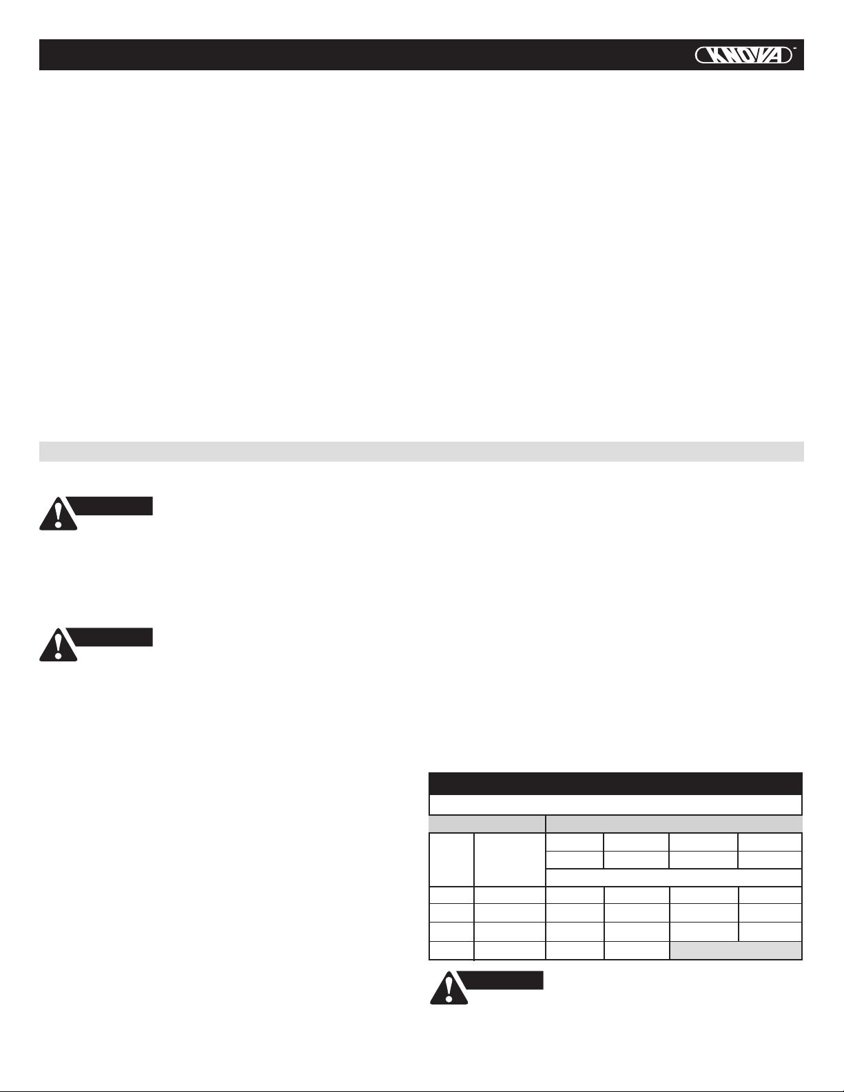
10. USE PROPER EXTENSION CORDS. Make sure your
extension cord is in good condition. When using an
extension cord, be sure to use one heavy enough to carry
the current your product will draw. An undersized cord
will result in a drop in line voltage and in loss of power
which will cause the tool to overheat. The table on page
3 shows the correct size to use depending on cord length
and nameplate ampere rating. If in doubt, use the next
heavier gauge. The smaller the gauge number,
the heavier the cord.
11. WEAR PROPER APPAREL. Do not wear loose clothing,
gloves, neckties, rings, bracelets or other jewelry which
may get caught in moving parts. Nonslip footwear is
recommended. Wear protective hair covering to contain
long hair.
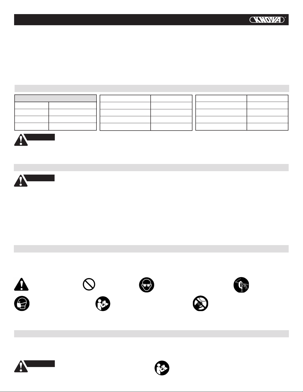
12. ALWAYS WEAR EYE PROTECTION. Any power
tool can throw foreign objects into the eyes and
could cause permanent eye damage. ALWAYS
wear Safety Goggles (not glasses) that comply
with ANSI Safety standard Z87.1. Everyday
eyeglasses have only impact–resistant lenses.
They ARE NOT safety glasses. NOTE: Glasses
or goggles not in compliance with ANSI Z87.1
could seriously injure you when they break.
13. WEAR A FACE MASK OR DUST MASK.
Sawing operation produces dust.
14. SECURE WORK. Use clamps or a vise to hold
work when practical. It is safer than using your
hand and it frees both hands to operate the tool.
15. DISCONNECT TOOLS FROM POWER SOURCE before
servicing, and when changing accessories such as blades,
bits and cutters.
16. REDUCE THE RISK OF UNINTENTIONAL STARTING.
Make sure switch is in the OFF position before plugging
the tool in.
17. USE RECOMMENDED ACCESSORIES. Consult this
Instruction Manual for recommended accessories.
The use of improper accessories may cause risk of injury
to yourself or others.
18. NEVER STAND ON THE TOOL. Serious injury could
occur if the tool is tipped or if the cutting tool is
unintentionally contacted.
19. CHECK FOR DAMAGED PARTS. Before further use of
the tool, a guard or other part that is damaged should be
carefully checked to determine that it will operate
properly and perform its intended function – check for
alignment of moving parts, binding of moving parts,
breakage of parts, mounting and any other conditions
that may affect its operation. A guard or other part that
is damaged should be properly repaired or replaced.
20. NEVER LEAVE THE TOOL RUNNING UNATTENDED.
TURN THE POWER “OFF”. Do not walk away from a
running tool until the blade comes to a complete stop
and the tool is unplugged from the power source.
21. DO NOT OVERREACH. Keep proper footing and balance
at all times.
22. MAINTAIN TOOLS WITH CARE. Keep tools sharp and
clean for best and safest performance. Follow
instructions for lubricating and changing accessories.
23. DO NOT use power tool in presence of ammable liquids
or gases.
24. DO NOT operate the tool if you are under the inuence
of any drugs, alcohol or medicationn that could affect
your ability to use the tool properly.
25. Dust generated from certain materials can be hazardous
to your health. Always operate saw in well-ventilated
area and provide for proper dust removal.
WARNING
26. People with electronic devices, such
as pacemakers, should consult their physician(s) before
using this product. Operation of electrical equipment in close
proximity to a heart pacemaker could cause interference or
failure of the pacemaker.
27. SECURE WEAR HEARING PROTECTION
to reduce the risk of induced hearing loss.
ADDITIONAL SAFETY RULES FOR SCROLL SAWS
1. READ AND UNDERSTAND all safety instructions and
operating procedures throughout the manual. Retain this
manual as it contains important information regarding
safe operation of this tool.
2. DO NOT OPERATE the Scroll Saw until it is completely
assembled and installed according to the instructions.
3. SHOULD any part of Scroll Saw be missing, damaged, or
fail in any way, or any electrical component fail to perform
properly, shut off the switch and remove the plug from
the power supply outlet. Replace missing, damaged, or
failed parts before resuming operation.
4. IF YOU ARE NOT thoroughly familiar with the operation
of a Scroll Saw, obtain advice from your supervisor,
instructor or other qualied person.
5. SERIOUS INJURY could occur if the tool tips over or you
accidentally hit the cutting tool. Do not store anything
above or near the tool.
6. AVOID INJURY from unexpected saw movement. Place
the saw on a rm level surface where the saw does not
rock and bolt or clamp the saw to its support.
7. YOUR SCROLL SAW MUST BE SECURELY FASTENED
to a stand or workbench. If there is any tendency for the
stand or workbench to move during operation, the stand
or workbench MUST be fastened to the oor.

3
ADDITIONAL SAFETY RULES FOR SCROLL SAWS
8. THIS SCROLL SAW is intended for indoor use only.
9. TENSION BLADE PROPERLY before starting the saw.
Recheck and adjust tension as needed.
10. BLADE TEETH MUST POINT downward toward the table.
11. TABLE MUST BE CLEARED of all debris before
operating saw. Do not perform lay out, set up or
assemble work on the table when the saw is in operation.
12. TO PREVENT INJURIES, avoid awkward hand or nger
positions, where a sudden slip could cause a hand to
move into the blade when operating the saw.
13. HOLD WORKPIECE FIRMLY against the table top.
14. NEVER CUT MATERIAL that is too small to be held safely.
15. DO NOT USE dull or bent blades.
16. TURN THE SAW OFF AND UNPLUG THE CORD if the
blade binds in the saw kerf while being backed out of the
workpiece, usually caused by sawdust clogging the kerf.
If this happens, turn off the scroll saw and unplug
the power cord. Wedge open the kerf and back the blade
out of the workpiece.
17. DO NOT feed the material too fast while cutting. Only
feed the workpiece at the rate the saw will cut.
18. TURN THE POWER OFF, make sure the scroll saw comes
to a complete stop before installing or removing an
accessory, and before leaving the work area.
19. DO NOT START the saw with workpiece pressing against
the blade. Slowly feed the workpiece into the moving blade.
20. WHEN CUTTING a large workpiece, MAKE SURE
the material is supported at table height.
21. EXERCISE CAUTION when cutting workpieces that are
round or irregularly shaped, workpieces can pinch
the blade.
22. ALWAYS release blade tension before loosening
the blade holder screw.
23. MAKE CERTAIN table tilting lock is tightened before
starting the machine.
24. NEVER REACH under the scroll saw table when motor
is running.
25. CHECK FOR DAMAGED PARTS before each use. Check
for alignment of moving parts, binding of moving parts,
breakage of parts, mounting or any other conditions that
may affect operation. Parts that are damaged should be
properly repaired or replaced before using the tool.
26. THINK SAFETY.
ELECTRICAL REQUIREMENTS AND SAFETY
POWER SUPPLY AND MOTOR SPECIFICATIONS
GROUNDING INSTRUCTIONS
WARNING
WARNING
To avoid electrical hazards, re hazards, or
damage to the tool, use proper circuit protection. Use a
separate electrical circuit for your tool. Your tool is wired at
the factory for 120 V operation. Connect to a 120 V, 1.6 Amp
circuit and use a 1.6 Amp time delay fuse or circuit breaker.
To avoid shock or re, if power cord is worn, cut, or damaged
in any way, have it replaced immediately.
IN THE EVENT OF A MALFUNCTION OR BREAKDOWN,
grounding provides a path of least resistance for electric currents
and reduces the risk of electric shock. This tool is equipped with
an electrical cord that has an equipment-grounding conductor
and a grounding plug. The plug must be plugged into a matching
receptacle that is properly installed and grounded in accordance
with all local codes and ordinances.
DO NOT MODIFY THE PLUG PROVIDED. If it will not t the
receptacle, have the proper receptacle installed by a qualied
electrician.
IMPROPER CONNECTION of the equipment grounding
conductor can result in risk of electric shock. The conductor with
the green insulation (with or without yellow stripes) is the
equipment grounding conductor. If repair or replacement of the
electrical cord or plug is necessary, do not connect the
equipment grounding conductor to a live terminal.
CHECK with a qualied electrician or service person if you do
not completely understand the grounding instructions, or if you
are not certain the tool is properly grounded.
USE only 3-wire extension cords that have three-pronged
grounding plugs with three-pole receptacles that accept the
tool’s plug. Repair or replace damaged or worn cords
immediately.
This tool must be grounded while in use to
protect the operator from electrical shock.
Use a separate electrical circuit for your tool. This circuit must
not be less than #18 wire and should be protected with a 1.6
Amp time lag fuse. Before connecting the motor to the power
line, make sure the switch is in the off position and the electric
current is rated the same as the current stamped on the motor
nameplate. Running at a lower voltage will damage the motor.
GUIDELINES FOR EXTENSION CORDS
USE THE PROPER EXTENSION CORD. Make sure your
extension cord is in good condition. Use an extension cord heavy
enough to carry the current your product will draw. An
undersized cord will cause a drop in line voltage resulting in loss
of power, overheating and burning out of the motor. The table
below shows the correct size to use depending on cord length
and nameplate ampere rating. If in doubt, use the next heavier
gauge. The smaller the gauge number, the heavier the cord.
Make sure your extension cord is properly wired and in good
condition. Always replace a damaged extension cord or have it
repaired by a qualied technician before using it. Protect your
extension cords from sharp objects, excessive heat and damp or
wet areas.
WARNING
This tool is for indoor use only. Do not
expose to rain or use in damp locations.
MINIMUM GAUGE FOR EXTENSION CORDS (AWG)
(When using 120 volts only)
Ampere Rating Total length of Cord
AWG - American wire gauge
More
than
25 ft
(7.62 m)
06 18 16 16 14
610 18 16 14 12
10 12 16 16 14 12
Not Recommended
12 16 14 12
(15.24 m) (30.48 m) (45.72 m)
50 ft 100 ft 150 ft
Not more
than

4
ELECTRICAL REQUIREMENTS AND SAFETY
This tool is intended for use on a circuit that has a receptacle
like the one illustrated in Fig. 1. Fig. 1 shows a three-pronged
electrical plug and receptacle that has a grounding conductor.
If a properly grounded receptacle is not available, an adapter
(Fig. 2) can be used to temporarily connect this plug to a
two-contact grounded receptacle. The adapter (Fig. 2) has a
rigid lug extending from it that MUST be connected to a
permanent earth ground, such as a properly grounded
receptacle box.
In all cases, make certain the receptacle
is properly grounded. If you are not sure, have a
qualied electrician check the receptacle.
CAUTION
Fig. 1
Fig. 2
Three-Pronged Plug
Grounding Prong
Adapter
Properly Grounded
Three-Pronged Receptacle
Make sure this
is connected to
a known ground.
Two-Pronged
Receptacle
Grounding
Lug
GLOSSARY OF TERMS
SCROLL SAW TERMS
BEVEL SCALE – Represents the degree of table angle from
0° to 45° when the table is tilted for bevel cutting.
BLADE GUARD FOOT – Guards the blade and keeps your
workpiece from rising. Helps protect ngers from blade contact.
BLADE GUARD FOOT LOCK KNOB – Allows you to raise or
lower the foot and lock it at the desired height.
BLADE HOLDERS – Retain and position the blades.
BLADE STORAGE – Provides convenient easy access to
extra blades or wrenches.
QUICK RELEASE TENSION LEVER – Quickly loosens and
retightens the blade to its original tension. The tension lever
quickly sets and resets the blade tension when performing
interior cutting operations or changing blades.
SAWDUST BLOWER – Keeps sawdust from covering the line
of sight for more accurate cuts. The best results occur when
the blower tube is directed toward the blade and workpiece.
SAWDUST COLLECTION PORT – Allows vacuum hose or
attachments to be used to remove the sawdust from under
the table and base.
TABLE LOCK KNOB – Securely locks the table at the angle
desired for bevel cutting.
VARIABLE SPEED CONTROL KNOB – Variable switch dial
allows greater versatility when cutting a variety of materials.
Adjust the speed to the desired setting, between 500 to 1500
strokes per minute (SPM), by turning the control knob
clockwise or counterclockwise.
WOODWORKING TERMS
BLADE TOOTH SET – The total width the blade will cut based
on the distance from the outside point of one bent tooth to the
outside point of the next bent tooth establishing set of teeth.
DEFLECTION – Slight movement of blade in the horizontal
direction while the blade is moving inline during cutting opera-
tion. This may be caused by the blade following the grain or
the path of least resistance.
FEED – Rate of moving material to be cut into the blade.
KERF – The slot cut by the blade.
LEADING EDGE – The front edge of the workpiece that is
guided into the blade.
SAW BLADE PATH – Area or line of sight of the workpiece
moving in line toward the saw blade edge.
SURFACE – Top of workpiece being cut.
TRAILING EDGE – The end of the workpiece edge last cut by
the saw blade.
WORKPIECE – Material on which the cutting operation is
being performed.
Saw blade path
Trailing edge
Leading edge
Kerf
Surface
Workpiece

5
TOOLS NEEDED FOR ASSEMBLY
SUPPLIED NOT SUPPLIED
3 mm hex key Slotted screwdriver
#2 Phillips screwdriver
Adjustable wrench
13 mm wrench
CARTON CONTENTS
A. Scroll saw
assembly B. Blade bag
- 5 in. pin-end blade
- 3 mm hex key
C. Side bracket
- Upper supports
D. Side bracket
- lower supports
E. Rear bracket
- upper & lower
supports G. Stand hardware bag
F. Front bracket
- upper & lower
supports
H. Stand leg
(front)
I. Stand leg
(rear)
1. Carefully unpack the scroll saw
and all its parts, and compare
against the list below and
the illustration.
2. With the help of an assistant,
place the saw on a secure
surface and examine it carefully.
• To avoid injury from unexpected starting or electrical shock,
do not plug the power cord into a source of power during unpacking and
assembly. The cord must remain unplugged whenever you are adjusting/ assembling
the scroll saw.
• The scroll saw is heavy and should be lifted with care. If needed, get the
assistance of someone to lift and move the scroll saw.
• If any part is missing or damaged, do not attempt to assemble the scroll saw,
or plug in the power cord until the missing or damaged part is correctly replaced.
WARNING

KNOW YOUR SCROLL SAW
6
Expanded
view
Stand
Foot pad
5 in.
plain-end blade
Variable speed
control knob
Blade
holder
lock knob
Blade guard foot
lock knob
Blade tension
lever
LED work
light
Blade
holder
REAR
FRONT
LED work light
ON/OFF switch
Mounting
hole
Sawdust
blower
Blade storage
(under table)
Table lock
knob
Table top
bevle scale Motor
Worktable
Table
insert
Blade
guard foot
ON/OFF
switch

7
ASSEMBLY AND ADJUSTMENTS
Estimated Assembly Time: 25-40 Minutes.
INSTALLING THE STAND (FIG. A)
1. Unpack all parts and group by type and size. Refer to the
table of loose parts list on page 5 for correct quantities.
2. Bag “F” & “H” - Attach one leg of front bracket - upper
support (1) to top of leg, marked “F” (2) using one
bolt (3) and nut (4). The stand leg is placed on
the outside of the brackets.
NOTE:
• The left side of the bracket has only one hole and
the right side has two holes.
• Only hand tighten at this point. Do not tighten bolts
with a wrench until stand is properly aligned
(see step #8 before tightening).
• The front and rear stand legs are different in angles
and cannot be mixed. The two front stand legs are
marked with a “F” and the two rear stand legs are
marked with a “R”.
3. Attach other end of front bracket - upper support (1) to
top of another leg (2) using two bolts (3) and nuts (4).
4. Attach the front bracket - lower support (5) to center
the two legs using bolt (3) and nut (4). This completes
the front frame section.
5. Bag “E” & “H” - Assemble rear frame section in exactly
the same manner using the shorter rear brackets (13 & 14).
6. Bag “C” & “D” - Join the front and rear frame sections
using two brackets upper supports (6) and two lower
supports (7) with bolts and nuts.
7. Bag “G” - Place the four foot pads (8) into the bottom
of each leg, lightly use a rubber mallet if needed.
NOTE: The foot pads for the front stand legs and the rear
stand legs are different and cannot be mixed. The two
larger foot pads are marked (F) and must be placed on
the front stand legs. The two smaller foot pads are
marked (R) and must be placed on the rear stand legs.
8. Place the stand on level surface, adjust all legs to contact
and are at similar angles to the oor. Tighten all bolts.
NOTE: To avoid rocking, all bolts must be tightened
securely using a 13 mm or adjustable wrench.
WARNING
• The stand is designed only for use with
a scroll saw.
• Do not climb, sit or stand on the stand assembly.
• Do not use the stand on uneven or unstable surface.
• To avoid injury, do not connect this scroll saw
to the power source until it is completely assembled
and adjusted and you have read and understood this
instruction manual.
9
4
1
3
2 (F)
8 (F)
7
8 (R)
6
5
10
12 11
13
14
2 (R)
Front side of
frame assembly
MOUNTING THE SCROLL SAW (FIG. B)
1. To mount your scroll saw to the stand, position
the assembled stand on a rm, level surface.
2. Line up the four holes (15) on the scroll saw base with
the holes in the stand leg, place the scroll saw on
the stand.
3. Secure the saw to the two mounting holes in the front of
the stand using the two hex bolts (9), two at washers
(10), two sleeves (11) and two nuts (12) provided.
4. Secure the saw to the two mounting holes in the rear of
the stand using the two hex bolts (9), two at washers
(10) and two nuts (12) provided.
NOTE: No sleeves (11) are used for these two mounting
holes.
5. Tighten all four nuts using two 13 mm or adjustable
wrenches.
NOTE: Do not over tighten nuts, it may damage the saw
base.
12
15
10
9
11
10
915
12
Fig. A
Fig. B
Front

8
ASSEMBLY AND ADJUSTMENTS
MOUNTING SCROLL SAW TO WORK SURFACE (FIG. C)
1. If mounting the scroll saw to a workbench instead of
the provided stand, a solid wood bench is preferred over
a plywood board to reduce noise and vibration.
2. The hardware to mount this saw is NOT supplied with
the saw. The hardware as shown in Fig. C should be used.
BLADE STORAGE (FIG. D)
Blade storage is located on the right side of the scroll saw
body. Pull out the blade storage drawer (1) to open.
The compartment can conveniently store your hex key and
both pin-end and plain-end blades.
SAWDUST COLLECTION PORT (FIG. E)
This scroll saw will accept a 1-1/4 in. diameter hose or
vacuum accessory (not provided) to be connected to
the port (1) on the right side of base.
PLAIN-END BLADE REMOVAL AND
INSTALLATION (FIG. F, G, H, I)
This scroll saw accepts 5 in. (127 mm) length plain-end or
pin-end blades to cut a wide variety of materials.
BLADE REMOVAL AND INSTALLATION
1
2
3
2
4
1
6
5
1. Hex bolts; length
as required
2. Flat washers
3. Foam pad or
carpet (optional)
4. Lock washers
5. Hex nuts
6. Jam nuts
Fig. D
1
Fig. E
Plain-end type blades are recommended whenever ne,
accurate and intricate work is being performed on 3/4 in.
(19 mm) or thinner material. It will take slightly longer to
install the blade and adjust blade tension, but you will also be
able to use ner blades for cutting a thinner kerf.
Plain-end blade removal (Fig. F, G, H)
1. Remove the table insert (1) by pushing it up from under
the worktable. (Fig. F)
NOTE: Be careful not to make contact with the blade.
2. To remove the blade, loosen the blade tension by lifting
the blade tension lever (2). If needed, turn the blade
tension lever counterclockwise to reduce the tension
further.
3. Loosen the upper blade holder (3) by turning the blade
holder lock knob (4) counterclockwise. (Fig. F, G)
NOTE: The hex set screw (5) on the right side is used for
ne adjustments and is only adjusted if the blade is not
perpendicular to the table.
4. Tilt the worktable to 45° left and tighten the table lock
knob (8-Fig. H). Loosen the lower blade holder lock
knob (6) on the right side of the lower blade holder (7)
under the table by turning it counterclockwise. (Fig. G)
5. Push down the upper arm (10-Fig. G), and remove
the blade (9) from the upper and lower blade holders by
pulling forward. (Fig. H)
WARNING
To avoid injury from accidental starting,
always turn the switch OFF (O) and remove power
cord plug from power source before removing or replacing
the blade.
2
4
3
1
5
Fig. F
Blade tension lever
Tighten
Release
10
2
5
3
4
7
6
Fig. G
Fig. C

9
ASSEMBLY AND ADJUSTMENTS
9
8
Fig. H
Plain-end blade installation (Fig. H, I)
In order to avoid uncontrollable lifting of
the workpiece, the teeth of the blade should
ALWAYS point downward.
CAUTION
NOTE: The worktable should still be at 45 degrees left and
the table insert is removed from the worktable.
1. Insert the new blade (9) with teeth pointing down into
the lower blade holder slot (7), then tighten the lower
blade holder lock knob (6). (Fig. I)
2. Tilt the table back to the 0° bevel setting and lock the table
lock knob (8). (Fig. H)
3. Insert the other end of the blade into the upper blade
holder slot (3), then tighten the upper blade holder lock
knob (4). (Fig. I)
NOTE:
• Apply slight downward pressure against the upper
arm (10) when installing the blade into the upper
blade holder.
• If required, clamp plain-end blades more tightly by
using a 3 mm hex key through the hex set screw (5).
4. Tighten the blade tension by pressing down the blade
tension lever (2). If tension is too tight, turn the blade
tension lever (2) counterclockwise. If tension is too loose,
turn the blade tension lever clockwise.
5. Replace the table insert, making sure it is not above
the worktable surface.
Pin-end type blades are often thicker than plain-end blades
and offer more stability and faster assembly. These blades
are used whenever faster cutting on a variety of materials and
3/4 in. (19 mm) thickness or greater are required. Use
whenever less precision or thicker kerf cutting is acceptable.
NOTE: When installing pin-end blades, the hex set screws
located on the upper and lower blade holders should not be
over or under tightened. The slot must be slightly wider than
the thickness of the blade. After the blade is installed,
the blade tension mechanism will keep the pin-end in place.
Pin-end blade removal (Fig. F, H, J, K)
1. Remove the table insert (1-Fig. F) by pushing it up from
under the worktable.
NOTE: Be careful not to make contact with the blade.
2. To remove the blade, loosen the blade tension by lifting
the blade tension lever (2). (Fig. J)
3. Loosen the upper blade holder (3) by turning the blade
holder lock knob (4) counterclockwise. (Fig. K)
4. Tilt the table to 45° left and tighten the table lock knob
(8-Fig. H). Loosen the lower blade holder lock knob (6)
on the right side of the lower blade holder (7) under
the table by turning it counterclockwise.
5. Remove the blade (9) from the upper (3) and lower (7)
blade holder by pulling down the arm, then pulling
forward to release the blade (9).
NOTE: Apply slight downward pressure on the upper arm
when removing blade from upper blade holder.
Overtightening blade will blade breakage.
CAUTION
NOTE: The blade tension
lever must always be
down to make tension
adjustments. Release
the blade tension
lever only during blade
changing operations.
If the blade is tightened
too tight, the lever will
be difcult to lower and
could result in damage
to the blade holder or
arm assembly. (Fig. I)
10
4
2
5
3
9
6
7
PIN-END BLADE REMOVAL AND INSTALLATION
(FIG. F, H, J, K, L)
WARNING
To prevent personal injury, always turn
the saw OFF and disconnect the plug from the power
outlet before changing blades or making adjustments.
2
Fig. J
Blade tension lever
Tighten
Release
2
3
9
6
7
4
Fig. K
Fig. I

ASSEMBLY AND ADJUSTMENTS
10
Pin-end blade installation (Fig. H, L)
NOTE: Do not tighten the blade holder lock knobs when using
pin-end blades.
WARNING
In order to avoid uncontrollable lifting of
the workpiece, the teeth of blade should always
point downward.
1. To install a new 5 in. pin-end blade, rst insert the blade
into the lower blade holder (7), making sure the pins are
properly located in the slots (see Fig. L-2). Then place
the blade into the slot in upper blade holder (4). (Fig. L)
2. Tighten the upper (4) and lower (6) blade holder lock knob.
3. To tension the blade (9), lower the blade tension lever (2).
Check the tension on the blade. If tension is too tight,
turn the blade tension lever (2) counterclockwise.
If tension is too loose, turn the blade tension lever
clockwise.
NOTE: If the blade is over tightened, the lever will be
difcult to lower and could result in damage to the blade
holder or arm assembly.
4. Tilt the table back to the 0° bevel setting and lock the table
lock knob (8). (Fig. H)
5. Replace the table insert, making sure it is not above
the worktable surface.
BLADE GUARD FOOT ADJUSTMENT (FIG. M)
NOTE: User must keep constant downward pressure on
workpiece when cutting. The blade guard foot is not designed
to hold down the workpiece, but is rather to help prevent the
workpiece from lifting up excessively.
When cutting at angles, the blade guard foot (1) should be
adjusted so it is parallel to the table and rests at above the
workpiece.
1. To adjust, loosen the blade guard screw (2) with the 3 mm
hex key, adjust the blade guard foot (1) parallel to table,
and tighten the screw (2).
2. Loosen the blade
guard foot lock
knob (3) to raise
or lower the foot
until it rests
slightly above
the workpiece.
Tighten blade
guard foot
lock knob (3).
2
3
9
6
3
2
1
7
4
Fig. L
Pins
Fig. L-2
Fig. M
SAWDUST BLOWER (FIG. N)
The sawdust blower (1) should be
positioned to point to the blade and
workpiece to blow sawdust out of
the line-of-sight when cutting.
It is not designed to blow all
of the sawdust off the table.
This scroll saw accepts 5 in. (127 mm) length blades with a
wide variety of blade thickness and widths. The type of
material and cutting operations (size of radius or curve) will
determine the number of teeth per inch. As a rule, always
select the narrowest blades for intricate curve cutting and the
widest blades for straight and large curve cutting operations.
The following table represents suggestions for various
materials. When purchasing blades, refer to the back of
the package for the best use of blades and speeds on various
materials.
Use this table as an example, but practice and your own
personal preference will determine the best selection method.
BLADE SELECTION (FIG. O) 1
WARNING
To avoid injury from
accidental starting, always
turn the switch OFF and
unplugthe scroll saw before moving,
replacing the blade or making adjustments.
Fig. O
9.5 - 15 15 - 28 30 - 48
TEETH / INCH
TPI BLADE
WIDTH INCH BLADE/ SPM
BLADE
THICKNESS INCH
MATERIAL CUT
Medium turns on
1/4 in. (6.35 mm) to
1-3/4 in. (44.45 mm) wood,
soft metal, hardwood
Small turns on
1/8 in. (3.18 mm) to
1-1/2 in. (38.1 mm) wood,
soft metal, hardwood
Non-ferrous
metals/hardwoods
using very slow speeds
400-1200
9.5-15
15-28
30-48
0.018
(0.46 mm)
0.110
(2.8 mm)
.055-.110
(1.4-2.8 mm)
024-.041
(0.6-1.0 mm)
.010-.018
(0.25-0.46 mm)
.012-.019
(0.3-0.48 mm)
800-1800
Varies
NOTE: When using blades, sometimes speeds must change
to compensate for smaller curves, radii or smaller diameters.
Thinner blades will have more possibilities for blade deection
when cutting angles which are not perpendicular to the table.
Read RECOMMENDATION FOR CUTTING for more
suggestions.
NOTE: The blade must be installed with the teeth pointing
downward, to prevent the workpiece from being pulled
upward by the saw blade action.
Fig. N

OPERATING THE TOOL
11
VARIABLE SPEED CONTROL AND ON/OFF SWITCH
For your own safety, always push
the switch “OFF” when the scroll saw is not in use.
Also, in the case of power failure (all of your lights go out)
push the knob “OFF”. Remove the plug from the power
source outlet to avoid accidental starting.
CAUTION
ON/OFF SWITCH (FIG. P)
1. To turn power ON, press on/off switch (1) to “ON”
position.
2. To turn power OFF, press on/off switch (1)
to “OFF” position.
VARIABLE SPEED CONTROL KNOB (FIG. P)
The variable speed control allows greater versatility to cut a
variety of materials such as wood, plastics, non-ferrous
metals, etc. Depending on the hardness and thickness of
material, the speed should be reduced to allow the blade
teeth to remove cut material from the kerf.
1. Your saw is equipped with a variable speed control
knob (2). The blade stroke rate may be adjusted by
simply rotating the variable speed control knob (2).
2. Turn the speed control knob clockwise to increase
up to 1,500 strokes per minute (SPM). Turn the speed
control knob counterclockwise to reduce down to
500 strokes per minute (SPM).
WORK LIGHT (FIG. P)
1. To turn work light on,
press the rocker
switch (3)
to “ON” position.
2. To turn work light
off, press the rocker
switch (3) to “OFF”
position.
1
23
RECOMMENDATIONS FOR CUTTING
1. When feeding the workpiece into the blade do not force
the leading edge of the workpiece into the blade because
the it will deect the blade, reduce the accuracy of
cutting and possibly break the blade. Allow the saw to
cut material by guiding the workpiece into the blade
as it cuts.
2. The blade teeth cut material ONLY on the down stroke.
3. You must guide the wood into the blade slowly because
the teeth of the blade are very small and they can only
remove wood when they are on the down stroke.
4. There is a learning curve for each person who wants to
use this saw. During that period of time it is expected
that some blades will break until you learn how to use
the saw and receive the greatest benet from the blades.
5. Best results are achieved when cutting wood less than
one inch (25.4 mm) thick.
6. When cutting wood thicker than one inch (25.4 mm),
the user must guide the wood very slowly into the blade
and take extra care not to bend or twist the blade while
cutting in order to maximize blade life.
7. When teeth of scroll saw blade worn out, must replace
the new blade. Check the blade frequently for best
cutting results. Scroll saw blades generally stay sharp
for 1/2 to 2 hours of cutting.
8. To get accurate cuts, be prepared to compensate for
the blade’s tendency to follow the wood grain as you
are cutting.
9. This scroll saw is intended to cut wood or wood products.
10. When choosing a blade to use with your scroll saw,
consider very ne, narrow blades to scroll cut in thin
wood in 1/4 in. (6.4 mm) thick or less. Use wider blades
for thicker materials but this will reduce the ability
to cut tight curves.
11. This saw uses 5 in. (127 mm) long pin or plain end
type blades.
12. Blades wear faster when cutting plywood or particle
board which is very abrasive. Angle cutting in hardwoods
reduces blade tooth set faster due to the blade deection.
FREEHAND CUTTING (FIG. Q)
1. Lay out desired design, or secure design to
the workpiece (1).
2. Raise the blade guard foot (2) by loosening the blade
guard foot lock knob (3).
3. Position the workpiece against the blade and place
the blade guard foot slightly above the top surface
of the workpiece.
4. Secure the blade guard foot (2) by tightening the blade
guard foot lock knob (3).
5. Remove the workpiece from the blade before turning
the scroll saw ON. Set the desired speed by turning the
speed control knob (4) clockwise or counterclockwise.
In order to avoid uncontrollable lifting of
the workpiece and to reduce blade breakage, do not
turn saw ON while the workpiece is against the blade.
CAUTION
6. When turning the scroll saw ON, position the workpiece
against scrap wood prior to touching the leading edge
of the workpiece against the blade.
NOTE: For your own safety, use the scrap wood to
perform the cutting especially for the small workpiece.
7. Slowly feed the workpiece into the blade by guiding and
pressing the workpiece down against the table.
8. When the cut is
complete, move
the trailing pieces
of the workpiece
beyond the blade
guard foot. Turn
the scroll saw OFF.
Do not force the leading edge of
the workpiece into the blade, it may deect
the blade, reduce accuracy of cutting, and possibly break
the blade.
CAUTION
4
1
2
9
3
Fig. Q
Fig. P

OPERATING THE TOOL
12
ANGLE CUTTING (FIG. Q, R, S) RIP OR STRAIGHT LINE CUTTING (FIG. T)
Tools Needed (Not Included)
QUANTITY DESCRIPTION
Small C-clamps
Ruler or measuring tape
12-inch (304.8 mm) -straight scrap of wood
(Thickness to match workpiece)
A piece of wood, metal, plastic
etc. with a straight edge
WARNING
To avoid injury, always keep your hands
off the underneath of the table during operating.
Left Bevel Cutting (maximum 45 degrees) (Fig. Q, R)
1. Lay out or secure design to workpiece (1). (Fig. Q)
2. Move the blade guard foot (2) to the highest position by
loosening the blade guard foot lock knob (3) and retighten.
3. Tilt the table (5) to the desired angle by loosening
the table lock knob (6) and move the table to the proper
angle, using the degree scale (7) and the pointer (8).
(Fig. R)
4. Tighten the table lock knob (6).
5. Loosen the blade guard screws (9-Fig.Q), and tilt
the blade guard to the same angle as the table (5).
Retighten the blade guard screw.
6. Position the workpiece on the left and right side of
the blade (10). Lower the blade guard foot slightly
above the surface of the workpiece by loosening
the blade guard foot lock knob (3).
7. Follow steps 4-8 under FREEHAND CUTTING
OPERATION.
1. Raise the blade guard foot (1) by loosening the blade
guard foot lock knob (2) on the left side of the upper arm.
Measure from the tip of the blade (3) to the desired
distance. Position the straight edge (4) parallel to
the blade at that distance.
2. Clamp the straight edge (4) to the table (5).
3. Recheck your measurements, using the workpiece to be
cut, and make sure the scrap wood (6) is secure.
4. Position the workpiece against the blade and place
the blade guard foot (1) slightly above the top surface
of the workpiece.
5. Secure the blade guard foot in place by tightening
the blade guard foot lock knob.
6. Remove the workpiece from the blade before turning
the scroll saw ON. Set the desired speed by turning
the speed control knob clockwise or counterclockwise.
7. Position the workpiece against the straight edge (4)
prior to touching the leading edge of the workpiece
against the blade (3).
8. Slowly feed the workpiece into the blade, guiding
the workpiece against the straight edge and press
the workpiece down against the table while cutting.
9. When the cut is complete, move the trailing edge
of the workpiece beyond the blade guard foot.
Turn the scroll saw OFF.
NOTE: Use push stick when cutting a narrow workpiece.
3
10
2
1
6
5
87
Fig. R
Right Bevel Cutting (maximum 15 degrees) (Fig. R, S)
1. Lay out or secure design to workpiece (1). (Fig. R)
2. Move the blade guard foot (2) to the highest position by
loosening the blade guard foot lock knob (3) and retighten.
3. Tilt the table (5) to the left by loosening the table lock
knob (6), and lifting the anchor plate (11-Fig. S) to
the rear of the saw. Tilt the table to the right, it will
stop at the angle of 15°.
4. Tighten the table
lock knob (6).
5. Follow steps 5-7
under Left Bevel
Cutting.
11
Fig. T
2
1
1
1
In order to avoid uncontrollable lifting
of the workpiece and reduce blade breakage,
do not turn saw ON while the workpiece is against
the blade.
CAUTION
3
1
5
4
6
2
Fig. S
Do not force the leading edge of
the workpiece into the blade. The blade will deect,
reducing accuracy of cut and may break.
CAUTION

OPERATING THE TOOL
13
INTERIOR CUTTING (FIG. U)
1. Lay out the design on the workpiece (1).
Drill a 1/4 in. (6.4 mm) hole in the workpiece.
2. Lift the blade tension lever (2) and remove the blade (3).
Refer to BLADE REMOVAL AND INSTALLATION.
3. Place the workpiece on the table with the workpiece
hole (4) over the access hole in the table (5).
4. Install the blade (3) through the hole in the workpiece and
press the blade tension lever (2).
5. Follow the process 3-8 under the section
of FREEHAND CUTTING.
6. When nish the cutting, turn the scroll saw OFF,
remove the blade from the blade holders and remove
the workpiece from the table.
ALWAYS use safety glasses. Everyday eyeglasses are
NOT safety glasses. Also use face or dust mask if cutting
operation is dusty. ALWAYS WEAR CERTIFIED SAFETY
EQUIPMENT:
• ANSI Z87.1 eye protection (CAN/CSA Z94.3),
• ANSI S12.6 (S3.19) hearing protection,
• NIOSH/OSHA/MSHA respiratory protection.
An occasional coat of paste wax on the work table will allow
the wood being cut to glide smoothly across the work surface.
Ball bearings in the scroll saw are packed with grease at
the factory and require no further lubrication.
Use only mild soap and a damp cloth to clean the tool.
Never let any liquid get inside the tool; never immerse any
part of the tool into a liquid.
GENERAL MAINTENANCE
Fig. U
3
4
2
5
1
MAINTENANCE
WARNING
WARNING
For your own safety, turn the switch off
and remove the plug from the power source outlet
before maintaining or lubricating your scroll saw.
Frequently blow out dust and
grit that accumulates in the motor housing
using compressed air.
WARNING
To avoid shock or re hazard,
if the power lead is worn or cut in any way,
replace it immediately.
LUBRICATION
IMPORTANT: To assure product SAFETY and RELIABILITY,
repairs, maintenance and adjustment (other than those
listed in this manual) should be performed by authorized
service centers or other qualied service organizations,
always using identical replacement parts.
FREE WARNING LABEL REPLACEMENT: If your warning
labels become illegible or are missing,
call 01-800- 70-KNOVA (56682) for a free replacement.

TROUBLESHOOTING GUIDE
WARNING
To avoid injury from an accidental start,
turn the switch OFF and always remove the plug
from the power source before making any adjustments.
PLEASE READ THE FOLLOWING: The manufacturer
and/or distributor is providing the buyer with a parts list and
assembly diagram in this manual as a reference tool only.
Neither the manufacturer nor distributor make any
representation or warranty of any kind to the buyer regarding
the accuracy of the list or diagram or that buyer is qualied
and able to make any repairs or replace any parts of
the product. The manufacturer and/or distributor expressly
recommend: that all repairs and/or part replacements only
be undertaken by a certied and licensed technician, and not
by the buyer. The buyer assumes all risk and liability, including
injuries to persons and damage to property, associated with
and arising out of any attempt of the buyer at repairs or
replacement of parts to the product.
SYMPTOM
Breaking blades
Blade run out.
Blade not in line
with arm motion.
Motor will
not run.
Excessive
vibration.
NOTE: There will
always be some
vibration present
when the saw is
running because
of motor
operation.
1. Wrong tension.
2. Overworking blades.
3. Wrong blade application.
4. Twisting blade in wood.
1. Blade holders not aligned.
1. Defective cord or plug.
2. Defective motor.
3. Blown overload breaker.
1. Improper mounting of saw.
2. Unsuitable mounting surface.
3. Loose table or table
resting against motor.
4. Loose motor mounting.
1. Adjust blade tension. See BLADE REMOVAL
AND INSTALLATION section.
2. Reduce feed rate. See BLADE REMOVAL
AND INSTALLATION section.
3. Use narrow blade. See BLADE SELECTION section.
4. Avoid side pressure on blade. See BLADE
REMOVAL AND INSTALLATION section.
1. Loosen blade holder lock screw holding blade holder to
arms. Adjust position of blade holders. Retighten blade
holder lock screw.
See BLADE REMOVAL AND INSTALLATION section.
1. Replace defective parts before using saw again. See
ELECTRICAL REQUIREMENTS AND SAFETY section.
2. Call Service Center. Any attempt to repair this motor
may create a HAZARD unless the repair is done by
a qualied technician.
3. Push the on/off switch to the OFF (O) position.
Let the motor cool. See OPERATION OVERLOAD
BREAKER section.
1. See mounting instructions in this manual for
proper mounting technique.
2. The heavier your workbench is, the less vibration will
occur. A plywood workbench will not be as good a work
surface as the same size solid lumber.
3. Tighten the table lock knob.
4. Tighten motor mounting screw.
POSSIBLE CAUSES CORRECTIVE ACTION
14

Description Qty.
I.D. No.
PARTS LIST
Size
0A98 COMPRESSION SPRING 1
0AM3 WASHER 1
0C10 PLAIN-END BLADE 1
0DEJ RUBBER PAD 3
0DF6 BELLOW 1
0DF8 PLUG HOUSING 1
0ES8 PVC HOSE 1
0HFW BOLT CLAMP 1
0J4E FLAT WASHER Ø 6 x 13-1 2
0J4U FLAT WASHER
Ø 6 x 18-1.5
3
0J66 FLAT WASHER Ø 4 x 10⁻¹ 2
0JAF EXTERNAL TOOTH LOCK WASHER Ø 5 1
0JAZ WAVE WASHER 2
0JB0 WAVE WASHER 1
0JC8 SPRING PIN 2
0JCH SPRING PIN 2
0JDA SPRING PIN 1
0JMM O-RING 2
0JPG HEX. HD. BOLT M6 x 1.0-30 1
0JUD HEX. SOC. HD. CAP BOLT M5 x 0.8-20 3
0JUL HEX. SOC. HD. CAP BOLT M6 x 1.0-20 1
0JUP HEX. SOC. HD. CAP BOLT M6 x 1.0-35 1
0JXR HEX. SOC. SET SCREW M8 x 1.25-8 1
0JZB HEX. SOC. SET SCREW M4 x 0.7-6 1
0K0T HEX. HD. SCREW AND WASHER
M8 x 1.25-20
7
0K23 HEX SOC. HD. CAP SCREW M6 x 1.0-16 3
0K25 HEX. SOCKET HD. CAP SCREW M5 x 0.8-20 2
0K56 CR. RE. COUNT HD. SCREW M5 x 0.8-12 4
0K6X CR. RE. TRUSS HD. SCREW M4 x 0.7-6 1
0K71 CR. RE. TRUSS HD. SCREW M5 x 0.8-8 2
0K72 CR. RE. TRUSS HD. SCREW M5 x 0.8-12 2
0K7F
CR. RE. ROUND WASHER HD. SCREW
M5 x 0.8-8 4
0K7X
CR. RE. TRUSS HD. ROUND NECK SCREW
M6 x 1.0-10 1
0KA5 CR. RE. PAN HD. TAPPING SCREW M4 x 16-20 1
0KBA CR. RE. PAN HD. TAPPING SCREW M5 x 16-12 2
0KDJ CR. RE. PAN HD. SCREW M5 x 0.8-12 3
0KDK CR. RE. PAN HD. SCREW M5 x 0.8-16 1
0KDV CR. RE. PAN HD. SCREW M6 x 1.0-16 10
0KFE CR. RE. PAN HD. SCREW M5 x 0.8-6 1
0KMS HEX. NUT
M6 x 1.0 T=5
1
0KQW LOCK NUT
M5 x 0.8 T=5
1
0KQX NUT
M6 x 1.0 T=6
2
0LN4 WIRE CONNECTOR 1
22A4 LOCKING CABLE TIE 3
22XF CR. RE. PAN HD. TAPPING SCREW M3 x 20-15 1
23CT CR. RE. PAN HD. TAPPING SCREW M5 x 12-15 2
24ZT HEX. SOCKET HD. CAP SCREW M4 x 0.7-12 1
25B1 CR. RE. TRUSS HD. SCREW M5 x 0.8-25 1
25ZQ SPACER 1
25ZR BRACKET STOP 1
263T CROWN NUT
M6 x 0.75 T=5
1
263W SQUARE NUT
M6 x 0.75 T=5
1
27XG ROLL PIN 1
2A4U TURNTABLE 1
2E63 ROCKER SWITCH 1
2EBB
CR. RE. COUNT HD. TAPPING SCREW
M5 x 12-16 2
2EBZ TURNTABLE COVER 1
2EC3 PLATE COVER 1
2EC4 GUIDE HOLDER 1
2EC5 COVER 1
2ECB WIRE ROPE ASS’Y 1
2EZ1 CR. RE. TRUSS HD. SCREW
M5 x 0.8-10
2
18 IN. SCROLL SAW
PARTS LIST FOR SCROLL SAW
Description Qty.
I.D. No. Size
2FBG
CR. RE. ROUND WASHER HD. SCREW
M6 x 1.0-12
2
2GBJ CR. RE. PAN HD. SCREW
M5 x 0.8-12
3
2XRP ROCKER SWITCH 1
2XZL TENSION HANDLE 1
2XZP PLUNGER HANDLE 1
2Y6G FOLLOWER PLATE 1
36CM BASE GROUP 1
36CP BASE GROUP 1
36CV BOTTOM ARM ROCKER 1
36CW UPPER ARM ROCKER 1
36CX SWITCH BOX COVER 1
36CY SWITCH BOX GROUP 1
36CZ TABLE 1
36D1 BLADE BOX 1
36D2 RETAINING CLIP 1
36D3 BODY ASS’Y 1
36E9 MOTOR COVER 1
36EG ADJUST BOLT 1
36EJ SIDE COVER 1
36EM DUST COLLECTOR 1
36EP SWITCH BOX COVER 1
36ER PUSH BUTTON 1
36EU SCALE 1
36EW SIDE COVER 2
36F1 CLAMP HANDLE 1
36F2 SPECIAL BOLT 2
36F3 LOCKING ROD 1
36F6 GUIDE BLOCK 1
36FA SHAFT-PIVOT 1
36FE SPEED CONTROL BUTTON 1
36FH RETAINING CLIP ASS’Y 1
37US STRAIGHT LINKAGE BAR 1
37VC ECCENTRIC 1
3877 TRUNNION BRACKET 1
3C92 AIR DUCT ASS’Y 1
3C93 MOTOR ASS’Y 1
3C96 LED WORK LIGHT ASS’Y 1
3C9W CONTROLLER ASS’Y 1
3C9Y INSERT 1
3CA3 LEAD WIRE ASS’Y 1
3CA4 LEAD WIRE ASS’Y 1
3CB9 VARIABLE RESISTOR ASS’Y 1
3CCB HOLDER BLADE ASS’Y 2
3CCE BEARING SEAT ASS’Y 1
3CVE ROLL PIN 1
3CVM SUPPORT ROD 1
3CVQ ANCHOR PLATE 1
3CX0 CR. RE. PAN HD. TAPPING SCREW M3 x 24-8 1
3EPQ TILTING SCALE 1
3FAY HOSE 1
3FD3 SPRING GUARD 1
3HR0 HOUSING (RIGHT) 1
3HR1 HOUSING (LEFT) 1
47MM TRADEMARK LABEL 1
47MN MOTOR TRADEMARK LABEL 1
47MP CAUTION LABEL 1
47MT INSTRUCTION MANUAL 1
47P1 CAUTION LABEL 1
47P2 WARNING LABEL 1
47P3 WARNING LABEL 1
47P4 CAUTION LABEL 1
HARDWARE BAG
3CWM
B. BLADE ASS’Y 1
15

SCHEMATIC
B. HARDWARE BAG
16
Variable speed
scroll saw
18
”
Sierra caladora de velocidad variable
(457 mm)
KN SS-18VVS

STAND PARTS LIST
17
Description Qty.
I.D. No. Size
36FN SIDE BRACKET - UPPER SUPPORT 2
36FQ FRONT BRACKET - LOWER SUPPORT 1
36FR REAR BRACKET - LOWER SUPPORT 1
36FS SIDE BRACKET - LOWER SUPPORT 2
36FT REAR BRACKET - UPPER SUPPORT 1
36FU STAND LEG (FRONT) 2
36FV STAND LEG (REAR) 2
36JB FRONT BRACKET - UPPER SUPPORT 1
3EPT CAUTION LABEL 2
3EPU CAUTION LABEL 2
47MQ WARNING LABEL 1
18 IN. SCROLL SAW
PARTS LIST FOR STAND
Description Qty.
I.D. No. Size
3EXM G. HARDWARE BAG
0J4W FLAT WASHER
Ø 8.2 x 18-1.5
4
0JPS HEX. HD. BOLT
M8 x 1.25-45
4
0KRR
SERRATED TOOTHED HEXAGON FLANGE NUT
M8 x 1.25 T=7.5
24
0Z1G CAP HD. SQ. NECK BOLT
M8 x 1.25-12
20
2LBF SLEEVE 2
36FL FOOT PAD SMALL (FRONT) 2
36JA FOOT PAD LARGE (REAR) 2
STAND SCHEMETIC
G. HARDWARE BAG
Variable speed
scroll saw
18
”
Sierra caladora de velocidad variable
(457 mm)
KN SS-18VVS

18
NOTES

19
INDICE
Indice .............................................................................. 19
Especicaciones ............................................................. 19
Advertencia de propuesta 65 ......................................... 19
Pautas de seguridad / deniciones ................................ 19
Seguridad en el manejo de herramientas eléctricas ....... 20
Instrucciones de seguridad para esta sierra caladora .... 21
Requisitos eléctricos y de seguridad .............................. 22
Glosario de terminos ...................................................... 23
Herramientas necesarias para el montaje ...................... 23
Contenido del embalaje .................................................. 24
Familiarícese con su sierra caladora .............................. 25
Ensable y ajustes ........................................................... 26
Funcionamiento ............................................................. 30
Mantenimiento ............................................................... 33
Guía para la solución de problemas ............................... 34
Lista de partes ................................................................ 35
Esquema ......................................................................... 36
Lista de partes d ela base ............................................. 37
Esquema d ela base ....................................................... 37
Notas ............................................................................. 38
ESPECIFICACIONES
ADVERTENCIA DE PROPUESTA 65
El polvo producido por las herramientas eléctricas contiene sustancias químicas que reconoce
como causantes de cáncer, malformaciones congénitas u otros daños reproductivos. Algunos ejemplos de estos
productos químicos son:
• Pinturas a base de plomo
• Sílice cristalina de los ladrillos, el cemento y otros productos de albañilería
• Arsénico y cromo de las maderas tratadas con productos químicos
El riesgo que implican estas exposiciones varía según la frecuencia con que se realice este tipo de trabajo. Para reducir la
exposición a estos productos químicos: trabaje en un área bien ventilada y utilice un equipo de seguridad aprobado, como
mascarillas contra polvo especialmente diseñadas para ltrar partículas microscópicas. Al manipular el cable eléctrico de este
producto, puede exponerse a químicos reconocidos por el estado de California como causante de cáncer y defectos
congénitos u otros daños en el aparato reproductivo. Lávese las manos después de manipularlo.
Para obtener más información, visite: www.P65Warnigs.ca.gov
PAUTAS DE SEGURIDAD / DEFINICIONES
ÍCONOS DE ADVERTENCIA
La herramienta eléctrica y el manual del usuario pueden contener “ICONOS DE ADVERTENCIAS” (símbolos dibujados para
alertar o instruir al usuario para que evite situaciones de riesgo). La comprensión y la observación de estos símbolos lo
ayudarán a manipular su herramienta mejor y con más seguridad.
ADVERTENCIA
ADVERTENCIA
Para evitar peligros de descarga eléctrica, incendio o de daño a la herramienta, utilice una protección
de circuito apropiada. Esta herramienta se cablea en la fábrica para operar a 110-120 voltios. Debe conectarse a un
disyuntor fusible de pastilla eléctrica de 110-120 voltios / 15 amperios. Para evitar descarga eléctrica o incendios, reemplace
inmediatamente el cable de alimentación si está gastado, cortado o dañado en algún modo. Antes de usar su herramienta, es
esencial que lea y entienda todas estas reglas de seguridad. El incumplimiento de estas reglas puede provocarle heridas graves
o dañar la herramienta.
Modelo
Motor:
Control de velocidad:
Long. de segueta
:
Tipo:
KN SS-18VVS
120 V, 60 Hz, 1.6 Amp
Eléctrico
127 mm (5”)
Extremos con perno o liso
Prof. de garganta:
Vel. de la segueta:
Carrera de la segueta:
Prof. de corte 90º:
Prof. de corte 45º, izq.:
457 mm (18”)
500 - 1500 GPM
19 mm (3/4”)
57 mm (2-1/4”)
32 mm (1-1/4”)
Prof. de corte 15º, der.:
Tamaño de la mesa:
Inclinación de la mesa:
Extractor de polvo:
Luz de trabajo:
57 mm (2-1/4”)
321 mm x 508 mm
45º izq.; 15º der.
Si
LED
ALERTA DE
SEGURIDAD:
Precauciones para
su seguridad.
PROHIBIDO UTILICE PROTECCION
PARA LOS OJOS:
Siempre use gafas
o anteojos de seguridad
con protectores laterales.
APOYE LA PIEZA
DE TRABAJO
Y ASEGURELA CON
ABRAZADERAS
UTILICE PROTECCIÓN
RESPIRATORIA Y
AUDITIVA: Siempre utilice
protección respiratoria
y auditiva
LEA Y ENTIENDA EL MANUAL
DE INSTRUCCIONES: Para
reducir el riesgo de lesiones,
el usuario y todos los espectadores
deben leer y comprender el manual
de instrucción antes de usar este
producto.
MANTENGA LAS MANOS
ALEJADAS DE LA SEGUETA:
El no mantener las manos
alejadas de la segueta puede
causar graves lesiones
personales.
Table of contents
Languages:
Other KNOVA Saw manuals

KNOVA
KNOVA KN CS-3555R User manual

KNOVA
KNOVA KN SCM-05P User manual

KNOVA
KNOVA KN SS-162 User manual

KNOVA
KNOVA KN M-2508RC User manual

KNOVA
KNOVA KN RXW-10M3 User manual

KNOVA
KNOVA KN M-2509RC User manual

KNOVA
KNOVA KN M-3059R User manual

KNOVA
KNOVA KN SS-16LV User manual

KNOVA
KNOVA KN M-2500N User manual

KNOVA
KNOVA KN M-3057R User manual
Popular Saw manuals by other brands

BIRO
BIRO 22 Operation and service manual

Gude
Gude TKGS 216 Translation of the original instructions

Optimum
Optimum CS 275 SA operating manual

Milwaukee
Milwaukee KS 26 Instructions for use

Rockwell international
Rockwell international Power Tool Division 34-388 manual

Efco
Efco 137 Operators instruction book