KNOVA KN RXW-10M3 User manual

KN RXW-10M3
Table saw
10
”
Sierra de mesa
(254 mm)

Product specications ........................................................ 1
Preface ............................................................................... 1
General safety rules for woodworking machinery............... 1
Additional safety rules for table saws ................................ 2
Assembly instruction .......................................................... 2
Electrical ............................................................................ 3
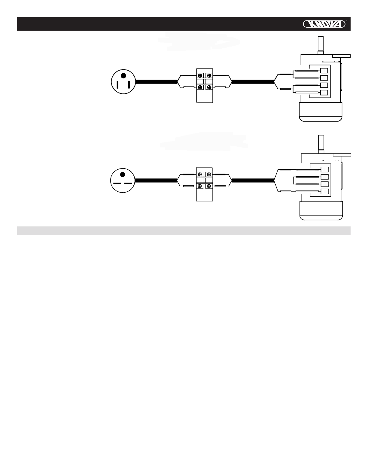
Wiring diagrams ................................................................. 4
Glossary of terms for woodworking ................................... 4
Know you machine ............................................................ 5
Assemble and adjustments ................................................ 6
Adjusting the miter gauge .................................................. 11
Assembly diagram stand .................................................... 12
Assembly diagram motor ................................................... 13
Part list of stand and motor ............................................... 14
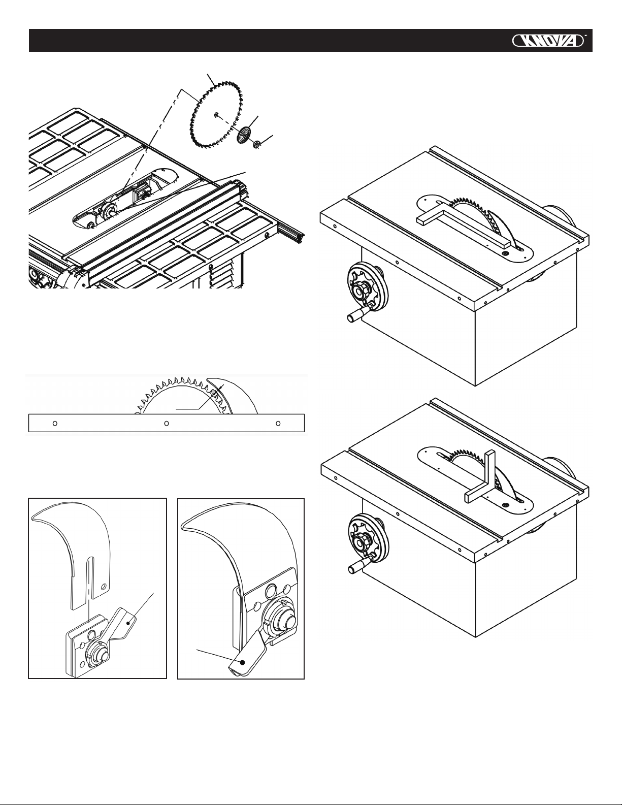
Assembly diagram blade cover .......................................... 16
Assembly diagram miter gauga .......................................... 16
Part list of blade cover and miter gauge ............................ 17
Assembly diagram of the base .......................................... 18
Assembly diagram of the table .......................................... 19
Part list of base and table .................................................. 19
PRODUCT SPECIFICATIONS
Motor:
1-1/2 H.P. 120/240 V. 60 Hz.
Idle speed: 3,450 RPM.
Arbor size: 5/8” (15.8 mm)
Saw blade: 10” (254 mm)
TABLE OF CONTENTS
1
PREFACE
Thank you for choosing this tilting arbor table saw. We are pleased to offer you our best machinery and service, and trust that you will nd
our machinery economical, productive and easy to operate.
This manual covers the proper operation, safety and maintenance of the machine. It is important that this manual be read in its entirety
before operating the machine. Although the machine has been checked and inspected in compliance with relevant safety regulations, the
machine’s safety and best performance are dependent on proper maintenance and operation. Hazards that arise due to improper operation
and maintenance are solely the responsibility of the operator.
We thank you again for you choice, and for your careful reading of this manual.
GENERAL SAFETY RULES FOR WOODWORKING MACHINERY
There is a certain amount of hazard involved with the use of woodworking machinery. Using the machine with the respect and
caution demanded as far as safety precautions are concerned will considerably lessen the possibility of personal injury.
However, if normal safety precautions are overlooked or ignored, several personal injury to the operator can occur. If you have
any questions relative to its application DO NOT use the tool until you have read what we have advised you.
1. KNOW YOUR POWER TOOL. Read the owner’s manual
carefully. Learn the tools applications and limitations,
as well as the specic potential hazards peculiar to it.
2. KEEP GUARDS IN PLACE and in working order.
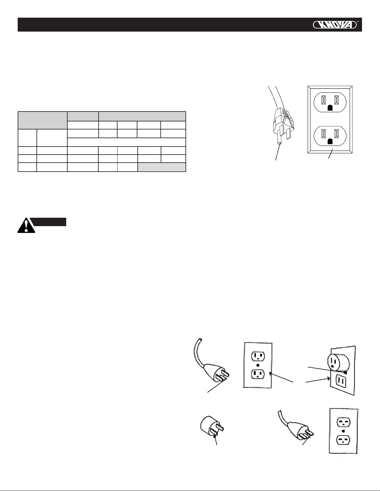
3. GROUND ALL TOOLS. If tool is equipped with
three-prong plug. It should be plugged into a three-pole
electrical receptacle. If an adapter is used to
accommodate a two-prong receptacle, the adapter lug
must be attached to known ground. Never remove
the third prong.
4. REMOVE ADJUSTING KEYS AND WRENCHES. Form
habit of checking, to see that keys and adjusting
wrenches are removed from tool before turning it on.
5. KEEP WORK AREA CLEAN. Cluttered areas and
benches invite accidents.
6. AVOID DANGEROUS ENVIRONMENT. Don’t use
power tools in damp or wet locations, or expose them to
rain. Keep work area well lighted.
7. KEEP CHILDREN AND VISITORS AWAY. All children
and visitors should be kept a safe distance from
work area.
All specication, dimensions and design characteristics shown in this catalogue are subject to change without notice.
Max. depth of cut at 90º:
3/18” (79 mm)
Max. depth of cut at 45º:
2-1/5” (56.25 mm)
Saw blade tilt left: 0º - 45º
Table size: 20-1/8” x 27”
MODEL KN RXW-10M3
8. MAKE WORKSHOP KID PROOF with padlocks, master
switch, or by removing starter keys.
9. DON’T FORCE TOOL. It will do the job better and be
safer at the rate for which it was designed.
10. USE RIGHT TOOL. Don’t force tool or attachment to do
a job for which it was not designed.
11. WEAR PROPER APPAREL. No loose clothing, gloves,
neckties, rings, bracelets, or jewelry to get caught in
moving parts. Non-slip footwear is recommended. Wear
protective hair covering to contain long hair.
12. ALWAYS USE SAFETY GLASSES. Also use face or dust
mask if cutting operation is dusty. Everyday eyeglasses
only have impact resistant lenses, they are NOT safety
glasses.
13. SECURE WORK. Use clamps or a vise to hold work,
when practical. It’s safer than using your hand and frees
both hands to operate tool.
14. DON’T OVERREACH. Keep your proper footing and
balance at all times.
Miter gauge left & right:
30º
Fence size: 36” x 1-3/4” x 2-5/8”
Overal dimensions:
49-3/4” x 41-3/4” x 38-1/8”
Net/gross weight: 103 / 114 Kg.

2
GENERAL SAFETY RULES FOR WOODWORKING MACHINERY
15. MAINTAIN TOOLS IN TOP CONDITION. Keep tools
sharp and clean for best and safest performance. Follow
instructions for lubricating and changing accessories.
16. DISCONNECT TOOLS before servicing and when
changing accessories such as blades, bits, cutters.
17. USE RECOMMENDED ACCESSORIES. Consult the
owner’s manual for recommended accessories. The use
of improper accessories may cause hazards.
18. AVOID ACCIDENTAL STARTING. Make sure switch is
in “OFF” position before plugging in cord.
19. NEVER STAND ON TOOL. Serious injury could occur if
the tool is tipped or if the cutting tool is accidentally
contacted.
1. ALWAYS use saw-blade guard and spreader for every
operation for which it can be used, including all through
sawing. Thru-sawing operations those when the blade
cuts completely through the work piece as in ripping
or cross cutting.
2. ALWAYS hold the work rmly against the miter gage
or fence.
3. ALWAYS use a push stick for ripping narrow stock. Refer
to ripping applications in instruction manual where push
stick is covered in detail.
4. NEVER perform any operation “free-hand” which means
using your hands to support or guide the work piece.
Always use either the fence or the miter gage to position
and guide the work.
5. NEVER stand or have any part of your body in line with
the path of the saw blade.
6. NEVER reach in back of or over saw blade.
7. MOVE the rip fence out of the way when cross cutting.
8. WHEN cutting molding. NEVER run the stock between
the fence and the molding cutter head. Refer to molding
applications in instruction Manual for details.
9. DIRECTION OF FEED. Feed work into a blade or cutter
against the direction or rotation of the blade or cutter
only.
TOOLS PROVIDED FOR ASSEMBLY
1. Arbor-blade guard bracket wrench.
2. 12mm combination wrench.
3. Two Allen wrenches.
20. CHECK DAMAGED PARTS. Before further use of the
tool, a guard or other part that is damaged should be
carefully checked to ensure that it will operate properly
and perform its intended function-check for alignment
of moving parts, binding of moving parts, breakage of
parts, mounting ,and any other conditions that may affect
its operation. A guard or other part that is damaged
should be properly repaired or replaced.
21. DIRECTION OF FEED. Feed work into a blade or cutter
against the direction of rotation of the blade or cutter
only.
22. NEVER LEAVE TOOL RUNNING UNATTENDED. TURN
POWER OFF. Don’t leave tool until it comes to a
complete stop.
23. NO DRUGS, ALCOHOL, MEDICATION. Do not operate
tool while under the inuence of drugs, alcohol or
any medication.
ADDITIONAL SAFETY RULES FOR TABLE SAWS
ASSEMBLY INSTRUCTION
10. NEVER use the fence as a cut-off gage when cross
cutting.
11. NEVER attempt to free a stalled saw blade without rst
turning the saw OFF.
12. PROVIDE adequate support to the rear and sides
of the saw table for wide or long work pieces.
13. AVOID KICKBACKS (work thrown back toward you)
by keeping blade sharp. Keeping rip fence parallel to
the saw blade. Keeping splitter and ant kickback gures
and guard in place and operating, by not releasing work
before it is pushed all the way past the saw blade,
and by not ripping work that is twisted or does not have
a straight edge to guide along the fence.
14. AVOID awkward operations and hand positions where
a sudden slip could cause your hand to move into
the cutting tool.
15. NEVER use solvents to clean plastic parts. Solvents
could possibly dissolve or otherwise damage
the material. Only a soft damp cloth should be
used to clean plastic parts.
16. ALWAYS bolt the saw to the supporting surface or use a
sturdy outrigger support if a table extension more than
24 in long is attached to the saw.
ADDITIONAL TOOLS REQUIRED
1. Straightedge.
2. Large slot and large Phillips screwdrivers.
3. Socket Wrench (recommended) and Adjustable wrench.

3
ELECTRICAL
EXTENSION CORDS
Use only 3-wire extension cords that have 3-prong ground-
ing plugs and 3-pole receptacles that accept the tool’s plug,
When using a power tool at a considerable distance from the
power source, use an extension cord heavy enough to carry
the current that the tool will draw. An undersized extension
cord will cause a drop in line voltage, resulting in a loss of
power and cause the motor to overheat. Use the chart pro-
vided below to determine the minimum wire size required in
an extension cord. Only round jacketed cords listed by Under-
writers Laboratories (UL) should be used.
When working with the tool outdoors, use an extension cord
that is designed for outside use. This is indicated by the let-
ters WA on the cord’s jacket.
Before using an extension cord, inspect it for loose or exposed
wires and cut or worn insulation.
ELECTRICAL CONNECTION
Your Table Saw is powered by a precision built electric motor.
Do not operate this tool on direct current(DC). A substantial
voltage drop will cause a loss of power and the motor will
overheat. If the saw does not operation when plugged into an
outlet, double check the power supply.
SPEED AND WIRING
The no-load speed of your table saw is approximately 4,000
rpm. This speed is not constant and decreases under a load
or with lower voltage. For voltage, the wiring in a shop is as
important as the motor’s horse-power rating. A line intended
only for lights cannot properly carry a power tool motor. Wire
that is heavy enough for a short distance will be too light for a
greater distance. A line that can support one power tool may
be able to support two or three tools.
GROUNDING INSTRUCTIONS
1. All ground, cord-connected tools:
In the event of a malfunction or breakdown, grounding
provides a path of least resistance for electric current to
reduce the risk of electric shock. This tool is equipped with an
electric cord having an equipment-grounding conductor and
a grounding plug. The plug must be plugged into a matching
outlet that is properly installed and grounded in accordance
with all local codes and ordinance.
Do not modify the plug provided. If it will not t the outlet,
have the proper outlet installed by a qualied electrician.
Improper connection of the equipment- grounding conductor
can result in a risk of electric shock. The conductor with
insulation having an outer surface that is green with or
without yellow stripes is the equipment of the electric cord
or plug is necessary, do not connect the equipment-grounding
conductor to a live terminal.
2. Grounded,
cord-connected tools
intended for use on a
supply circuit having a
nominal rating less
than 150V:
This tool is intended for
use on a circuit that has
an outlet that looks like
the one illustrated in
Sketch A in
Figure1.2.
The tool has a
grounding plug that looks like the plug illustrated in Sketch
A in Figure 1.2. A temporary adapter, which looks like the
adapter illustrated in Sketches B and C, may be used to
connect this plug to a 2-pole receptacle as shown in sketch B
if a properly grounded outlet is not available. The temporary
adapter should be used only until a properly grounded outlet
can be installed by a qualied electrician. The green-colored
rigid ear, lug, and the like, extending from the adapter must
be connected to a permanent ground such as a properly
grounded outlet box.
3. Grounded, cord-connected tools intended for use on a
supply circuit having a nominal rating between 150-250V,
inclusive:
This tool is intended for use on a circuit that has an outlet that
looks like the one illustrated in Sketch D in Figure 1.2. The
tool has a grounded plug that looks like the plug illustrated in
Sketch D in Figure 1.2. Make sure the tool is connected to an
outlet having the same conguration as the plug. No adapter
is available or should be used with this tool. If the tool must be
reconnected for used on a different type of electric circuit, the
reconnection should be made by qualied service personnel;
and after reconnection, the tool should comply with all local
codes and ordinances.
CAUTION
keep the cord away from the cutting area
and position the cord so that it will not be caught on
lumber, tools, or other objects during cutting operations.
More Not more
than than
6 10
10 12
12 16
Volts Total length of cord in feet
120v 25ft. 50ft. 100ft. 150ft.
240v 50ft. 100ft. 200ft. 300ft.
AWG
18 16 14 12
16 16 14 12
14 12
Not Recommended
Ampere
Rating
Check with a qualied electrician or service personnel if the
grounding instructions are not completely understood, or if in
doubt as to whether the tool is properly grounded.
Repair or replace a damaged or worm cord immediately.
This tool is intended for use on a circuit that has an outlet like
the one shown in Figure 1.1. It also has a grounding pin like
the one shown.
Grounding
pin
Grounding pin
Adapter
(A)
Fig.1.2
Fig.1.1
(B)
(C)
(D)
Grounding
pin
Grounding
means
Cove of grounded
outlet box
Metal screw
Cover of grounded
outlet box

4
WIRING DIAGRAMS
When rewiring the supplied electric motor, be sure power cord is unplugged then change the connection
as illustrated below. Always secure wire nuts with friction tap. A new plug will be required.
NOTE: The reconnection shall be made by qualied electrician or service personnel.
2. TO 220 VOLT. Open motor
wire box, contact No.1 red
motor wire to either power
wire, and contact No.4
white motor wire to another
power wire, than contact
No.2 black motor wire to
No.3 yellow motor wire.
Place refer to Fig.1.4.
Red 1
3
2
4
Yellow
Black
White
110 V
220 V
Fig.1.3
Fig.1.4
GLOSSARY OF TERMS FOR WOODWORKING
Anti-Kickback Pawls: Toothed safety devices behind the
blade designed to stop a workpiece from being kicked back
at the operator during a ripping operation.
Arbor: The shaft on which a blade or cutting
tool is mounted.
Bevel Cut: A cutting operation made with the blade at any
angle other than 90°to the saw table.
Compound Cut: A cut with both a miter angle and a bevel
angle.
Crosscut: A cutting operation made across the grain or the
width of the workpiece.
Dado A non-through cut that gives a square notch or
though; requires a special blade.
Feather board: A device to help guide workpieces during
rip cuts.
Freehand (for Table Saw): Dangerous practice of making a
cut without using rip or miter fences. See Safety Rules.
Gum: A sticky, sap-based residue from wood products.
Heel: Alignment of the blade.
Kerf: The material removed by the blade in a through cut or
the slot produced by the blade in a non-through cut.
Kickback: A hazard that can occur when blade binds or
stalls, throwing workpiece back toward operator.
Leading End: The end of the workpiece pushed into the cut-
ting tool rst.
Miter Cut: A cutting operation made with the miter gage at
any angle other than 0°.
Molding: A non-through cut that gives a varied shape to the
workpiece and requires a special blade.
Push Stick: A device used to feed the workpiece through
the saw blade during narrow cutting operations. It helps
keep the operator’s hands well away from the blade.
Rabbet: A notch in the edge of a workpiece.
Re saw: A cutting operation to reduce the thickness of the
workpiece in order to make thinner pieces.
Resin: A sticky, sap-based substance.
Rip Cut: A cut made with the grain of the workpiece.
Saw blade Path: The area directly in line with
the blade –over, under, behind, or in front of it. Also, the
workpiece area which will be or has been cut by the blade.
Set: The distance that the tip of the saw blade tooth is bent
(or set ) outward from the face of the blade.
Throw-Back: Saw throwing back a workpiece; similar to
kickback.
Through Sawing: Any cutting operation where the blade
extends completely through the workpiece.
Trailing End: The workpiece end last cut by the blade in a
rip cut.
Workpiece: The item on which the cutting operation is being
done. The surfaces of a workpiece are commonly referred to
as faces, ends, and edges.
Worktable: The surface on which the workpiece rests while
performing a cutting operation.
1. TO 110 VOLT. Open motor
wire box, contact No.1 red
motor wire and No.3 yellow
motor wire to either power
wire; than contact No.2
black motor wire and No.4
white motor wire to another
power wire. Please refer to
Fig. 1.3.
Red 1
2
3
4
Yellow
Black
White

5
KNOW YOUR MACHINE
Front
rail
Switch
Motor
cover
Rip fence
handle
Blade cover
Extension
wing
Rear rail
Miter gauge
Rip fence
Height
handwheel
Anti-kickback
pawls
Height
lock handle
Extension
wing Handle
OVERVIEW
The upper position of the blade projects up through the table,
surrounded by an insert called the thru plate. The height of
the blade is set with a hand wheel on the front of the cabinet.
To accommodate wide panels, the tabletop has extensions on
each side. Detailed instructions are provided in the Operation
section of this manual for the basic cuts: Cross cuts, miter
cuts, bevel cuts, and compound cuts.
For cuts with the blade straight up and cutting across the
grain (cross cuts or miter cuts), use the miter gage to set the
angle and push the wood into the blade. To cut with the blade
straight up, along the grain of the wood (rip cuts), use the
rip fence to guide the wood Push smaller pieces with a push
block or push stick. To tilt the blade for a bevel cut, use the
hand wheel on the side of the cabinet. A bevel scale on the
front of the cabinet shows the blades angle. Use the miter
gauge with a bevel cross cut (compound cut) and the rip fence
with a bevel rip cut. Other cuts require special attachments,
which have detailed instruction to reduce risk of injury and
ensure the best performance from your new saw.
Before attempting to use your saw, familiarize yourself with
all operating features and safety requirements of your table
saw. The saw’s features are described below .
ANTI-KICKBACK PAWLS – Kickback is a hazard in which the
workpiece is thrown back toward the operator. The toothed
pawls are designed to snag the workpiece to prevent or
reduce injury should kickback occur.
BEVEL HANDWHEEL – This hand wheel on the right side of
the cabinet tilts the blade for a bevel cut.
BEVEL SCALE – The easy–to–read scale on the front of the
work stand shows the exact blade angle.
Fig. 2-1

KNOW YOUR MACHINE
6
BLADE – This saw is provided with a 64 tooth, 10 in. steel
blade. The blade is adjusted with bevel and height hand
wheels on the cabinet. Bevel angles are locked with a handle
below the front rail.
BEVEL LOCK HANDLE – This handle, placed just under the
worktable surface on the front of the cabinet, locks the angle
setting of the blade. Be sure the handle is hanging straight
down before tilting the blade. If it is not straight down, it may
jam and bend the locking bolt.
HEIGHT HANDWHEEL – Use this hand wheel to lower and
raise the blade for adjustments or replacement. It is located
on the right of the cabinet.
MITER GAUGE – This gage aligns the wood for a crosscut.
The easy-to-read indicator shows the exact angle for a miter
cut, with positive stops at 90º and 45º .
MITER GAUGE GROOVES – The miter gage rides in these
grooves on either side of the blade.
RAILS – Front and rear rails provide support for large work
pieces and the rip fence.
RIP FENCE – A sturdy metal fence guides the workpiece and
is secured with the rip fence handle.
Grooves run along the top and sides of the rip fence for use
with optional clamps and accessories.
RIP FENCE HANDLE – The handle on the front of the rip
fence releases the rip fence or locks it in place.
RIVING KNIFE OR SPREADER – Located directly behind
the blade, it keeps cut edges from binding and supports the
blade guard.
SCALE – Found on the front rail, the easy–to–read scale pro-
vides precise measurements in rip cuts.
EXTENSIONS WINGS – Removable stamped steel exten-
sions, 12 in. By 27 in., support larger work pieces.
WARNING
1. Be sure to use only blades rated for at least
4,200 r.p.m. and recommended for use on this saw.
2. Please use the standard blade according to
the specication mark on the blade as
Fig.2-2 & Fig.2-3:
Riving knive 2.3 mm thick
for use with 10” blade
Body: 2.1 mm ~ 2.3 mm
Kerf: 2.8 mm ~ 3.5 mm
Fig. 2-2
Spreader 2.3 mm thick for
use with 10” blade
Body: 2.1 mm ~ 2.3 mm
Kerf: 2.8 mm ~ 3.5 mm
Fig. 2-3
ASSEMBLE AND ADJUSTMENTS
ASSEMBLE THE RAISING AND TILTING HANDWHEELS
AND LOCK KNOBS
1. Place the wheels in position over the raising and tilting
screws being sure to engage the slots, a (Fig.3), in back
of each wheel with the roll pins, b (Fig.3), as shown at
right.
2. Screw on lock knobs c (Fig.4), to hold wheels in place,
then attach silver handles, d (Fig.4) tightening them with
the supplied 12mm combination wrench.
3. To use rising and tilting wheels, loosen lock nuts (but not
too much or roll pins will disengage from slots), turn
wheels to desired position and retighten lock nuts. Do
not operate saw with lock nuts untightened as the blade
could move out of position. a
b
Fig. 3

Fig. 5
7
ASSEMBLE AND ADJUSTMENTS
c
d
Fig. 4
REMOVE GREASE FROM THE SAW TOP
The protective coating on the saw table top and extension
wings prevents rust from forming during shipping and storage.
Remove it by rubbing with a rag dipped in kerosene, mineral
spirits or paint thinner. (Dispose of potentially ammable sol-
vent–soaked rags according to manufacturer’s safety recom-
mendations.) A putty knife, held at to avoid scratching the
surface, may also be used to scrape off the coating followed
by clean–up with solvent. Avoid rubbing the saw’s painted
surfaces, as many solvent–based products will remove paint.
ASSEMBLE THE EXTENSION WINGS
Attach extension wings using the 6 hex head screws and
lock washers. Make screws only nger tight at rst. Use a
straightedge to ensure that wing is level with table from front
to back. Gently tap wing up or down, then tighten screws with
the supplied combination wrench, leaving the center screw
last to be tightened.
Be sure that extension wings are ush with front edge of table
and that the painted ends face out
Level here
Flush here
Fig. 6
CHECK HEELING (PARALLELING) OF THE SAW BLADE
TO THE MITER GAGE GROOVE
See Figures 7 and 8.
DO NOT loosens any screws until you have checked with a
square and made sure adjustments are necessary. Once the
screws are loosened, these items must be reset.
WARNING
Make sure the switch is off, and your saw is
unplugged. Failure to do so could result in accidental
starting, resulting in serious personal injury.
WARNING
The saw blade must be parallel to the miter gauge
groove so the wood does not bind, resulting in kickback.
You could be hit or cut.
Marked tooth
at front
Miter gage
groove
Framing square
Marked tooth Fig. 7

8
ASSEMBLE AND ADJUSTMENTS
• Lift the blade guard. Raise the blade all the way by
turning the height hand wheel.
• Mark beside one of the saw blade teeth at the front of
the blade. Place a framing square beside the blade on
the mark. Be sure the framing square is between
the teeth and at against the blade. Measure
the distance to the right miter gauge groove.
• Turn saw blade so the marked tooth is at the back.
• Move the square to the rear and again measure
the distance to the right miter gage groove.
If the distances are the same, the blade and the miter
gauge groove are parallel. No adjustments are needed.
• If the distances measured are different, adjust the table
bracket underneath the saw. See “Heeling (Paralleling)
The Saw blade To The Miter Gauge Groove”
in the Adjustments section.
CHECKING SQUARENESS OF EXTENSION
TABLES SAW TABLE
See Figure 9 and 10.
The extension wing should be checked for squatness to the
saw table for smooth operation of the rip fence and rails.
Place a square on the saw table, with the short end up and
check .The long end of the square should extend across one
of the extension wing. If the extension wing, proceed as follow
• Loosen the two hex nuts (one for each rail) securing
the front and rear rails to the extension wing.
Do not loosen hex nuts securing rails to saw table.
• Raise or lower extension wing until it is square with
the saw table.
• Tighten hex nuts securely.
• Check extension table on opposite side of blade.
Repeat the above procedure until it reaches
the Squareness. (Fig.10)
Saw table
Square
Extension wing
Fig. 9
Fig. 10 Extension wing
Square
Saw table
CHANGING THE SAW BLADE
Attention: left hand thread.
Remove the arbor nut (J) and ange (I).
Place saw blade on arbor shaft making sure teeth point down
at the front of the saw.
Reinstall ange and arbor nut and securely tighten.
Remove the locking pin (K).
Check the correct position of the raving knife in regards
to the saw blade (see the next section).
Reinstall the saw guard.
K
J
I
Fig. 8
Fig. 11

9
ASSEMBLE AND ADJUSTMENTS
MOUNTING AND ADJUST THE RIVING KNIFE
The supplied riving knife must always be used.
The riving knife has to be adjusted in such a way that over its
entire length the gap between saw blade and riving knife does
not exceed min.3 mm and max.8 mm (Fig 12).
Blade
Fig. 11
Blade
washer
Blade nut
Arbor
shaft
3-8 mm
Fig. 12
The handle(L) should keep up as Fig.13. When install
the riving knife. Then x the handle(L) by rotation after riving
knife installation as Fig.14.
L
L
Fig. 13 Fig. 14
TO ADJUST THE RIVING KNIFE:
1. Disconnect the saw from the power source.
2. Move the blade tilt to 0º (blade 90º to table)
and raise the main blade all the way up.
3. Check both sides of the blade with a straight edge
touching the teeth as shown in Figure 15:
---If the straightedge touches the riving knife
evenly on both sides, go to step 4.
---if the straightedge only touches the riving
knife on one side, go to step 5.
Fig. 15
(checking riving
knife alignment)
Fig. 16
(checking vertical
alignment)
4. Place a machinist’s square at on the table and slides
it against the riving knife as shown in Figure 16:
--- If the square lies at against the riving knife,
the riving knife is correctly adjusted.
--- If there is a gap between the square and
the riving knife, go to Step 6.
5. Loosen the riving knife center bolt and remove
the riving knife.
6. Use the set screws shown in Figure 17 to adjust
the riving knife bracket and re-install the riving knife.

ASSEMBLE AND ADJUSTMENTS
10
ASSEMMBLE THE BLADE GUARD:
1. Before installation the blade guard (N), please conrmed
Fig.18 the handle (M) keep on open as Fig.19.
4. Put down the guards(N) as Fig.20 and lock
the handle(M), then x the handle(M) as Fig.21.
Fig.17 (set screw for adjusting riving knife)
7. Repeat step 3-7 until the riving knife is centered
on the blade and aligned at 90º to the table.
8. Position the riving knife about 3mm or 1/8” away
from the nearest carbide tooth on the main blade.
9. Lock the riving knife on the safety and appropriate
position.
M
N
P
O
Fig. 18
Fig. 19
M
2. Pull up the guards as Fig.18.
3. Insert the guards on the position O & P of spreader
as Fig.18.
Fig. 20
N
M
Fig. 21
M
CHECK THE 45º SETTING.
Tilt the blade with the bevel hand wheel as far as it will go
to the left. Place the square against the blade (be sure the
square is not against one of the saw teeth). If the blade is
not at 45º, unscrew the 45º stop screw, turn the hand wheel
until the blade is correct, and tighten the screw. Recheck and
repeat it necessary.
Check that the scale indicator is at 45º.
If not, loosen the scale indicator with a screwdriver, adjust it
within the slot, and retighten the screw.

ASSEMBLE AND ADJUSTMENTS
11
A
Fig. 23
SWITCH
INSTALLATION:
Install the switch on
the location as Fig.23
with the hex. Screw
1/4” x 20UNC x 3/4”.
Lock the screw under
the Front rail, and
make sure you have
lock including star
washer A as Fig.23.
The table saw is equipped with a push-button switch that will
accept a padlock (not included) for locking the switch in the
OFF position. See Fig. 24. To safeguard your machine from
unauthorized operation and accidental starting by young
children, the use of padlock is necessary. Place the key in a
location that is inaccessible to children and others not
qualied to use the tool.
ADJUSTING THE MITER GAUGE
See Figure 25.
You can set the miter gauge
at 0º and plus or minus 45º
with the miter gauge stop
pin and adjustable stop screws.
Note: The miter gauge provides close accuracy
in angled cuts. For very close tolerances,
test cuts are recommended.
• Loosen knob and pull out on stop pin
to rotate miter gauge base past stop screws.
• Loosen the lock nut of the 0º stop screw at
the stop pin with a 8mm wrench.
• Place a 90º square against the miter gauge
rod and the miter gauge base.
• If the rod is not square, loosen the knob,
adjust the rod, and tighten the knob.
• Adjust the 0º stop screw until
it rests against the stop pin.
• Adjust the plus and minus 45º stop screws
using a 45º triangle and the steps above.
Fig. 25
Miter gauge rod
Miter gauge
base
Knob
0º adjustable
stop screw
45º adjustable
stop screw Lock nut
Fig. 22
Fig. 24

ASSEMBLY DIAGRAM STAND
12
Table saw
10
”
Sierra de mesa
(254 mm)
KN RXW-10M3

13
ASSEMBLY DIAGRAM MOTOR
Table saw
10
”
Sierra de mesa
(254 mm)
KN RXW-10M3

44 13200040 Position nut 3
45 J1340002 Scale 1
46 12300156b Steel wire 2
47 S1500212F Dust collect pipe 1
48 V13407300 Belt 1
49 13400088 Motor cover reinforcement plate 1
50 12100038 Handle 1
51 12100039 Teeth Rod 1
52 12100040 Fixed Rubber 1
53 10105056 Handle 2
54 21000030M Nut 2
55 13200032 Wheel cover 1
56 S0121600M Locking nut 1
57 S0210540 Flat washer 1
58 S0211021 Flat washer 1
59 S0021025M Hex. Screw M10 x P1.5 x 25 1
60 S0021015M Hex. Screw 2
61 S0231000M Spring washer 10 mm 1
62 S0030305M Phiillips head screw
M3 x P0.5 x 5L
3
63 C1206202A Bearing 6202 2
65 S0400530 Key 2
66 S0050606N Set screw 12
68 S0520016 Ring STW-16 1
71 S0011090M Hex bolt 1
72 S0210402 Flat washer 4
73 S0020835M
Phillips head screw M8 x P1.25 x 35
6
74 S0210516 Flat washer 12
75 S0230800M Spring washer 8mm 16
76 11105062 Washer 1
78 S0230500M Spring washer 5mm 1
79 S0030510M Phillips head screw M5 x 0.8 x 10 1
80 S0313520 Spring pin 1
81 S0211025 Flat washer 1
82 S003A001 Round head cross drill 6
83 S0100410M Hexagon screw M4 x 10 2
84 S0210401a Flat washer 1/4 x 13 x 1t 1
1 13400001 Trunnion 1
2 13400086 Mandrel bracket 1
3 13400064 Bracket Shaft 1
4 13400060 Arbor 1
5 13400078 Connection Rod 1
6 13400087 Spindle Pulley 1
7 13400085 Motor pulley 1
9 13400079 Lifting positioning tube 1
11 M1340006 Motor 1
12
S0121000Ma
Nylon Lock Nut 1
13 S0120800M Nylon Lock Nut 1
14 13400061 Wedge Support Plate 1
15 S0020815M Hex Bolt 2
16 13400014 Wedge Adjustment Block 1
17 13400029 Screw 2
18 13400025 Dust Collection Shutter 1
21 13400077 Angle Mandrel 1
22 13400069 Scale Pointer 1
23 13400010 Lifting Mandrel 1
25 13400050 Table 1
26 13400011 Mandrel xing ring 1
27 12700003b Table insert 1
28 13400003 Motor Cover 1
29 13400075 Hand Wheel 2
30 13400070 Cabinet 1
32 S009AN04 Bearing nut M20 x P1.0 1
33 13200029 Bracket 2
34 10105069Q Flange 1
35 10105068p Arbor nut 1
36 11102020M Hex. Screw w. washer 2
37 11105080 Spring 2
39 12300125J Fixed Block 1
40 12700059 Hex. Nut 1
41 12700058 Riving knife handle 1
42 12700057 Screw 1
43 11105064 Rod cap 1
PART LIST OF STAND AND MOTOR
14
Description Q’ty.
No. Part No. Description Q’ty.
No. Part No.

136 S0530035 Ring R-35 1
137 S0310210 Spring pin 1
138 S0310320 Spring pin 2
139 13400071 Spindle pulley block 1
140 13400072 Rotating head cover 1
141 20703022 Spring 1
142 13400073 Belt tension spring 1
105 S0220400 Teeth washer 1/4” 2
106 10105053G Switch cover 1
107 S0030324
Phillips head screw 3/16” x 24 x 1 1/2”
2
108 S1017W-2 Strain relief 3
109 LC1435501 Power wire 1
110 L0000037a Power wire 1
117 12700069 Anti-scratch board 1
118 S0310320 Spring pin 1
119 11105058 Rotating head 1
120 13400076 Angle handwheel gasket 1
130 13400062 Cleaver support plate xed block 1
131 13400063 Remove saw blade positioning rod 1
132 13400065 Wedge gasket 1
133 13400066 Motor board holder 1
134 13400067 Motor mount plate 1
135 13400068 Motor plate shaft 1
136 S0530035 Ring R-35 1
137 S0310210 Spring pin 1
138 S0310320 Spring pin 2
139 13400071 Spindle pulley block 1
140 13400072 Rotating head cover 1
141 20703022 Spring 1
142 13400073 Belt tension spring 1
143 S00106120m Cap screw 1
144 S0010610M Cap screw M6 x P1.0 x 10 4
145 S0230600M Spring washer 6 mm 2
146 S0010612M Cap screw M6 x 1 x 12 1
147 S0010512M Cap screw M5 x 0.8 x 12 2
149 S0300816M Cap screw M8 x P1.25 x 16 4
PART LIST OF STAND AND MOTOR
15
Description Q’ty.
No. Part No. Description Q’ty.
No. Part No.
85 S0050808M Set screw M8 x P1.25 x 8 4
86 S0110800M Hex nut M8 x P1.25 6
87 S0120600M Nylon lock nut M6 1
88 S0210405 Flat washer 1
89 S0010835M Hex bolt M8 x 35L 2
90 S0310318 Spring pin 1
91 S0020820M Screw 8
92 S0040310M Flat head screw M3 x P0.5 x 10L 2
93 S0050505M Set screw M5 x P0.8 x 5L 6
94 12300154 Push tool 1
95 10105090Q Wrench 1
96 S0911417 Open wrench 14 x 17 1
97 S0911012 Open wrench 10 x 12 1
98 S0910206 L-wrench 6mm 1
99 S0910204 L-wrench 4mm 1
100 S0910203 L-wrench 3mm 1
101 S0910225 L-wrench 2.5mm 1
102 S0030506M Phillips head screw M5 x 0.8 x 6 2
103 WG000002 Switch box 1
104 WG000007 Switch 1
105 S0220400 Teeth washer 1/4” 2
106 10105053G Switch cover 1
107 S0030324
Phillips head screw 3/16”*24*1 1/2”
2
108 S1017W-2 Strain relief 3
109 LC1435501 Power wire 1
110 L0000037a Power wire 1
117 12700069 Anti-scratch board 1
118 S0310320 Spring pin 1
119 11105058 Rotating head 1
120 13400076 Angle handwheel gasket 1
130 13400062 Cleaver support plate xed block 1
131 13400063 Remove saw blade positioning rod 1
132 13400065 Wedge gasket 1
133 13400066 Motor board holder 1
134 13400067 Motor mount plate 1
135 13400068 Motor plate shaft 1

16
ASSEMBLY DIAGRAM BLADE COVER
ASSEMBLY DIAGRAM MITER GAUGE
Table saw
10
”
Sierra de mesa
(254 mm)
KN RXW-10M3
Table saw
10
”
Sierra de mesa
(254 mm)
KN RXW-10M3

PART LIST OF BLADE COVER AND MITER GAUGE
17
Description Q’ty.
No. Part No. Description Q’ty.
No. Part No.
A1 13000004 Riving knife 1
A2 12700005 Supporting arm 1
A3 12700006 Guard (left) 1
A4 12700007 Guard (right) 1
A5 12700067 see thru plate 1
A6 10606102 Anti-back kick plate 2
A7 10103040 Spring 1
A9 S0030508M Phillip HD. screw M5 x P0.8 x 8 2
A10 S0120200 Nylon lock nut 1/4” x 20UNC 8
A11 S0040412
Flat head screw 1/4” x 20UNC x 3/4”
8
A12 S0210404 Flat washer 8
A14 S0313528 Spring pin 1
A15 S0310536 Spring pin 1
A17 12700051a Fixed sleeve 1
A18 12700039a Supporting arm block 1
A19 S0120600M Locking nut M6 x 1.0 3
A20 S0020635M Screw 2
A21 12700054 Handle 1
A22 12700061 Fixed plate 1
A24 12700062 Guard 1
A25 S0010512M Cap screw M5 x P0.8 x 12 2
A26 12700038 Supporting plate 2 4
A27 JG133001 Warning label 1
A28 S0020535M Screw 1
A29 S0210304 Flat washer 1
A30 10401005 Back spacer ring 2
A31 S0120500M Nylon lock nut M5 x P0.8 1
C1 10104046K Miter gauge body 1
C2 10104048C Miter bar 1
C3 10104045K Hand knob 1
C4 10104050G Pointer 1
C5 10104049Q Position plate 1
C6 10104047 Sloding block 1
C7 S0210501 Flat washer 5/16” x 23 x 2t 1
C8 S0030110
Phillip Hd. screw 5/32” x 32UNC x 5/8”
3
C9 S0110100 Hex. nut 5/32” 3
C10 S0050404 Set screw 1/4”-20UNC x 1/4” 1
C11 S0310306 Pin Ø3 x 6 1
C12 S0040402 Flat head screw 1
C13 10104047K Pin Ø8 x 20 mm 1

ASSEMBLY DIAGRAM OF THE BASE
18
Table saw
10
”
Sierra de mesa
(254 mm)
KN RXW-10M3

ASSEMBLY DIAGRAM OF THE TABLE AND EXTENSION WINGS
Description Q’ty.
No. Part No.
B01 11107098 Rubber Feet 4
B02 S0110500 Hex. nut M5 x P0.8 40
B03 S0210516 Flat washer 8 x 16 x 2t 48
B04 S0060509 Carriage bolt 24
B05 S0020500 Hex bolt 5/16” x 18UNC x 1/2” 8
B06 S0230506 Spring washer 36
B07 13400080 Foot stand 4
B08 13400081 Upper front and rear angle irons 2
B09 13400082 Upper left and right angle iron 2
B10 13400083 Lower front and rear angle iron 2
B11 13400084 Lower left and right angle iron 2
PART LIST OF THE BASE AND TABLE
Description Q’ty.
No. Part No.
D1 E0000004 Extension wing 2
D2 S0211021 Flat washer 10 x 21 x 2T 6
D3 S0021025M Screw 10 x 25 6
19
Table saw
10
”
Sierra de mesa
(254 mm)
KN RXW-10M3
Table of contents
Languages:
Other KNOVA Saw manuals

KNOVA
KNOVA KN SS-162 User manual

KNOVA
KNOVA KN M-2509RC User manual

KNOVA
KNOVA KN M-2504RC User manual

KNOVA
KNOVA KN M-3057R User manual

KNOVA
KNOVA KN SS-18VVS User manual

KNOVA
KNOVA KN M-2502N User manual

KNOVA
KNOVA KN SCM-05P User manual

KNOVA
KNOVA KN M-2500W User manual

KNOVA
KNOVA KN BTS-10W User manual

KNOVA
KNOVA KN M-3059R User manual
Popular Saw manuals by other brands

Powersmart
Powersmart PS3030 instruction manual

Central Pneumatic
Central Pneumatic 62541 owner's manual

woodmizer
woodmizer LT60 Safety, Installation, Operation, Maintenance & Parts Manual

Craftsman
Craftsman 113.244530 owner's manual

WorkPro
WorkPro W125018A Original operating instructions

Hyd-Mech
Hyd-Mech H-40 Operation and maintenance manual