KNOVA KN M-2500W User manual

KN M-2500W
10
”
(254 mm)
Compound miter saw
Sierra angular compuesta

Product specifications ......................................................... 1
Power tool safety ................................................................. 1
Compound Miter Saw Safety ............................................... 2
Electrical requirements and safety ...................................... 3
Accessories and Attachments ............................................. 4
Tools Needed for Assembly
Carton Contents
Know Your Compound Miter Saw ...................................... 5
Glossary of Terms ............................................................... 6
Assembly and adjustments ................................................ 6
Operation ........................................................................... 10
Maintenance ...................................................................... 13
Troubleshooting guide ....................................................... 14
Parts list ............................................................................. 15
PRODUCT SPECIFICATIONS
POWER TOOL SAFETY:
1. READ and become familiar with the entire Operator’s Man-
ual. LEARN the tool’s application, limitations and possible
hazards.
2. KEEP GUARDS IN PLACE and in working order.
3. REMOVE ADJUSTING KEYS AND WRENCHES. Form the
habit of checking to see that keys andadjusting wrenches are
removed from the tool before turning ON.
4. KEEP WORK AREA CLEAN. Cluttered areas and benches
invite accidents.
5. DO NOT USE IN DANGEROUS ENVIRONMENTS. Do not
use power tools in damp locations, or expose them to rain or
snow. Keep work area well lit.
6. KEEP CHILDREN AWAY. All visitors and bystanders should
be kept a safe distance from work area.
TABLE OF CONTENTS
1
WARNING
Some dust created by power sanding, sawing, grinding, drilling and other construction activities contains chemicals
(known to the State of California) to cause cancer, birth defects or other reproductive harm. Some examples of these
chemicals are:
•Lead based paints
•Crystalline silica from bricks, cement and other masonry products
•Arsenic and chromium from chemically treated lumber
Your risk from these exposures varies, depending on how often you do this type of work. To reduce your exposure to
these chemicals, work in a well-ventilated area and work with approved safety equipment, such as dust masks that
are specially designed to filter out microscopic particles.
MOTOR
Power Source ...................... 120V AC, 60Hz, 15 Amp
Arbor Shaft Size .................. 5/8 in.
Speed .................................. 4800 RPM (No load)
Brake ................................... Electric
Double Insulated .................. Yes
MITER SAW
Cutting Capacity:
Crosscut ............................... 2-5/8 in. x 5-1/2 in.
Miter 45° R & L ..................... 2-5/8 in. x 3-1/2 in.
Bevel 45° L ............................... 1-9/16 in. x 5-1/2 in. L
45° Miter and 45° Bevel ............ 1-9/16 in. x 3-1/2 in.
Rotating Table:
Miter Detent Stops .................... 0°, 15°, 22.5°, 31.6°, 45° R & L
Bevel Positive Stops ................. 0°, 45° L
GENERAL SAFETY INSTRUCTIONS
WARNING
To avoid electrical hazards, fire hazards or damage to the tool, use proper circuit protection.
This tool is wired at the factory for 110-120 Volt operation. It must be connected to a 110-120 Volt / 15 Ampere time
delay fuse or circuit breaker. To avoid shock or fire, replace power cord immediately if it is worn, cut or damaged in
any way.
Before using your tool, it is critical that you read and understand these safety rules. Failure to follow these rules could
result in serious injury to you or damage to the tool.
WARNING
To avoid mistakes that could cause serious injury, do
not plug the tool in until you have read and understood
the following.
Safety is a combination of common sense, staying alert and
knowing how to use your power tool.

SPECIFIC SAFETY INSTRUCTIONS FOR THIS COMPOUND
MITER SAW
1. DO NOT USE THIN KERF BLADES they can deflect and con-
tact guard and can cause possible injury to the operator.
2. DO NOT operate the miter saw until it is completely assem-
bled and installed according to these instructions.
3. IF YOU ARE NOT thoroughly familiar with the operation of
miter saws, seek guidance from your supervisor, instructor or
other qualified person.
4. ALWAYS hold the work firmly against the fence and table. DO NOT
perform any operation free hand (use clamp wherever possible).
5. KEEP HANDS out of the path of the saw blade. If the work-
piece you are cutting would cause your hands to be within 6-3/4
in. of the saw blade, the workpiece should be clamped in place
before making the cut.
6. BE SURE the blade is sharp, runs freely and is free of vibra-
tion.
7. ALLOW the motor to come up to full speed before starting a cut.
8. KEEP THE MOTOR AIR SLOTS CLEAN and free of chips or dust.
9. ALWAYS MAKE SURE all handles are tight before cutting,
even if the table is positioned in one of the positive stops.
10. BE SURE both the blade and the collar are clean and the
arbor bolt is tightened securely.
11. USE only blade collars specified for your saw.
12. NEVER use blades larger in diameter than 10 inches.
13. NEVER apply lubricants to the blade when it is running.
14. ALWAYS check the blade for cracks or damage before opera-
tion. Replace a cracked or damaged blade immediately.
15. NEVER use blades recommended for operation at less than
4800 RPM.
16. ALWAYS keep the blade guards in place and use at all times.
COMPOUND MITER SAW SAFETY
2
7. MAKE WORKSHOP CHILD PROOF with padlocks, master
switches or by removing starter keys.
8. DO NOT FORCE THE TOOL. It will do the job better and
safer at the rate for which it was designed.
9. USE THE RIGHT TOOL. Do not force the tool or an attach-
ment to do a job for which it was not designed.
10. USE PROPER EXTENSION CORDS. Make sure your ex-
tension cord is in good condition. When using an extension
cord, be sure to use one heavy enough to carry the current
your product will draw. An undersized cord will result in a
drop in line voltage and in loss of power which will cause the
tool to overheat. The table on page 5 shows the correct size to
use depending on cord length and nameplate ampere rating.
If in doubt, use the next heavier gauge. The smaller the gauge
number, the heavier the cord.
11. WEAR PROPER APPAREL. Do not wear loose clothing,
gloves, neckties, rings, bracelets or other jewelry which may
get caught in moving parts. Nonslip footwear is recommend-
ed. Wear protective hair covering to contain long hair.
12. ALWAYS WEAR EYE
PROTECTION. Any power tool
can throw foreign objects into
the eyes and could cause
permanent eye damage.
ALWAYS wear Safety Goggles
(not glasses) that comply with
ANSI Safety standard Z87.1
Everyday eyeglasses have only impact–resistant lenses. They
ARE NOT safety glasses. NOTE: Glasses or goggles not in
compliance with ANSI Z87.1 could seriously injure you when
they break.
13. WEAR A FACE MASK OR DUST MASK. Sawing opera-
tion’s produce dust.
14. SECURE WORK. Use clamps or a vise to hold work when
practical. It is safer than using your hand and it frees both
hands to operate the tool.
15. DISCONNECT TOOLS FROM POWER SOURCE before
servicing and when changing accessories such as blades bits
and cutters.
16. REDUCE THE RISK OF UNINTENTIONAL STARTING. Make
sure switch is in the OFF position before plugging the tool in.
17. USE RECOMMENDED ACCESSORIES. Consult this Opera-
tor’s Manual for recommended accessories. The use of improper
accessories may cause risk of injury to yourself or others.
18. NEVER STAND ON THE TOOL. Serious injury could oc-
cur if the tool is tipped or if the cutting tool is unintentionally
contacted.
19. CHECK FOR DAMAGED PARTS. Before further use of the
tool, a guard or other part that is damaged should be carefully
checked to determine that it will operate properly and perform
its intended function – check for alignment of moving parts,
binding of moving parts, breakage of parts, mounting and any
other conditions that may affect its operation. A guard or other
part that is damaged should be properly repaired or replaced.
20. NEVER LEAVE THE TOOL RUNNING UNATTENDED.
TURN THE POWER “OFF”. Do not walk away from a running
tool until the blade comes to a complete stop and the tool is
unplugged from the power source.
21. DO NOT OVERREACH. Keep proper footing and balance
at all times.
22. MAINTAIN TOOLS WITH CARE. Keep tools sharp and
clean for best and safest performance. Follow instructions for
lubricating and changing accessories.
23. WARNING: Dust generated from certain materials can be
hazardous to your health. Always operate saw in well-venti-
lated area and provide for proper dust removal.
POWER TOOL SAFETY:

17. NEVER reach around the saw blade.
18. MAKE SURE the blade is not contacting the workpiece be-
fore the switch is turned ON.
19. IMPORTANT: After completing the cut, release the trigger
and wait for the blade to stop before returning the saw to the
raised position.
20. MAKE SURE the blade has come to a complete stop before
removing or securing the workpiece, changing the workpiece
angle or changing the angle of the blade.
21. NEVER cut metals or masonry products with this tool. This
miter saw is designed for use on wood and wood-like products.
22. NEVER cut small pieces. If the workpiece being cut would
cause your hand or fingers to be within 6-3/4 in. of the saw blade
the workpiece is too small.
23. PROVIDE adequate support to the sides of the saw table for
long work pieces.
24. NEVER use the miter saw in an area with flammable liquids
or gases.
25. NEVER use solvents to clean plastic parts. Solvents could
possibly dissolve or otherwise damage the material.
26. SHUT OFF the power before servicing or adjusting the tool.
27. DISCONNECT the saw from the power source and clean the
machine when finished using.
28. MAKE SURE the work area is clean before leaving the ma-
chine.
29. SHOULD any part of your miter saw be missing, damaged, or
fail in any way, or any electrical component fail to perform prop-
erly, lock the switch and remove the plug from the power supply
outlet. Replace missing, damaged, or failed parts before resum-
ing operation.21. DO NOT perform lay out assembly or set up
work on the table while the drill press is in operation.
ELECTRICAL REQUIREMENTS AND SAFETY
3
COMPOUND MITER SAW SAFETY
ELECTRICAL REQUIREMENTS – cont’d
DOUBLE INSULATED
The power tool is double insulated to provide a double thick-
ness of insulation between you and tool’s electrical system. All
exposed metal parts are isolated from the internal metal motor
components with protecting insulation.
Replacement parts – When servicing, use only identical re-
placement parts.
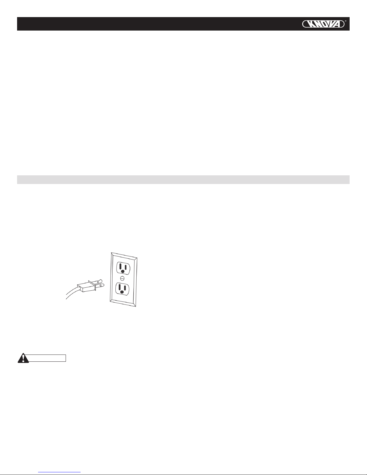
Polarized plugs – This saw has a plug that looks like the one
shown below:
To reduce the risk of electrical shock, this saw has a polarized
plug (one blade is wider than the other). This plug will fit in a
polarized outlet only one way. If the plug does not fit fully in the
outlet, reverse the plug. If it still does not fit, contact a qualified
electrician to install the proper outlet. Do not change the plug
in any way.
Double insulation does not take the place of normal safety pre-
cautions when operating this tool. To avoid electrocution:
1. Use only identical replacement parts when servicing a tool
with double insulation. Servicing should be performed by a
qualified technician.
2. Do not use power tools in wet or damp locations or expose
them to rain or snow.
MOTOR SAFETY PROTECTION IMPORTANT
To avoid motor damage, the motor should be blown out or vacu-
umed frequently to keep sawdust from interfering with the mo-
tor ventilation.
1. Connect this saw to a 120 V circuit. This circuit must not be
less than a #12 wire with a 20 A time lag fuse or a #14 wire
with a 15 A time lag fuse.
NOTE: When using an extension cord on a circuit with a
#14 wire, the extension cord must not exceed 25 feet in
length.
2. If the motor will not start, release the trigger switch
immediately. UNPLUG THE SAW. Check the saw blade to
make sure it turns freely. If the blade is free, try to start the
saw again. If the motor still does not start, refer to the
TROUBLESHOOTING GUIDE.
3. If the tool suddenly stalls while cutting wood, release the
trigger switch, unplug the tool and free the blade from the
wood. The saw may now be started and the cut finished.
4. FUSES may “blow” or circuit breakers may trip frequently if:
a. MOTOR is overloaded – overloading can occur if you
feed too rapidly or make too many start/stops in a short
time.
b. LINE VOLTAGE is more than 10% above or below the
nameplate voltage rating. For heavy loads, the voltage at
motor terminals must equal the voltage specified on the
nameplate.
c. IMPROPER or dull saw blades are used.
5. Most motor troubles may be traced to loose or incorrect
connections, overload, low voltage or inadequate power
supply wiring. Always check the connections, the load and
supply circuit if the motor doesn’t run well. Check minimum
gauge for the length of cord you are using on the chart
below.
GUIDELINES FOR EXTENSION CORDS
Use a proper extension cord. Make sure your extension cord
is in good condition. When using an extension cord, be sure
to use one heavy enough to carry the current your product
will draw. An undersized cord will cause a drop in line volt-
age, resulting in loss of power and overheating. The table be-
low shows the correct size to use depending on cord length
and nameplate ampere rating. If in doubt, use the next heavier
gauge. The smaller the gauge number, the heavier the cord.
WARNING

4
MINIMUM GAUGE FOR EXTENSION CORDS (AWG)
(When using 120 volts only)
Ampere Rating Total length of Cord
More Than Not More Than 25ft. 50ft. 100ft. 150ft.
0 6 18 16 16 14
6 10 18 16 14 12
10 12 16 16 14 12
12 16 14 12 Not Recommended
ELECTRICAL REQUIREMENTS AND SAFETY
Be sure your extension cord is properly wired and in good
condition. Always replace a damaged extension cord or
have it repaired by a qualified person before using it. Pro-
tect your extension cords from sharp objects, excessive
heat and damp or wet areas.
Use a separate electrical circuit for your tools. This circuit
must not be less than a #12 wire with a 20 A time lag fuse
or a #14 wire with a 15 A time lag fuse.
NOTE: When using an extension cord on a circuit with a
#14 wire, the extension cord must not exceed 25 feet in
length. Before connecting the tool to the power line, make
sure the switch is in the OFF position and the electric cur-
rent is rated the same as the current stamped on the mo-
tor nameplate, running at a lower voltage will damage the
motor.
CAUTION In all cases, make certain the receptacle
is properly grounded. If you are not sure, have a
qualified electrician check the receptacle.
ACCESSORIES AND ATTACHMENTS
RECOMMENDED ACCESSORIES
•Useonlyaccessoriesrecommendedforthismitersaw.
Follow instructions that accompany accessories. Use of
improper accessories may cause hazards.
•The use of any cutting tool except 10 in. saw blades which
meet the requirements under recommended accessories is
prohibited. Do not use accessories such as shaper cutters
or dado sets. Ferrous metal cutting and the use of abrasive
wheels is prohibited.
•Donot attempt to modify this tool or create accessories not
recommended for use with this tool. Any such alteration or
modification is misuse and could result in a hazardous
condition leading to possible serious injury.
WARNING
ACCESSORIES
Visit your Knova Hardware Department or see the Knova Power
and Hand Tool Catalog to purchase recommended accessories
for this power tool.
To avoid the risk of personal injury, do not modify this power
tool or use accessories not recommended by Knova.
Read warnings and conditions on your CARBIDE TIPPED SAW
BLADE. Do not operate the saw without the proper saw blade
guard in place. Carbide is a very hard but brittle material. Care
should be taken while mounting, using, and storing carbide
tipped blades to prevent accidental damage. Slight shocks,
such as striking the tip while handling, can seriously damage
the blade. Foreign objects in the workpiece, such as wire or
nails, can also cause tips to crack or break off. Before using,
WARNING
WARNING
TOOLS NEEDED FOR ASSEMBLY
COMBINATION SQUARE MUST BE TRUE
Should not gap or overlap when square is flipped over (see
dotted figure).
Supplied Not supplied
Blade wrench
(supplied) Adjustable wrench
Hex Key 2.5mm
Combination square
Screwdriver Phillips
Draw light line on
board along this edge.
Straight edge or a 3/4 in. board, this
edge must be perfectly straight.
Gap from untrue square
when flipped over.

5
CARTON CONTENTS
KNOW YOUR COMPOUND MITER SAW
UNPACKING YOUR MITER SAW
To avaoid injury from unexpected starting or electrical shock, do
not plug the power cord into a source of power during unpack-
ing and assembly. This cord must remain unplugged whenever
you are working on the saw.
1. Remove the miter saw from the carton.
IMPORTANT: Do not lift miter saw by the Trigger Switch
handle. It may cause misalignment.
2. Place the saw on a secure stationary work surface.
3. Separate all parts from the packing material. Check each
one with the illustration to make certain all items are
accounted for, before discarding any packing material.
If any part is missing or damaged, do not attempt to assemble
the miter saw, or plug in the power cord until the missing or
damaged part is correctly replaced. To avoid electric shock,
use only identical replacement parts when servicing double in-
sulated tools. Call Knova for replacement parts.
WARNING
WARNING
Miter saw
Dust bag
Blade wrench
Hold-down clamp Miter handle
Upper blade guard
Cover plate
Dust
bag
Laser
guide
Bevel scale
Hold-down
clamp
Base
Switch handle
ON/OFF
trigger switch
Lower
blade
guard
Motor
Blade
Miter Scale
Positive Stop
Locking Lever
Miter
Handle
Stop latch
Pivot bolt
lock nut
Arbor
Lock
Table
Table
insert Positive
miter detents Mounting
hole
Hand
hold for
transportation
Fence

GLOSSARY OF TERMS
6
COMPOUND MITER SAW TERMS
ARBOR LOCK – Allows the user to keep the blade from rotat-
ing while tightening or loosening the arbor bolt during blade
replacement or removal.
BASE – Supports the table, holds accessories and allows for
workbench or leg set mounting.
BEVEL LOCKING HANDLE – Locks the miter saw at a desired
bevel angle.
BEVEL SCALE – To measure the bevel angle of the saw blade
0° to 45° left.
COVER PLATE SCREW – Loosen this screw and rotate the
plate for access to the blade arbor bolt.
FENCE – Helps to keep the workpiece from moving when saw-
ing. Scaled to assist with accurate cutting.
LOWER BLADE GUARD – Helps protect your hands from the
blade in the raised position, it retracts as the blade is lowered.
MITER HANDLE – Used to rotate the table, and to rotate the
saw to a right or left cutting position.
MITER SCALE –
Measures the miter angle 0° to 45° left and right.
MOUNTING HOLES –
To mount the miter saw to a stable surface.
ON/OFF TRIGGER SWITCH – To start the tool, squeeze the
trigger. Release the trigger to turn off the miter saw.
POSITIVE STOP LOCKING LEVER – Locks the miter saw at a
preset positive stop for the desired miter angle.
STOP LATCH – Locks the miter saw in the lowered position
for compact storage and transportation.
SWITCH HANDLE – The switch handle contains the trigger
switch and the laser on/off switch. The blade is lowered into
the workpiece by pushing down on the handle. The saw will
return to its upright position when the handle is released.
WARNING LABELS – Read and understand for your own safe-
ty. Make sure all labels are present on machine and legible.
WRENCH STORAGE – Convenient storage to prevent mis-
placing the blade wrench.
WOODWORKING TERMS
ARBOR – The shaft on which a blade is mounted.
BEVEL CUT
– An angle cut made through the face of the workpiece.
COMPOUND CUT – A simultaneous bevel and miter cut.
CROSS CUT – A cut made across the width of the workpiece.
FREEHAND – Performing a cut without using a fence (guide),
hold down or other proper device to prevent the workpiece
from twisting during the cutting operation.
GUM – A sticky sap from wood products.
HEEL – Misalignment of the blade.
KERF – The amount of material removed by blade cut.
MITER CUT –
An angle cut made across the width of the workpiece.
RESIN – A sticky sap that has hardened.
REVOLUTIONS PER MINUTE (RPM) – The number of turns
completed by a spinning object in one minute.
SAW BLADE PATH – The area of the workpiece or table top
directly in line with the travel of the blade or the part of the
workpiece which will be cut.
SET – The distance between two saw blade tips, bent outward
in opposite directions to each other. The further apart the tips
are, the greater the set.
WORKPIECE – The item being cut. The surfaces of a work-
piece are commonly referred to as faces, ends and edges.
ASSEMBLY AND ADJUSTMENTS
SAW BLADE WRENCH (FIG. B)
1. For convenient storage and prevention of loss, there is a
slot (1) in the rear of the cutting head handle (2) for storing the
blade wrench (3) when not in use.
CUTTING HEAD (FIG. C)
Raising
1. Push down slightly on the cutting handle (1).
2. Pull out the stop latch knob (2).
3. Pull up the cutting head (3) slightly to raise to the up
position.
To avoid injury and damage to the saw, transport or store the
miter saw with the cutting head locked in the down position.
Never use the stop latch to hold the cutting head in a down
position for cutting operations.
Fig. A
Fig. C
INSTALLING THE MITER HANDLE (FIG. A)
1. Thread the miter handle (1) into the hole (2) located at the
front of the miter table.
Fig. B
WARNING

Fig. D
ASSEMBLY AND ADJUSTMENTS
Locking
When transporting or storing the miter saw, the cutting head
should always be locked in the down position.
1. Push the cutting head (3) down to its lowest position.
2. Push the stop latch (2) into the locking hole (4).
IMPORTANT: To avoid damage, never carry the miter saw
by the switch handle, the cutting arm or the miter handle.
ALWAYS use the designated carrying handle.
INSTALLING THE DUST BAG (FIG. D)
1. Squeeze the metal collar wings (2) of the dust bag (1).
2. Place the dust bag neck opening around the exhaust port
(3), and release the metal collar wings.
7
REMOVING OR INSTALLING THE BLADE
Only use a 10-inch diameter blade.
To avoid injury from an accidental start, make sure the switch
is in the OFF position and plug is not connected to the power
source outlet.
REMOVING (Fig. E, F , G)
1. Unplug the saw from the outlet.
2. Allow the cutting head to rise to the upright position.
Raise the lower blade guard (1) to the up position. (Fig. E)
3. Loosen the cover plate screw (2) with a Phillips
screwdriver.
4. Rotate the cover plate (3) towards the rear of the tool to
expose the arbor bolt (4).
5. Place the blade wrench over the arbor bolt.
Fig. E
6. Locate the arbor lock (5) on the motor, below the miter
saw switch handle. (Fig. F)
7. Press the arbor lock, holding it in firmly while turning the
blade wrench clockwise. The arbor lock will engage after
turning the wrench. Continue to hold the arbor lock in to
keep it engaged, while turning the wrench clockwise to
loosen the arbor bolt.
8. Remove the arbor bolt (4), outer blade collar (6), and the
blade (7). Do not remove the inner blade collar. (Fig. G)
NOTE: Pay attention to the pieces removed, noting their posi-
tion and direction they face. Wipe the blade collars clean of
any sawdust before installing the new blade.
Fig. F
Fig. G
WARNING
INSTALLING THE BLADE (FIG. E, F, G)
Unplug the miter saw before changing/installing the blade.
1. Install a 10 in. blade, making sure the rotation arrow on
the blade matches the clockwise rotation arrow on the
upper guard, and the blade teeth are pointing downward.
2. Place the outer blade collar (6) against the blade and on
the arbor. Thread the arbor bolt (4) into the arbor
counterclockwise. (Fig. G)
IMPORTANT: Make sure the flats of the blade collars are
engaged with the flats on the arbor shaft.
3. Place the blade wrench on the arbor bolt.
4. Press the arbor lock (5), holding it in firmly while turning
the blade wrench counterclockwise. When it engages,
continue to press the arbor lock in, while tightening the
arbor bolt securely. (Fig. F)

8
ASSEMBLY AND ADJUSTMENTS
ADJUSTING FENCE SQUARENESS (FIG. I)
1. Loosen the two fence locking bolts (1).
2. Lower the cutting arm and lock in position.
3. Using a square, lay the heel of the square against the
blade, and the rule against the fence (2) as shown. Check
to see if the fence is 90° to the blade.
4. If not, adjust fence 90° to the blade and tighten the fence
locking bolts.
CAUTION: If the saw has not been used recently, recheck
blade squareness to the fence and readjust if needed.
Fig. H
5. Rotate the cover plate (3) back until the slot in the cover
plate engages with the cover plate screw (2). Tighten the
screw with a Phillips screwdriver. Lower the blade guard.
6. Be sure the arbor lock is released so the blade turns freely.
WARNING
•Toavoidinjury,neverusethesawwithoutthecoverplate
secure in place. It keeps the arbor bolt from falling out if it
accidentally loosens, and helps prevent the spinning blade
from coming off the saw.
•Makesurethecollarsarecleanandproperlyarranged.
Lower the blade into the table and check for any contact
with the metal base or the turn table.
INSTALLING THE HOLD-DOWN CLAMP ASSEMBLY (FIG. H)
1. Loosen the lock knob (3) from the rear side of the saw base (4).
2. Place the hold-down clamp assembly (1) in one of the
mounting holes (2).
3. Tighten the lock knob (3).
ADJUSTMENT INSTRUCTIONS
To avoid injury from an accidental start, make sure the switch
is in the OFF position and the plug is not connected to the
power source outlet.
WARNING
Fig. I
MITER SCALE (FIG. J)
The miter scale assists the user in setting the desired miter
angles from 47° left to 47° right. The miter saw table has nine
of the most common angle setttings with positive stops at 0°,
15°, 22.5°, 31.6°, and 45°. These positive stops position the
blade at the desired angle quickly and accurately.
To Adjust the Angle:
1. Unlock the miter table by turning the miter handle (1)
counterclockwise.
2. Press down the positive stop locking lever (2) while
holding the miter handle, and rotate the table left or right
to the desired angle.
3. Release positive stop locking lever. Tighten miter handle.
To Adjust the Indicator:
1. Position the miter table at zero degrees.
2. Loosen the pointer screw (4) and adjust the indicator (3) to
the 0° mark on the miter scale (5) and retighten the screw.
Fig. J
CUTTING ARM TRAVEL (FIG. K)
Cutting arm pivot adjustment
The up and down pivot movement of the cutting arm (1) should
not be too tight, restricting movement, nor too loose, affect-
ing the accuracy of the saw cut. The correct adjusting nut (2)
adjustment is snug, allowing no side-toside arm movement. To
adjust, tighten or loosen the adjusting nut (2).

ASSEMBLY AND ADJUSTMENTS
9
Fig. K
Cutting head downward travel adjustment (Fig. L)
To avoid injury from unexpected starting or electrical shock,
turn the switch OFF and remove the power cord from the pow-
er source.
NOTE: Before each cutting operation, check the position of
the blade to make sure it does not contact any metal surface.
If the blade contacts any metal surface, the depth of travel
must be adjusted.
1. Lower the blade as far as possible.
2. Loosen the locknut (3).
3. Turn the adjustment bolt (4) out (counterclockwise) to
decrease the cutting depth or in (clockwise) to increase
the cutting depth.
4. Rotate the blade manually to check for contact.
5. Repeat until adjusted properly, and tighten the locknut to
secure the adjustment bolt into position.
WARNING
Fig. L
BEVEL STOP ADJUSTMENT (FIG. M & O)
To avoid injury from unexpected starting or electrical shock,
make sure the trigger is released and remove the power cord
from the power source. 90°(0°) Bevel adjustment (Fig. M)
1. Loosen bevel lock handle (1) and tilt the cutting arm
completely to the right. Tighten the bevel lock handle.
Lower blade.
2. Place a combination square (2) on the miter table with the
rule against the table and the heel of the square against
the saw blade.
3. If the blade is not 90°(0°) square with the miter table,
loosen the bevel lock handle, tilt the cutting head
completely to the left, loosen the locknut (4) on the bevel
angle adjustment bolt (3) and use a 10 mm wrench to
adjust the bolt (3) in or out to increase or decrease the
bevel angle.
4. Tilt the cutting arm to back to the right at 90°(0°) bevel and
recheck for alignment.
5. Repeat steps 1 through 4 if further adjustment is needed.
6. Tighten bevel lock handle and locknut (4) when alignment
is achieved.
Fig. M
90°(0°) Bevel indicator (Fig. N)
1. When the blade is exactly 90°(0°) to the table, loosen the
bevel indicator screw (5) using a #2 Phillips screwdriver.
2. Adjust bevel indicator (6) to the “0” mark (7) on the bevel
scale and retighten the screw.
Fig. N
45° Bevel adjustment (Fig. O)
1. Unlock the bevel lock handle and tilt the cutting arm as far
to the left as possible.
2. Using a combination square, check to see if the blade
angle is 45° to the table.
3. If the blade is not at 45° to the miter table, tilt the cutting
arm to the right, loosen the locknut (5) on the bevel angle
adjustment bolt (4) and use a 10 mm wrench to adjust the
bolt (4) in or out to increase or decrease the bevel angle.
4. Tilt the cutting arm to the left to 45° bevel and recheck
for alignment.
5. Repeat steps 1 through 4 until the blade is at 45° to the
miter table.
6. Tighten bevel lock handle and locknut (5) when alignment
is achieved.
WARNING

ASSEMBLY AND ADJUSTMENTS
10
ALIGNING THE LASER BEAM (FIG. P, Q)
For your own safety, never connect the plug to power source
outlet until all the adjustment steps are complete and you have
read and understood the safety and operational instructions.
The laser beam must always be correctly aligned with the
blade to ensure straight, even cutting.
Your tool is equipped with the laser cutting guide using Class
II laser beam. The laser beam will enable to preview the saw
blade path on the stock to be cut before starting the miter
saw. This laser guide is powered by the transformed alternat-
ing current supply directly through the power lead. The saw
must be connected to the power source and the laser on/off
switch must be turned on for the laser line to show.
AVOID DIRECT EYE CONTACT
•Laserradiatedwhenlaserguideisturnedon.
Avoid direct eye contact. Always un-plug the miter saw
from power source before making any adjustments.
•LaserWarningLabel:Maxoutput<1mWDIODE
LASER: 630-670nm, Complies with 21CFR 1040.10
and 1040. 11.
•CAUTION-Useofcontrolsoradjustmentsorperformance
of procedures other than those specified herein may result
in hazardous radiation exposure.
•CAUTION-Theuseofopticalinstrumentswiththisproduct
will increase eye hazard.
•
Do not attempt to repair or disassemble the laser. If unqualified
persons attempt to repair this laser product, serious injury may
result. Any repair required on this laser product should be
performed by authorized service center personnel.
WARNING
WARNING
Fig. O
NOTE: All the adjustments for the operation of this machine
have been completed at the factory. Due to normal wear and
use, some occasional readjustments may be necessary.
A. Check Laser Beam Alignment.
1. Mark a 90° straight line across a board to serve as a
“pattern line” to test laser alignment. Lay the board on the
miter table.
2. Plug saw into outlet and turn on the laser beam and line it
up with the pattern line.
3. Lower saw blade to pattern line and if blade is not flush
with the pattern line, adjust as follows in procedure (B).
B. Adjusting the Angle of the Laser Guide (Fig. Q)
1. Turn the laser element (2) in the desired direction to adjust
the laser angle. NOTE: Do not adjust the laser more than
¼ turn in either direction as this may damage the laser.
There are two flat sides on the laser element where you
can position an adjustable wrench for your adjustment.
C. Aligning The Laser Beam
1. Loosen only ½ turn at a time the four set screws (1).
2. Adjust laser by turning the left side set screws clockwise
to shift the laser line to the right. To shift the laser line to
the left, turn the right side set screws ½ turn at a time.
3. Once alignment of the laser is achieved, tighten only ½
turn at a time the four set screws (1).
Fig. P
Laser switch
Left side view
Right side view

ASSEMBLY AND ADJUSTMENTS
11
MOUNTING THE MITER SAW (FIG. R)
To avoid injury from unexpected saw movement:
•Beforemovingthesaw,disconnectthepowercordfrom
the outlet, and lock the cutting arm in the lower position
using the stop latch.
NOTE: The stop latch is for carrying or storing the tool. It is
not to be used for holding the saw while cutting. Lower blade
and press in stop latch to secure saw for
transport or storage.
•Never carry the miter saw by the power cord or by the switch
handle. Carrying the tool by the power cord could cause dam-
age to the insulation or wire connections resulting in electric
shock or fire.
• To avoid injury from ying debris, do not allow visitors to
stand behind the saw.
•Placethesawonarm,levelwork-surfacewherethereis
room for handling and properly supporting the workpiece.
•Supportthesawonalevelworksurface.
•Boltorclampthesawtoitssupport.
Fig. Q
Fig. R
Place the saw in the desired location, either on a work bench
or recommended leg set. The base of the saw has three
mounting holes (1).
For stationary use, fasten the saw to a workbench. For
portable use, fasten the saw to a 3/4 in. piece of plywood. This
mounting board can then be clamped to a secure surface.
OPERATION
SAFETY INSTRUCTIONS FOR BASIC SAW OPERATION
BEFORE USING THE MITER SAW
To avoid mistakes that could cause serious, permanent injury,
do not plug the tool in until the following steps are completed:
•Completelyassembleandadjustthesaw,followingthe
instructions. (ASSEMBLY AND ADJUSTMENTS)
•LearntheuseandfunctionoftheON/OFFtriggerswitch,
on/off switch for laser, upper and lower blade guards, stop
latch, bevel lock handle, and cover plate screw.
•Reviewandunderstandallsafetyinstructionsand
operating procedures in this Operator’s Manual. (SAFETY
& OPERATIONS)
•ReviewtheMAINTENANCEandTROUBLESHOOTING
GUIDE for your miter saw.
•Toavoidinjuryorpossibledeathfromelectricalshock:
Make sure your fingers do not touch the plug’s metal
prongs when plugging or unplugging your miter saw.
(ELECTRICAL REQUIREMENTS AND SAFETY) BEFORE
EACH USE INSPECT YOUR SAW.
•Disconnectthemitersaw.Toavoidinjuryfromaccidental
starting, unplug the saw before any adjustments, including
set-up and blade changes.
•Comparethedirectionofrotationarrowontheguardtothe
direction arrow on the blade. The blade teeth should
always point downward at the front of the saw.
•Tightenthearborbolt.
•Tightenthecoverplatescrew.
•Checkfordamagedparts.Checkfor:
•Alignmentofmovingparts
•Damagedelectriccords
•Bindingofmovingparts
•Mountingholes
•Functionofarmreturnspringandlowerguard:
WARNING
Hand Hold for
Transportation 3/4 Inch
Plywood
Portable Use
Stationary Use

OPERATION
12
DRESS FOR SAFETY
Any power tool can throw foreign objects into the eyes. This
can result in permanent eye damage. Everyday eyeglasses
have only impact resistant lenses and are not safety glasses.
Glasses or goggles not in compliance with ANSI Z87.1 could
seriously injure you when they break.
•Donotwearlooseclothing,gloves,necktiesorjewelry
(rings, watches). They can get caught and draw you into
moving parts.
•Wearnon-slipfootwear.
•Tiebacklonghair.
•Rolllongsleevesabovetheelbow.
•Noiselevelsvarywidely.Toavoidpossiblehearing
damage, wear ear plugs when using any miter saw.
•Fordustyoperations,wearadustmaskalongwithsafety
goggles.
INSPECT YOUR WORKPIECE
Make sure there are no nails or foreign objects in the part of the
workpiece being cut. Plan your work to avoid small pieces that
may bind, or that are too small to clamp and get a solid grasp on.
Plan the way you will grasp the workpiece from start to finish.
Avoid awkward operations and hand positions. A sudden slip
could cause your fingers or hand to move into the blade.
DO NOT OVER-REACH
Keep good footing and balance. Keep your face and body to
one side, out of the line of a possible kickback. NEVER stand
in the line of the blade.
Never cut freehand:
•Braceyourworkpiecermlyagainstthefenceandtable
stop so it will not rock or twist during the cut.
•Makesurethereisnodebrisbetweentheworkpieceand
the table or fence.
•Makesuretherearenogapsbetweentheworkpiece,fence
and table that will let the workpiece shift after it is cut.
•Keepthecutoffpiecefreetomovesidewaysafteritiscut
off. Otherwise, it could get wedged against the blade and
thrown violently.
•Onlytheworkpieceshouldbeonthesawstable.
•Securework.Useclampsoravisetohelpholdthework
when it’s practical.
USE EXTRA CAUTION WITH LARGE OR ODD
SHAPED WORKPIECES.
•Useextrasupports(tables,sawhorses,blocks,etc.)for
workpieces large enough to tip.
•Neveruseanotherpersonasasubstituteforatable
extension, or as an additional support for a workpiece that
is longer or wider than the basic miter saw table, or to help
feed, support, or pull the workpiece.
•Donotusethissawtocutsmallpieces.Iftheworkpiece
being cut would cause your hand or fingers to be within
6-3/4 inches of the saw blade the workpiece is too small.
Keep hands and fingers out of the “no hands zone” area
marked on the saws table.
•Whencuttingoddshapedworkpieces,planyourworksoit
will not bind in the blade and cause possible injury.
Molding, for example, must lie flat or be held by a fixture or
jig that will not let it move when cut.
•Properlysupportroundmaterialsuchasdowelrods,or
tubing, which have a tendency to roll when cut, causing
the blade to “bite”.
Push the cutting arm all the way down, then let it rise until it
stops. The lower guard should fully close. Follow instructions
in TROUBLESHOOTING GUIDE for adjustment if necessary.
•Otherconditionsthatmayaffectthewaythemitersaw
works.
•Keepallguardsinplace,inworkingorderandproper
adjustment. If any part of this miter saw is missing, bent,
damaged or broken in any way, or any electrical parts don’t
work, turn the saw off and unplug it.
•Replacebent,damaged,missingordefectivepartsbefore
using the saw again.
•Maintaintoolswithcare.Keepthemitersawcleanforbest
and safest performance. Follow instructions for lubricating.
Don’t put lubricants on the blade while it’s spinning.
•Removeadjustingwrenchfromthetoolbeforeturningiton.
•Toavoidinjuryfromjams,slips,orthrownpieces,useonly
recommended accessories.
RECOMMENDED ACCESSORIES
•ConsulttheACCESSORIESandATTACHMENTSsectionof
this Operators Manual for recommended accessories. Follow
the instructions that come with the accessory. The use of
improper accessories may cause risk of injury to persons.
•Choosethecorrect10in.diameterbladeforthematerialand
the type of cutting you plan to do. Do not use thin kerf blades.
•Makesurethebladeissharp,undamagedandproperly
aligned. With the saw unplugged, push the cutting arm all
the way down. Manually spin the blade and check for
clearance. Tilt the cutting arm to 45° bevel and repeat the test.
•Makesurethebladeandarborcollarsareclean.
•Makesureallclampsandlocksaretightandthereisno
excessive play in any parts.
KEEP YOUR WORK AREA CLEAN
Cluttered areas and benches invite accidents.
To avoid burns or other fire damage, never use the miter saw
near flammable liquids, vapors, or gases.
•Planaheadtoprotectyoureyes,hands,faceandears.
•Knowyourmitersaw.ReadandunderstandtheOperator’s
Manual and labels affixed to the tool. Learn its application
and limitations as well as the specific potential hazards
peculiar to this tool. To avoid injury from accidental contact
with moving parts, don’t do layout, assembly, or setup
work on the miter saw while any parts are moving.
•Avoidaccidentalstarting.Makesurethetriggerswitchis
disengaged before plugging the miter saw into a power outlet.
PLAN YOUR WORK
•Usetherighttool.Don’tforceatoolorattachmenttodoajob
it was not designed to do. Use a different tool for any
workpiece that can’t be held in a solidly braced, fixed position.
This machine is not designed for cutting masonry, masonry prod-
ucts, ferrous metals (steel, iron, and iron-based metals.) Use this
miter saw to cut only wood, wood-like products, or non-ferrous
metals. Other material may shatter, bind the blade, or create
other dangers. Remove all nails that may be in the workpiece to
prevent sparking that could cause a fire. Remove dust bag when
cutting non-ferrous metals.
WARNING
WARNING

OPERATION
13
To avoid injury, follow all applicable safety instructions, when
cutting non-ferrous metals:
•Useonlysawbladesspecicallyrecommendedfor
non-ferrous metal cutting.
•Donotcutmetalworkpiecesthatmustbehandheld.
Clamp workpieces securely.
•Cutnon-ferrousmetalsonlyifyouareunderthe
supervision of an experienced person and the dust bag has
been removed from the saw.
WHEN SAW IS RUNNING
Do not allow familiarity from frequent use of your miter saw to
result in a careless mistake. A careless fraction of a second is
enough to cause a severe injury.
Before cutting, if the saw makes an unfamiliar noise or
vibrates, stop immediately. Turn the saw OFF. Unplug the saw.
Do not restart until finding and correcting the problem.
BODY AND HAND POSITION (FIG. S)
•Neverplacehandsnearthecuttingarea.Properpositioning
of your body and hands when operating the mitre saw will
make cutting easier and safer. Keep children away. Keep
all visitors at a safe distance from the mitre saw. Make
sure bystanders are clear of the saw and workpiece. Don’t
force the saw. It will do the job better and safer at its
designed rate.
Starting a cut:
•Placehandsatleast6-3/4in.awayfromthepathofthe
blade – out of the “no-hands zone” (1). (Fig. S)
•Holdworkpiecermlyagainstthefencetoprevent
movement toward the blade.
•WiththepowerswitchOFF,bringthesawbladedownto
the workpiece to see the cutting path of the blade.
•Squeezetriggerswitchtostartsaw.
•Lowerbladeintoworkpiecewitharmdownwardmotion.
Finishing a cut:
•Holdthecutting
arm in the down
position.
•Releasetrigger
switch and wait
for all moving
parts to stop
before moving
your hands and
raising the cutting
arm.
•
If the blade
doesn’t stop within
6 seconds, unplug
the saw and follow
the instructions in
TROUBLESHOOTING
GUIDE section for
adjusting the blade
brake before using
the saw again.
To avoid injury, after completing a cut and releasing the trigger
switch, allow the blade brake to activate and stop the blade
before raising the cutting head.
To avoid injury, check and tighten the arbour bolt periodically.
BEFORE LEAVING THE SAW
•Neverleavetoolrunningunattended.TurnpowerOFF.Wait
for all moving parts to stop.
•Makeworkshopchild-proof.Locktheshop.Disconnect
master switches. Store tool away from children and other
unqualified users.
MITER CUT (FIG. U)
1. When a miter cut is required, unlock the miter table by
turning the miter handle (1) counterclockwise.
2. While holding the miter handle, press down on the
positive stop locking lever (2) to disengage the positive
stop locking lever.
WARNING
WARNING
WARNING
Fig. S
Before freeing jammed material:
•Releasetriggerswitch.
•Waitforallmovingpartstostopbeforemovingyourhands
and raising cutting arm.
•Unplugthesaw.
BASIC SAW OPERATIONS
For your convenience, your saw has a blade brake. The brake
is not a safety device. Never rely on it to replace the proper
use of the guard on your saw. If the blade doesn’t stop within
approximately 6 seconds, wait for the blade to stop, unplug
the saw and contact customer service.
TO TURN SAW ON (FIG. T)
Squeeze the trigger switch (1) to turn the saw ON. Release
the trigger switch to turn the saw OFF.
NOTE: Make the ON/OFF switch childproof. Insert a pad-
lock, or chain with padlock, through the holes (2) in the trig-
ger switch, locking the tool’s switch, preventing children and
other unauthorized users from turning the machine on.
The saw is equipped with an automatic blade brake. When the
trigger switch is released, the electric blade brake will stop
the blade within approximately 6 seconds.
WARNING
Fig. T
WARNING
WARNING
No-Hands
Zone

14
OPERATION
3. Rotate the miter table to the right or left with the miter handle.
4. When the table is in the desired position as shown on the
miter scale (3), release the positive stop locking lever
handle and tighten the miter handle. The table is now
locked at the desired angle. Positive stops are provided at
0°,15°, 22.5°, 31.6° and 45°.
IMPORTANT: ALWAYS TIGHTEN the miter table lock handle
before cutting.
BEVEL CUT (FIG. V)
1. When a bevel cut is required, loosen the bevel lock handle (1).
2. Tilt the cutting head to the desired angle as shown on the
bevel scale (2). The blade can be positioned at any angle, from
a 90° straight cut (0° on the scale) to a 45° left bevel.
3. Tighten the bevel lock handle (1) to lock the cutting head in
position.
4. Positive stops are provided at 0° and 45°.
COMPOUND CUT (FIG. W)
A compound cut is the combination of a miter and a bevel cut
simultaneously.
1. Loosen the bevel lock handle (1) and position the cutting head
at the desired bevel position. Lock the bevel lock handle.
2. Loosen the miter table lock handle (2). Press down the
positive stop locking lever (3) and position the table at the
desired angle. Release the positive stop locking lever and lock
the miter handle.
Fig. U
Fig. V
Fig. W
CUTTING BOWED MATERIAL (FIG. X)
A bowed workpiece must be positioned against the fence and
secured with a clamping device before cutting. Do not position
workpiece incorrectly or try to cut the workpiece without the sup-
port of the fence. This will cause the blade to bind and could re-
sult in personal injury.
WORKPIECE SUPPORT (FIG. Y)
Long pieces need extra support. The support should be placed
under the workpiece. Keep your hand holding the workpiece po-
sitioned 6-3/4 inches or more away from the blade. The support
must let the workpiece lay flat on the work table during the cutting
operation.
NOTE: When mounted on a flat surface, the miter saw table is
3-1/4 inches high.
Fig. X
Fig. Y

15
OPERATION
AUXILIARY WOOD FENCE (FIG. Z)
When making multiple or repetitive cuts that result in cut-off piec-
es of one inch or less, it is possible for the saw blade to catch the
cut-off piece and throw it out of the saw or into the blade guard
and housing, possibly causing damage or injury. To minimize this,
an auxiliary wood fence can be mounted to your saw. Holes are
provided in the saw fence to attach an auxiliary wood fence. This
fence is constructed of straight auxiliary wood approximately 3/4
inch thick by 2-1/2 inches high by 16-1/8 inches long. Attach the
wood fence securely and make a full depth cut to make a blade
slot. Check for interference between the wood fence and the low-
er blade guard. Adjust if necessary.
NOTE: This auxiliary fence is used only with the saw blade in the
0° bevel position (90° to the table).
The auxiliary wood fence must be removed when bevel cutting.
Crosscut
Miter 450 R & L
Bevel 450 L
Compound 450 L, 450 R & L
Cutting Capacity Auxiliary Fence
3-1/2 in. x 3-1/2 in
3-1/2 in. x 2 in
2 in. x 3-1/2 in.
2 in. x 2 in.
Fig. Z
CUTTING A DIMENSIONAL 4X4 WITH ONE CUT (FIG. AA)
A dimensional 4x4 workpiece (3-1/2 in. x 3-1/2 in. ) may be cut
with one cut by attaching an auxiliary wood fence of 3/4 inch
thick. See “AUXILIARY WOOD FENCE”.
Fig. AA
VERTICAL MITER CUTTING (FIG. BB)
To make a miter cut in a 2x4 workpiece (1-1/2in. x 3-1/2in.) in the
vertical position a spacer such as the auxiliary wood fence de-
scribed in the “AUXILIARY WOOD FENCE” section is required.
CUTTING BASE MOLDING (FIG. CC)
Base moldings and many other moldings can be cut on a com-
pound miter saw. The setup of the saw depends on molding char-
acteristics and application, as shown. Perform practice cuts on
scrap material. To achieve best results:
1. Always make sure moldings rest firmly against fence and
table. Use hold-down or C-clamps, whenever possible, and
place tape on the area being clamped to avoid marks.
2. Reduce splintering by taping the cut area prior to making cut.
Mark cut line directly on the tape.
3. Splintering typically happens due to wrong blade application
and thinness of the material.
NOTE: Always perform a dry run cut so you can determine if the
operation being attempted is possible before power is applied to
the saw.
CUTTING CROWN MOLDING (FIG. DD, EE)
Your compound miter saw is suited for the difficult task of cut-
ting crown molding. To fit properly, crown molding must be com-
pound-mitered with extreme accuracy. The two surfaces on a
piece of crown molding that fit flat against the ceiling and wall are
at angles that, when added together equal exactly 90°.
Most crown molding has a top rear angle (the section that fits flat
against the ceiling) of 52°and a bottom rear angle (the section
that fits flat against the wall) of 38°.
In order to accurately cut crown molding for a 90° inside or out-
side corner, lay the molding with its broad back surface flat on the
saw table.
Fig. BB
Fig. CC
Blade Slot
Workpiece
3-1/2 in.
3-1/2 in.
Auxiliary Fence
Miter Saw
Fence
Workpiece
Miter Saw Fence
Auxiliary Fence
1-1/2 in.
3-1/2 in.
Workpiece
Workpiece
Miter Saw Table
Miter Saw Table
F
e
n
c
e
F
e
n
c
e
miter at 450, bevel at 0º miter at 450, bevel at 45º

OPERATION
16
When setting the bevel and miter angles for compound miters,
remember that the settings are interdependent; changing one
changes the other, as well.
Bevel/Miter Settings
Settings for standard crown molding lying flat on compound miter
saw table
NOTE: The chart below references a compound cut for crown
molding ONLY WHEN THE ANGLE BETWEEN THE WALLS
EQUALS EXACTLY 90°.
KEY
BEVEL
SETTING
MITER
SETTING
TYPE OF CUT
Inside corner-Left side
IL 33.9° 31.6°
Right
1. Position top of molding against fence.
2. Miter table set at RIGHT 31.6°.
3. LEFT side is finished piece.
Inside corner-Right side
IR 33.9° 31.6°
Left
1. Position bottom of molding against fence.
2. Miter table set at LEFT 31.6°.
3. LEFT side is finished piece.
Outside corner-Left side
OL 33.9° 31.6°
Left
1. Position bottom of molding against fence.
2. Miter table set at LEFT 31.6°.
3. RIGHT side is finished piece.
Outside corner-Right side
OR 33.9° 31.6°
Right
1. Position top of molding against fence.
2. Miter table set at RIGHT 31.6°.
3. RIGHT side is finished piece.
Fig. DD
Fig. EE
MAINTENANCE
To avoid injury, never put lubricants on the blade while it is
spinning.
DANGER
To avoid fire or toxic reaction, never use gasoline, naphtha
acetone, lacquer thinner or similar highly volatile solvents to
clean the miter saw.
WARNING
To avoid injury from unexpected starting or electrical shock,
unplug the power cord before working on the saw.
WARNING
For your safety, this saw is double-insulated. To avoid elec-
trical shock, fire or injury, use only parts identical to those
identified in the parts list. Reassemble exactly as the original
assembly to avoid electrical shock.
WARNING
REPLACING CARBON BRUSHES (FIG. FF)
Replace both carbon brushes when either has less than 1/4
in. length of carbon remaining, or if the spring or wire is dam-
aged or burned. To inspect or replace brushes, first unplug
the saw. Then remove the black plastic cap (1) on the side of
the motor (2). Remove the cap cautiously, because it is sprin-
gloaded. Then pull out the brush and replace. Replace for the
other side. To reassemble reverse the procedure. The ears on
the metal end of the assembly go in the same hole the carbon
part fits into. Tighten the cap snugly, but do not overtighten.
NOTE: To reinstall the same brushes, first make sure the
brushes go back in the way they came out. This will avoid a
break-in period that reduces motor performance and increas-
es wear.
Fig. FF
Miter saw table
F
e
n
c
e
Outside Corner
Inside Corner
Compound Cut Crown Moldings

17
MAINTENANCE
LOWER BLADE GUARD
Do not use the saw without the lower blade guard. The lower
blade guard is attached to the saw for your protection. Should
the lower guard become damaged, do not use the saw until the
damaged guard has been replaced. Develop a regular check
to make sure the lower guard is working properly. Clean the
lower guard of any dust or buildup with a damp cloth.
CAUTION: Do not use solvents on the guard. They could make
the plastic “cloudy” and brittle.
When cleaning the lower guard, unplug the saw from the pow-
er source receptacle to avoid unexpected startup.
SAWDUST
Periodically, sawdust will accumulate under the work table
and base. This could cause difficulty in the movement of the
worktable when setting up a miter cut. Frequently blow out or
vacuum up the sawdust.
WARNING
If blowing sawdust, wear proper eye protection to keep debris
from blowing into eyes.
LUBRICATION (Fig. GG)
All the motor bearings in this tool are lubricated with a suf-
ficient amount of high grade lubricant for the life of the unit
under normal operating conditions; therefore, no further bear-
ing lubrication is required.
WARNING
Lubricate the following as necessary:
Chop pivot: Apply light machine oil to points indicated
in illustration.
Central pivot of plastic guard: Use light household
oil (sewing machine oil ) on metal-to-metal or metal-to-
plastic guard contact areas as required for smooth, qui-
et operation. Avoid excessive oil, to which sawdust will
cling.
Fig. GG
TROUBLESHOOTING GUIDE
To avoid injury from accidental starting, always turn switch OFF and unplug the tool before moving, replacing the blade or
making adjustments.
WARNING
SUGGESTED CORRECTIVE ACTION
1. Inspect/clean/replace brushes. See MAINTENANCE
section.
2. Use a recommended blade. Let cool down. See
REMOVING OR INSTALLING THE BLADE section.
3. Retighten. See REMOVING OR INSTALLING
THE BLADE section.
4. Replace brushes.
5. Knova Service Center.
1. Replace limit switch.
2. Replace brushes. See MAINTENANCE section.
3. Verify there is electrical power at the outlet.
1. Replace Brushes. See MAINTENANCE section.
2. Knova Service Center.
PROBLEM
Brake does not
stop blade within
6 seconds.
Motor does
not start
Brush spark when
switch released.
PROBLEM CAUSES
1. Motor brushes not sealed or lightly sticking.
2. Motor brake overheated from use of
defective or wrong size blade or rapid
ON/OFF cycling.
3. Arbor bolt loose.
4. Brushes cracked, damaged, etc.
5. Other.
1. Limit switch failure.
2. Brush worn.
3. Fuse blown or circuit breaker tripped on
home panel.
1. Brush worn.
2. Other.
TROUBLESHOOTING GUIDE - MOTOR
Central pivot of
plastic guard
Chop pivot

TROUBLESHOOTING GUIDE
18
SUGGESTED CORRECTIVE ACTION
1. See ADJUSTMENT - Cutting Arm Travel section.
1. See OPERATION - Miter Angle Adjustment section.
2. Vacuum or blow out dust. WEAR EYE
PROTECTION.
1. See ADJUSTMENT - Cutting Arm Travel section.
1. Loosen pivot bolt lock nut (see adjustment section).
2. Knova Service Center.
3. Clean and lubricate moving parts.
1. See BASIC SAW OPERATION section.
2. Replace or sharpen blade.
3. Replace with 10 in. diameter blade.
4. Use hold down clamp to secure workpiece to table.
1. Replace blade.
2. Tighten arbor bolt.
PROBLEM
Blade hits table.
Angle of cut not
accurate. Can not
adjust miter.
Cutting arm
wobbles.
Cutting arm will
not fully raise, or
blade guard won’t
fully close.
Blade binds, jams,
burns wood.
Saw vibrates or
shakes.
PROBLEM CAUSES
1. Misalignment.
1. Miter table unlocked.
2. Sawdust under table.
1. Loose pivot points.
1. Pivot bolt too tight.
2. Pivot spring not replaced properly after
service.
3. Sawdust build-up.
1. Improper operation.
2. Dull or warped blade.
3. Improper blade size.
4 Wood is moving during cut.
1. Saw blade not round / damaged / loose.
2. Arbor bolt loose.
TROUBLESHOOTING GUIDE - SAW OPERATION
PARTS LIST
1
1
1
1
1
1
1
1
1
1
1
1
1
1
1
1
Description Qty
PIVOT SHAFT
ROTATION SLIDE PLATE
SHAFT SLEEVE
PLASTIC SLEEVE
TRIGGER
CORD CLAMP
COMPRESSION SPRING
COMPRESSION SPRING
CENTER BOLT
DUST BAG ASS’Y
SHAFT
TORSION SPRING
SHIM
ANCHOR BLOCK
SPRING GUARD
BLADE WRENCH
0824
0828
0831
081A
083S
083Z
0B5N
0CES
0CPD
0CV5
0D7X
0D87
0D99
0D9B
0DHT
0DVJ
Key No. Description Qty
Key No. SizeSize
0J4E
0J4F
0J4J
0J7R
0JB0
0JET
0JMM
0JPE
0JPG
0JUK
0JZF
0JZN
0K0W
0K2N
0K5C
0K75
FLAT WASHER
FLAT WASHER
FLAT WASHER
FLAT WASHER
WAVE WASHER
E-RING
O-RING
HEX. HD. BOLT
HEX. HD. BOLT
HEX. SOC. HD. CAP BOLT
HEX. SOC. SET SCREW
ARBOR BOLT
HEX. HD. SCREW AND WASHE
HEX SOC. HD. CAP SCREW
CR. RE. COUNT HD. SCREW
CR. RE. TRUSS HD. SCREW
ø6*13-1
ø8*16-2.5
ø10*20-2
1/2*1-3/64
WW-8
M6*1.0-20
M6*1.0-30
M6*1.0-16
M6*1.0-10
M8*1.25-20
M6*1.0-25
M8*1.25-25
M6*1.0-16
M6*1.0-12
1
1
1
1
1
1
1
2
1
1
3
1
2
2
1
2
10 in. COMPOUND MITER SAW
When servicing use only the following replacement parts. Use of any other parts many create a HAZARD or cause product
damage. Any attempt to repair or replace electrical parts on this Miter Saw may create a HAZARD unless repair is done by a
qualified service technician. Repair service is available at your nearest Service Center.
PARTS LIST FOR SAW SCHEMATIC
WARNING

PARTS LIST
19
Description Qty
Key No. Description Qty
Key No. SizeSize
0K7F
0KA9
0KB7
0KBC
0KBD
0KD6
0KD7
0KDH
0KDR
0KDZ
0KL1
0KMS
0KQX
0KQY
0KQZ
0KR0
0KR3
0KUW
0LS9
0LU2
128Q
23NF
23NX
2457
2948
21CH
26LU
290M
2BA4
2BK3
2BKK
2BNF
2BP5
2BPR
2BPT
2BPV
2BPW
CR. RE. ROUND WASHER HD. SCREW
CR. RE. PAN HD. TAPPING SCREW
CR. RE. PAN HD. SCREW
CR. RE. PAN HD. ROUND NECK SCREW
HEX. NUT
NUT
LOCK NUT
NUT
NUT
LOCK NUT
TERMINAL
LASER ON/OFF ROCKER SWITCH
LIMIT SWITCH
WAVE WASHER
ARBOR COLLAR
CORD GUARD
FLAT WASHER
WARNING LABEL
CR. RE. PAN HD. SCREW & WASHER
WARNING LABEL
CAUTION LABEL
TABLE
ANGLE REGULATOR
CABLE SHIELD
LASER PLUNGER HOUSING
NEEDLE POINTER
CABLE SHIELD
COIL SPRING
CUTTER SHAFT GUARD
NEEDLE POINTER
M5*0.8-8
M3*24-10
M4*18-16
M5*16-25
M4*18-25
M4*0.7-8
M4*0.7-10
M5*0.8-8
M5*0.8-10
M4*0.7-40
M6*1.0-12
M6*1.0 T=5
M6*1.0 T=6
M8*1.25 T=8
M10*1.5 T=10
M12*1.75 T=12
M6*1.0 T=6
ø10*22-2
#AW
#AW
#23
1
1
2
1
4
4
4
1
1
2
1
3
3
1
1
1
1
2
1
1
1
2
1
1
2
2
1
1
1
1
1
1
1
1
1
1
1
2BPX
2BX0
2BXF
2C0F
2C1A
2C82
2C88
2C8D
2C8E
2CA8
2CBW
2CGT
2CKJ
2CR7
2CS7
2CS9
2CSB
2CTE
2CU6
2CYM
2D47
2D9C
2DAR
2DAS
2DAT
2DAV
2DAW
2DCF
2DDQ
2E3K
2FUJ
2FX1
2FVB
2K96
2S2T
2S3A
2S8H
MITER ARM
CR. RE. PAN HD. SCREW & WASHER
LASER
CONTROLLER ASS’Y
POWER CABLE
HEX. HD. BOLT
BLADE
CLEVIS PIN
CHIP PLATE
CR. RE. TRUSS HD. ROUND NECK SCREW
BASE
SLOTTED SET SCREW
FENCE
ARM
MITER LOCK HANDLE
BEVEL LOCK KNOB
MOTOR ASS’Y
LEAD WIRE ASS’Y
LOWER BLADE GUARD
INSTRUCTION MANUAL
LOCATOR PIN
HANDLE
LABEL
BRACKET-TILT
SCALE
TILTING SCALE
TRADE-MARK LABEL
WARNING LABEL
HANDLE
CR. RE. ROUND WASHER HD. SCREW
TABLE INSERT
HOLD-DOWN CLAMP ASS’Y
LOCK KNOB
WARNING LABEL
COLLAR
LEVER
CR. RE. TRUSS HD. ROUND NECK SCREW
#AW
M5*0.8-80
M10*1.5-80
M6*1.0-12
M6*1.0-8
#AW
#AW
M5*0.8-10
M6*1.0-16
1
3
1
1
1
1
1
1
1
1
1
4
1
1
1
1
1
1
1
1
1
1
1
1
1
1
1
1
1
1
1
1
2
1
1
1
1
PARTS LIST FOR SAW SCHEMATIC
Table of contents
Languages:
Other KNOVA Saw manuals

KNOVA
KNOVA KN SS-16LV User manual

KNOVA
KNOVA KN M-3057R User manual

KNOVA
KNOVA KN BTS-10W User manual

KNOVA
KNOVA KN M-2500N User manual

KNOVA
KNOVA KN SS-18VVS User manual

KNOVA
KNOVA KN M-3059R User manual

KNOVA
KNOVA KN M-2502N User manual

KNOVA
KNOVA KN RXW-10M3 User manual

KNOVA
KNOVA KN CS-3555R User manual

KNOVA
KNOVA KN SCM-05P User manual
Popular Saw manuals by other brands

Toolex
Toolex 535819 instruction manual

Berner
Berner BPS59E Instruction manual/safety instructions

Bomar
Bomar Ergonomic Automat Series Operating instruction

F.F. Group
F.F. Group BPS 25/40V PLUS Original instructions

Husqvarna
Husqvarna WS 442 Operator's manual

Promac
Promac MBS-56CS-M operating instructions