Ko Propo EX-11 Presto User manual


Read First
How to find information in this manual.
Thank you for purchasing the EX-11 Presto.
Read this manual carefully in order to obtain
maximum performance from the unit and keep it carefully.
The auxiliary channels of this unit (ch3,4) can not be used with the included 2ch
receiver (KR297).
It is necessary to purchase an additional channel adapter (optional).
It is illegal to reproduce the contents of this manual without permission.
Although every effort has been made to ensure the accuracy of the information
containedin this manual, please contact us if you have any questions or if you find
any errors.
We cannot assume any responsibility for any damage arising from the use of this
product by the customer.
The contents of this manual are subject to future change without notice.
1
Transmitter KT-497FH
Operation method Wheel and gun grip
Number of channels 4 Channels
Transmission frequency Any band by changing crystal
within the frequency range
Modulation method FM-PPM
Neutral pulse 1.5mSec
Memory EEPROM
Supply voltage 9.6V (Nicad, Hydropack) or
12V (8x AA size dry cell)
Current consumption Less 250mA
Receiver KR-297FZ
Reception method FM-PPM
Number of channels 2 Channels
Reception frequency Any band by changing crystal
within the frequency range
IF frequency 455 KHz
Supply voltage 3.5~6.5V
Dimensions 36.6 x 26 x 15.5 mm
(excluding protrusions)
Main Specifications
What this transmitter can do?
What you want to do or know?
What the LCD displays?
What does this mean on LCD?
What does this word mean?
Want to know details of the function
How to call out LCD display
2 (Contents)
2 (Contents)
34-36 (LCD Screen Table)
37 (Index)
37-38 (Index, Description)
14-29 (The Explanations Of Each Function)
13 (About LCD Display)
Reference Page
KONDO KAGAKU CO.,LTD
4-17-7 Higashi Nippori, Arakawa-ku
Tokyo, 116 Japan.
Tel: +81-3-3807-7751 Fax: +81-3-3807-8155
Manufactured By

C onte nts
2
Re a d First
Pre pa ra tio ns
O p e ra tion
Re c e ive r
O the rs
Re fe re nc e Pa ge
How to Use this Ma nua l
No te s on Sa fe Usa ge
Na me s a nd Usa ge o f the Pa rts of the Tra nsmitte r
Inse rting Dry C e lls
Inse rting a Nic a d Ba tte ry a nd C ha rging
C ha ng ing the Fre q ue nc y
A djusting Ne utra l Positio n of Ste e ring a nd Throttle
1 (How to Find Informa tio n in
This M a nua l)
3-5 (For the Sa fe Usa ge o f this Unit)
6-12 (Na me s of Pa rts a nd Usa ge of
Ea c h Pa rt o f the Tra nsmitte r)
7 (Ba tte ry Box)
7,8 (C ha rge J a c k)
8,30 (C ha ng ing The C rysta ls)
10 (How to Use Trim)
A d justing the LC D C o ntra st
Sim ple A djustme nt of Se rvo A ng le
C ha ng ing the M o d e l M e m o ry
A djusting Ste e ring Se rvo A ng le
A d justing O ve ra ll A ng le
Le ft, Rig ht Se pa ra te Ad justm e nt
C ha ng ing the Ste e ring Re sp onse C ha ra c te ristic s
Ma ke Ste e ring C ha ra c te ristic s Q uic ke r
Ma ke Ste e ring C ha ra c te ristic s M ild e r
A d justing Throttle Se rvo A ng le
A d justing High Sp e e d Po int
A d justing Bra ke
C ha nging the C ha ra c te ristic s o f Throttle a nd Bra ke
Ma ke Throttle C ha ra c te ristic s Q uic ke r
Ma ke Throttle C ha ra c te ristic s M ild e r
Ma ke Bra ke C ha ra c te ristic s Q uic ke r
Pre ve nting Whe e l Loc king
C ha nging the Dire c tion o f Se rvo a nd ESC
C ha ng ing the Dire c tio n of C h3,4 le ve r
Se le c t the M o ve m e nt M e tho d o f A uxilia ry C H (c h3,4)
Se t up A uxilia ry C H M ove me nt A ng le
C ha ng ing the Func tion o f G D Le ve r
C ha nging the Pump ing C yc le of A BS Bra ke
Inp ut a nd De le te Na m e in Mod e l M e mo ry
8 (LC D C o ntra st)
12 (Dire c t Se t Func tion)
14 (M o de l Se le c t)
15 (Ste e ring Tra ve l)
16 (Ste e ring Tra ve l)
15 (Ste e ring Tra ve l)
17 (Ste e ring Re sp onse )
17 (Ste e ring C urve )
18 (Ste e ring Sp e e d)
19 (Throttle Tra ve l)
19 (Tra ve l F)
19,20 (Tra ve l B)
21 (Throttle , Re sponse )
21 (Throttle Punc h)
22 (TRC )
23 (Bra ke Punc h)
24 ( A BS)
25 (Re ve rse )
25 (Re ve rse )
26 (A uxilia ry C H Se le c t)
27 ( Ho w to Se t up the A uxilia ry
C H Positio n)
28 (G D Le ve r Se le c t)
29 ( A BS C yc le )
29 ( M od e l N a m e )
C o nne c ting the Se rvo or ESC to the Re c e ive r
Pre ve nting O ut o f C o ntrol
30 (C o nne c ting the Re c e ive r)
31-33 (Note s on Re c e ive r Usa g e )
Find out Func tion Na m e s a nd Things you c a n d o
Fro m LC D
Find out the Me a ning of LC D
Wa nt to Know Te rm ino log y o f Ra d io C o ntrol M od e ls
34-36 (LC D Sc re e n Ta b le )
37,34-36 (Inde x, LC D Sc re e n Ta b le )
38 (De sc rip tion)
MEMO
1
2
3
4
5
6
7

For the Sa fe Usa ge of this Unit.
Expla na tion of wa rnings a nd signs
With the na ture of ra d io c o ntro lle d m od e ls, misope ra tion will re sult
in da ng e r. In ord e r to a vo id the se c irc um sta nc e s a nd sa fe usa ge
of this unit, p le a se re a d the c o nte nts throughly.
In this ma nua l, wa rnings a re c la ssifie d into thre e le ve ls a s follows, de pe nding on
the se ve rity of the da ng e r pose d by fa ilure to obse rve the prope r proc e dure in
Me a ning of pic ture indic a tions
Prohibition m a tte r
No t a llo we d to d o Must c a rry out
Enforc e me nt ma tte r
Note s be fore insta lla tion
3
Wa rning
Da nge r
Wa rning
Wa rning
Fa ilure to o bse rve the ma tte r d isc usse d in suc h a n ite m pose s a se rio us thre a t o f
d e a th or se ve re injury.
Be c e rta in to use o nly KO Prop o g e nuine c rysta l se ts (tra nsmitte r a nd
re c e ive r) *Ne ve r use c rysta ls p rod uc e d b y othe r c o m pa nie s sinc e
suc h c rysta ls ma y va ry in fre q ue nc y, w hic h c ould le a d to
misop e ra tion or o ut o f c ontrol.
Fa ilure to o bse rve the ma te r d isc usse d in suc h a n ite m p o se s a possibility o f de a th o r
se ve re injury, a nd a la rge like liho od of d a ma g e to the e q uipme nt or prope rty.
Fa ilure to o bse rve the ma tte r d isc usse d in suc h a n ite m pose s a po ssibility o f injury o r
d a m a g e to the e quipm e nt o r p ro pe rty.
C a ution
Wa rning Be sure to use grom me ts a nd b e sure tha t the se rvo is not touc hing
a ny m e ta l pla te s d ire c tly.*The vibra tio ns m a y d a ma ge the se rvo a nd
the m od e l m a y run o ut o f c o ntro l.
Wa rning Be sure to insta ll re c e ive r w ith thic ke r d o ub le sid e d ta p e s. *Strong
sho c k or vibra tion m a y re sult in the m ode l running out o f c ontrol.
Wa rning In o rd e r tha t se rvo 's o pe ra te c orre c tly, c he c k tha t the re a re no
unne c e ssa ry forc e s on to the p ush rod . It ma y da ma g e the se rvo o r
inc re a se the c onsumption o f b a tte rie s.
Wa rning Pre ve nt me ta l pa rts to uc hing c a use of vibra tio n in the mo d e l
(c a r, b oa t). *This c ould le a d to misop e ra tion o f the re c e ive r re sulting
in inte rfe re nc e from noise of m e ta l p a rts
Wa rning This p rod uc t is o nly d e sig ne d fo r surfa c e ra d io c o ntro l m o d e ls. D o no t
use for a ny o the r p urpose .
Wa rning Do not c ut or bund le the a e ria l wire with o the r c ords.
*It ma y re sult in d e c re a sing the se nsitivity of the re c e ive r a nd ma y
re sult in the m od e l running o ut o f c o ntro l.
Wa rning If a nic a d b a tte ry p a c k is use d in the tra nsmitte r, b e sure to c ha rg e
pro pe rly b e fo re use .
*If b a tte rie s a re not fully c ha rg e d , the m od e l m a y run o ut o f c o ntro l.
Wa rning Be sure to c onne c t a ll e q uipm e nt c orre c tly.
*If c o nne c tions a re loose ne d , the mo de l m a y run out of c o ntrol.
MEMO
1
2
3
4
5
6
7

4
Note s Be fore Insta lla tion
C a ution Be c a re ful not to re ve rse the pola rity of the tra nsm itte r a nd the
re c e ive r. Re ve rse po la rity c ould d a m a g e the units.
C a ution Do not touc h the e ng ine , motor, ESC whe re is g e ne ra te d he a t is.
*M a y re sult in b urning.
C a ution Be c a use the tra nsmitte r e mits hig h-fre que nc y e ne rg y, d o not to uc h
the a nte nna while the tra nsmitte r is in use .
C a ution Be sure to use ge nuine KO Pro po p roduc ts e .g . tra nsmitte r, re c e ive r,
ESC a nd o the r o p tion pa rts.
*W e c a nno t a ssume a ny re sponsib ility fo r the use of o the r c omp a nie s
pro d uc ts with this unit.
C a ution A lwa ys turn on the switc h o n the tra nsm itte r first, followe d b y the
re c e ive r.W he n turning off the switc he s, a lwa ys turn off the re c e ive r
first, fo llowe d b y the tra nsmitte r.
*If you don't follow the c orre c t ord e r, re c e ive r ma y ge t inte rfe re nc e
a nd run out o f c ontrol.
C a ution A tta c h b a nd p la te whe n yo u ope ra ting the unit.
*Disp la y your fre que nc y c le a rly to othe r p e ople .
Note s on Driving (Sa iling).
Wa rning Whe n turning on the po we r switc h, be sure tha t the fre q ue nc y ba nd
is a va ila b le .*O the r pe op le 's m ode ls using the sa me fre que nc y will run
out o f c ontrol.
Wa rning Whe n yo u ma ke func tion c ha nge s, b e sure to stop the e ng ine o r
d isc o nne c t the moto r le a d wire .
Wa rning Be sure to c onfirm tha t the mod e l me mo ry is ma tc he d to the m o d e ls
c urre ntly running .
*No t d o ing so ma y c a use ve hic le to run out o f c ontrol.
Wa rning Be sure to e xte nd the a e ria l o f the tra nsmitte r to full le ng th.
*Inc o rre c t sig na ls e mitting will c a use mo de l run out o f c ontrol.
Wa rning Do not use this unit in thund e rsto rms.
*The re is p o ssib ility o f lightning striking the a nte nna .
Wa rning Do not use the tra nsmitte r in the ra in or in a loc a tion whe re wa te r
might ge t on it.*The unit ma y be c ome we t in a nd run out of c o ntro l.
Wa rning Do not run the mo d e l in the fo llowing p la c e s.
1. Ne a r to o the r ra dio c o ntrol c a r c irc uits. (within 3km )
2. Ne a r to p e ople or o n the roa d .
3. The surfa c e o f the wa te r whe re a c tua l boa ts a re e xiste nc e .
4. Ne a r to e le c tric wire s, c o mmunic a tio n fa c ilitie s.
*In the c a se o f the mod e l running o ut o f c ontrol,
d a nge ro us situa tions will o c c ur.
Wa rning Do not run the mod e l whe n you e xp e rie nc e d iffic ultie s in
c onc e ntra tio n thro ug h tire d ne ss, a lc o hol or me d ic a tion.
*The mis-jud ge me nt ma y re sult in a c c id e nts.
Wa rning Do not a llow fue l o r e xha ust to to uc h p la stic pa rts.
*Doing so c a use s risk of d a m a g e .
C a ution
C a ution
Wa rning
MEMO
1
2
3
4
5
6
7

Note s on C ha rging Nic a d Ba tte ry a nd Hy dropa c k (sold se pa ra te ly )
5
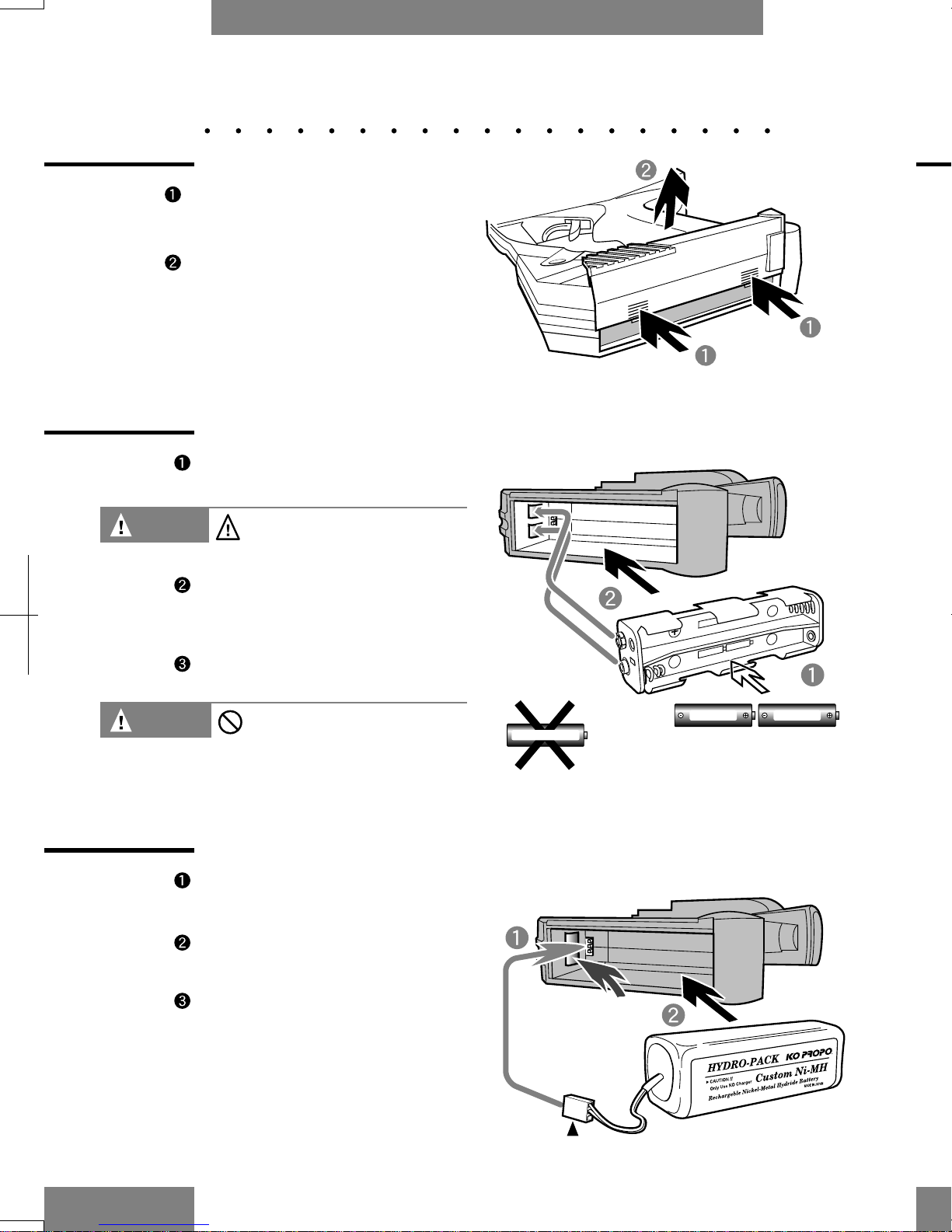
Da nge r Do not sho rt the ba tte ry te rmina ls.
*It is d a nge rous b e c a use it ma y b e the outb re a k o f fire o r e xp losio n .
Da nge r Ne ve r inc ine ra te the b a tte rie s.
*It is ve ry d a ng e rous b e c a use the y m a y e xplo de .
Da nge r Do not a p p ly b ig shoc ks to the ba tte rie s. *It m a y d a m a g e the b a tte ry
a nd re sult in short c irc uits a nd p o ssib ly a fire .
Do not d isma ntle o r m o d ify the b a tte ry.
*Dism a ntle the ba tte ry m a y c a use liq uid to le a k o ut a nd it is ve ry
d a ng e rous.
Da nge r
Do no t we t ba tte rie s a nd d o no t c ha rg e we t ba tte rie s.
Da nge r
Da nge r Be sure to use KO Propo c ha rg e r a nd use the c orre c t c ha rg ing
c urre nt.
*A vo id o ve r c ha rging the b a tte ry. O ve r c ha rging not o nly d a ma ge s
the ba tte ry, b ut c a n c a use e xc e ss he a t to b uild-up a nd p ossibly
c a use fire , re sulting in se rious a c c ide nts.
*Do not use the Hyd rop a c k with ra pid c ha rge rs from othe r
c om p a nie s, b e c a use the re is a po ssib ility tha t the a uto c ut-o ff
func tio n will fa il to o pe ra te .
In the e ve nt of liq uid le a king from b a tte ry, d o not a llow liquid to
touc h e ye s or skin. Burns a nd b lindne ss ma y oc c ur.A p p ly la rg e
a mo unts o f w a te r a nd c onta c t a do c to r imm e dia te ly fo r tre a tme nt.
Note s a fte r Driving (Sa iling)
Wa rning In the c a se o f e le c tric c a r use , b e sure to d isc o nne c t the nic a d
ba tte ry a fte rwa rd s.
*It ma y c a use fire o r the m ode l to run out o f c ontrol in c a se of switc h
be ing le ft on.
Wa rning Whe n storing the tra nsmitte r, b a tte rie s a nd mod e ls, b e sure to ke e p
the m o ut o f the re a c h of c hildre n.
*It ma y re sulting in d a ma ge b y c he mic a ls.
C a ution Be sure to d isc o nne c t the b a tte ry from the tra nsmitte r whe n not in
use for a longtim e .
*It ma y da ma g e the tra nsm itte r if you le a ve the ba tte ry in the
tra nsmitte r fo r a lo ng time .
C a ution Do not sto re the tra nsmitte r in the fo llowing p la c e s.
1. Extre me ly hot or c old p la c e s (+40C , -10C ).
2. Dire c t sunshine .
3. High hum id ity p la c e s.
4. Dusty p la c e s.
* If yo u store the unit und e r the se c irc umsta nc e s, it m a y re sult in
misop e ra tio nor d a m a g e to the unit.
C a ution
Da ng e r
Wa rning
Nic a d ba tte rie s a re re c y c la ble .
Ple a se support re c yc ling.
De sc ription Te rminology use d in Ra d io C ontrol M od e l usa g e .
38
AThe c ha rge r g e ts p ow e r supp lie d by A C m a ins.
A ud ible wa rning sound s from the tra nsmitte r.
A m e tho d o f e nc o d ing d a ta
by va rying the a mp litud e of a c o nsta nt c a rrie r.
Disp la y p la te whic h ind ic a te s c urre nt fre que nc y.
The numb e r a lloc a te d to e a c h se rvo,e c t.
C e ntra l proc e ssor unit.
The p a rt of a c omp ute r whic h c ontro ls a ll o the r p a rts.
De ta c ha b le e le c tric te rmina l unit.
Inte rc ha nge a ble ite m whic h c ha nge s the fre que nc y of the tra nsmitte r/re c e ive r.
The c ha rge r g e ts p ow e r supp lie d
by 12V b a tte rie s or c onsta nt p o we r supp ly unit.
The d e vic e whic h d isc ha rge s the re ma ining e ne rgy from nic a d b a tte rie s.
Ele c tric sp e e d c ontrolle r
whic h c ontro ls the RPM of the moto r for e le c tric p owe re d m o de ls.
The hig h c la ss se rvo using FET tra nsistor tha t inc re a se s the p o we r outp ut o f the unit.
A m e tho d o f e nc o d ing d a ta
by va rying the fre que nc y of a c onsta nt c a rrie r.
O ne of the wa ve ba nd s a llowe d for use in ra dio c ontrol mo d e ls.
Rubbe r ma te ria l to pre ve nt the vibra tion o f the se rvo.
A tta c h the m to the se rvo mo unts.
The sp e e d c ontrolle r tha t c ontrols the m oto r
with a fa st c yc le of fre que nc y. High e ffic ie nc y a nd sm o o th c ontro l.
A sse mb le d re c ha rge a b le nic ke l me ta l b a tte ry p a c k
with highe r c a p a c ity tha n a nic a d ba tte ry.
Liq uid c rysta l d isp la y.
Lig ht e m itting d iod e .Type o f d iod e tha t e m its light w he n c urre nt pa sse d throug h it.
Joint m e c ha nism be twe e n se rvo a nd the mod e l.
Pla te The p la te whe re the se rvo o r re c e ive r is insta lle d in the c ha ssis.
The d e vic e tha t c a n hold d a ta in ma c hine re a da b le fo rma t.
The p osition o f the se rvo whe n re le a sing the stic k or whe e l o f the tra nsmitte r.
A sse mb le d re c ha rge a b le nic ke l c a d mium b a tte ry
whic h is d iffe re nt fro m d ry b a tte ry c e lls.
The p he nome no n tha t is c a use d by the m o d e l
ove r re a c ting to the te e ring input.
Re sulting in sha rp e r turning a ng le tha n re q uire d .Stic k type of pa rts using in linka g e .
The c ha rge r whic h c ha rg e s the nic a d b a tte ry ve ry q uic kly.
The d e vic e tha t sta b ilise s the inp ut vo lta g e to the ne c e ssa ry le ve l.
The p a rt whic h c ha nge s the tra nsmitte d sig na ls into the rota tion m o ve m e nt.
The shoc k a bsorbing d e vic e tha t is insta lle d o r in p la c e o f se rvo horn.
The ha nd se t tha t tra nsmits sig na ls.
The m e c ha nism tha t c o ntrol the thro ttle pulling like a gun trigge r in
Turning a ngle of the se rvo ho rn.
O ne of the wa ve ba nd s a llowe d for use in ra dio c ontrol mo d e ls.
The p he nome no n tha t is c a use d by the m o d e l unde r re a c ting to the ste e ring
inp ut.Re sulting in w id e r turning a ng le tha n re q uire d .
The p a rt tha t c ontrols the ste e ring in the tra nsmitte r.
A C C ha rg e r
A la rm
A M (a m plitude mod ula tion)
Ba nd Pla te
C ha nne l
C om pute r(C PU)
C onne c tor
C ry sta ls
DC C ha rge r
Disc ha ge r
ESC
FET Se rvo
FM (fre que nc y mod ula tion)
40Mhz
G romme ts
High Fre que nc y ESC
Hydropa c k
LC D
LED
Linka ge
Me c ha nic a l
Me mory
Ne utra l
Nic a d Pa c k
O ve rste e r
Push Rod
Ra pid C ha rg e r
Re g ula tor
Se rvo
Se rvo Sa ve r Horn
Tra nsmitte r(TX )
Trigge r
Turning A ngle (Tra ve l)
27Mhz
Unde rste e r
Whe e l
B
C
D
E
F
G
H
L
M
N
O
P
R
S
T
U
W

Na m e s of Pa rts of the Tra nsmitte r
6
Fro nt sid e
Ba c k Sid e
Ste e ring trim (P10)
Pilo t La mp(LED)
G D-C Le ve r (P11)
LC D Displa y (P13)
Powe r Switc h
Ba tte ry
C o mpa rtme nt
Ro d A nte nna
C rysta l (P8)
G rip
G D-A Le ve r (P11)
C D-B Le ve r (P11)
Thro ttle Trim
C ha rging ja c k (P8)
Thro ttle Trig ge r
Note on Switc hing Powe r Switc h
off
A fte r the op e ra tio n o f func tion ke ys
a nd G D le ve r, d o no t switc h o ff for
a t le a st 1 se c o nd or e lse .Se tting
Ke y Pa ne l (P9)
Ste e ring W he e l
C H3
(P10)
Inde x
37
LC D Sc re e n
A
B
A UX.SEL
BRA K.Po s
C H4. Po s
G D.SELC T
MEM O RY ERRO R
MDL. SEL
SYSTEM M O DE
ST.RESPS
TH.RESPS
TRIM. Po s
(P13,26)
(P11,20)
(P28,36)
(P28)
(P9)
(P14)
(P13)
(P17,18)
(P21-24)
(P10)
A BS.C YC L
C H3. Pos
FUNC TIO N MO DE
Low BA TT
M DL NA M E
REV ERSE
ST. TRA V
TH.TRA V
TRA V . Po s
(P29)
(11,27)
(P13)
(P9)
(P29)
(P25)
(P15)
(P19,16)
(P11,16)
A BS
A la rm
A uto Disp la y
A C Ma ins c ha rge r
A M
(P38)
(P38)
Ba nd
Ba tte ry A la rm
Ba nd Pla te
(P38)
(P9)
(P38)
CC ha nne l (C H)
C ompute r (C PU)
C rysta l
(P38)
(P38)
(P38)
C ha rge r J a c k
C o nne c tor
(P6,8)
(P38)
D,E
FET Se rvo
Func tion Ke y
ESC
Disc ha rge rDC C ha rge r
Dire c t Se t
(P38)
(P12)
(P38)
(P38)
FFM
Func tion M od e
(P38)
(P9)
(P38)
(P13)
GG D Le ve r (P6)
H(P38) (P38)Hig h Fre q ue nc y ESC Hyd rop a c k
LLC D
LED
Linka ge
(P38)
(P38)
(P38)
(P8)
(P27)
LC D C o ntra st
LIN
MMe c ha nic a l Pla te
Ne utra l
N
OO ve rste e r
(P38)
(P38)
(P38)
Mo de l Se le c t
Nic a d p a c k
Pilo t La mp (LED)
(+) (-) Ke y
Ste e ring C urve
Ste e ring Tra ve l
Se rvo
Ste e ring Sp e e d
(P14)
(P38)
PPush Rod
Ra p id C ha rge r
Re g ula tor
Re ve rse
(P6,38)
(P9)
(P38)
(P38)
(P38)
(P38)
(P38)
(P38)
(P38)
(P25)
Re c e ive r (Rx)
Se le c t Ke y
Re se t
Se tting pa ne l
R
S
(P9)
Ste e ring Re sp onse
Thro ttle Re spo nse
Syste m M o d e
Trim
Thro ttle Punc h
Thro ttle Tra ve l
(P38)
(P15,16)
(P18)
(P9)
(P9)
(P13)
(P17)
(P17,18)
T
Tra nsmitte r (Tx)
27Mhz, 40Mhz
Trig ge r
Turning A ng le (Tra ve l) (P38)
(P38)
(P21)
(P19)
(P21)
Whe e l
Und e rste e r
(P38)
(P38)
U
W
(P24)
(P38)
(P10)

How to Use the Tra nsmitte r
How to Inse rt Dry C e lls (sold se pa ra te ly)
1. Inse rt e ig ht size A A b a tte rie s
into the b a tte ry bo x.。
Inse rt the b a tte ry b ox ma tc he d
with ba tte ry b ox te rm ina ls a nd
tra nsmitte r te rmina ls.
C lose the ba tte ry
c om pa rtme nt with c o ve r.
How to Inse rt a Nic a d Ba tte ry or Hy dropa c k (sold se pa ra te ly)
Plug in the c onne c tor of a
nic a d ba tte ry p a c k.
Inse rt nic a d ba tte ry or
hydrop a c k c orre c tly.
C lose the ba tte ry
c om pa rtme nt with c o ve r
Be sure not to c a tc h b a tte ry
le a d in b e twe e n c omp a rtme nt
a nd c o ve r.
7
Pre ss d own on the two
p oints ind ic a te d b y the a rro ws
Slid e the ba tte ry
c omp a rtme nt c o ve r off.
How to O pe n the Ba tte ry C ove r
+
‑
‑
C a ution Be ve ry c a re ful to loa d the
positive a nd ne g a tive te rmina l o f
e a c h b a tte ry p ro pe rly!
C a ution Do not use A A size nic a d
ba tte ry.It ma y c a use c o rrosion
insid e the tra nsmitte r with g a s
whe n c ha rg ing .
Te rmina ls
Fa c ing c orre c t d ire c tion
LC D Sc re e n Ta ble
36
LC D Sc re e n Na m e of Func tion
A BS C yc le P29
Exp la na tio n
C ha nging the p umping c yc le of A BS b ra ke .
M od e l Na m e P29
Inp ut na m e in M o d e l M e m ory.
Tra ve l Po sition P16
Disp la ys the c urre nt Ste e ring Tra ve l (turning a ngle ).
Bra ke Position P20
Disp la ys the c urre nt Bra ke Tra ve l (turning a ngle ).
Trim Position (ste e ring ) P10
Disp la ys the c urre nt positio n of Ste e ring Trim.
Trim Position (throttle ) P10
Disp la ys the c urre nt positio n of Throttle Trim.
C H3 Position P27
Disp la ys the c urre nt positio n of C H3.
C H4 Position P27
Disp la ys the c urre nt positio n of C H4.
Low Ba tte ry P9
Ba tte ry vo lta g e is d ro pp ing.
Re fe r to :
Me mory Error P9
Som e thing ha p pe ning o n the C PU m e mory d a ta .
1. 2V A A N ic d

How to Use the Tra nsm itte r
C ha rging
C o nne c t A C m a ins c ha rg e r
or DC 12v c ha rg e r (KO
Pro po p rod uc ts) into the Tx
c ha rg e ja c k a nd c ha rge .
C ha nging the C rysta ls
(c ha nging the fre que nc ie s)
Inse rt the c rysta l p rop e rly
a nd be c a re ful no t to be nd
the pins.
A djust LC D C ontra st
O ne of the c ha ra c te ristic s of a dot
ma trix
LC D is c ha nge of c ontra st de pe nding
of
the te m pe ra ture . A djust the c ontra st
so tha t the displa y is e a sy to se e . (4
le ve ls)
Powe r switc h on. (d ispla ye d initia l
sc re e n)
8
Wa rning In c a se o f nic a d ba tte rie s
be ing use d fo r tra nsmitte r
or re c e ive r, b e sure to
c ha rge prope rly.If the
ba tte rie s a re not fully
c ha rg e d ,the mo d e l m a y
run out o f c ontrol.
Wa rning Whe n c ha ng ing the c rysta ls,
be sure to use ge nuine FM-type
tra nsc e ive r c rysta ls from KO Propo.
C rysta ls from othe r ma nufa c ture rs
ma y o p e ra te a t slig htly d iffe re nt
fre que nc ie s, re sulting in loss o f
c ontrol.
C a ution Do no t c ha rge whe n using
d ry c e lls.If you c ha rg e d ry
c e lls, it c o uld c a use
d a m a g e the tra nsmitte r.
A C m a ins c ha rg e r
(sold se pa ra te ly)
C rysta l fo r Tra nsmitte r
The c ha rg ing tim e
fro m fla t c o nd itio n is
14-16 hrs fo r nic a d
a nd 25-35 hrs for
Hyd ro p a c k.
DC 12v Ra p id c ha rge r
(sold se pa ra te ly)
C ha rging c urre nt
le ss tha n 1A
Da rke rLighte r
Pre ss a nd hold
LC D Sc re e n Ta ble
35
LC D Sc re e n Na me of Func tio n
Throttle Tra ve l (F) P19,20
Exp la na tio n
A d justing turning a ng le o f fo rw a rd d ire c tion.
Throttle Tra ve l (B) P19,20
A d justing turning a ng le o f b ra ke d ire c tio n.
Throttle Re sponse (+) P21
Thro ttle Punc h.
The initia l e ffe c t of throttle re sp onse be c om e s "Q uic k"
Throttle Re sponse F (-) P22
Thro ttle Tra c tion C ontrol.
Sa ve the po we r on a c c e le ra tio n
whe n the trig ge r is p ulle d .
Throttle Re sponse B (+) P23
Bra ke Punc h.
The initia l e ffe c t of b ra ke re sp onse be c om e s "Q uic k"
Throttle Re sponse B (+) P24
A BS (A c tive Bra king Syste m )
The inte rmitte nt move m e nt will b e a utoma tic a lly a p p lie d
a nd pe rforming pump ing b ra ke e ffe c t.
Syste m M od e Sc re e n P13
Disp la ys whe n e nte ring in Syste m Mod e
Se rvo Re ve rse P25
De te rmine the d ire c tion of se rvo
A uxilia ry C ha nne l Se le c t P26
Se le c t the m ove m e nt of a uxilia ry c ha nne l.
G D Le ve r Se le c t P28
A ssig ning va rio us func tio ns to the G D le ve r.
Re fe r to :

How to Use the Tra nsmitte r
Wa rning displa y in the LC D
9
Ke y Pa ne l
Wa rning If (Low Ba tt) sign a ppe a rs
c o lle c t the m o d e l imm e d ia te ly.
*The ra d io signa ls w ill b e c o m e
we a ke r, whic h c o uld c a use a
lo ss o f c o ntrol.
Func tion Ke y
Ea c h LC D displa y (Func tio n)
c ha nge s in o rd e r
If the ba tte ry volta ge d rop s to
8.7V o r le ss whilst the tra nsmitte r
is in o pe ra tio n, (Low Ba tt) will b e
d ispla ye d on the LC D sc re e n. In
this e ve nt, re p la c e the b a tte rie s
Se le c t Ke y
C ha nging the LC D d ispla y
(Func tion) e xc e p t fo r fig ure
d a ta . (i.e . C H)
How to pre ss the ke y
Pre ss the mid d le of e a c h
ke ys with fing e r
Do not use sha rp ma te ria l, it m a y
d a m a g e the c o ve r.
+, - , Ke y
C ha nging the LC D d ispla y (Func tion) of figure d a ta . Pre ss both
ke ys a t the sa me time will d isp la y d e fa ult figure .
(e xc e p t fo r so me func tions)
Ba tte ry a la rm
Wa rning If (M e mo ry Error) a ppe a rs
ple a se a sk for re pa ir. It ma y
re sult in misope ra tion.
The LC D sc re e n shown a t le ft
a p pe a rs if some thing ha p pe ns
on the C PU a nd (M e mo ry Error)
will b e d isp la ye d with a la rm.
Me m ory Error
LC D Sc re e n Ta ble
34
LC D Sc re e n Na m e of Func tion
Initia l sc re e n P13
Exp la na tio n
Sc re e n d ispla y whe n the po we r is first turne d on.
Func tio n Mod e sc re e n P13
Disp la ys whe n e nte ring in the Func tion Mod e .
Ste e ring Tra ve l P15
A djusting ove ra ll ste e ring se rvo turning a ngle .
Ste e ring Tra ve l L P12,15
A djusting le ft ste e ring turning a ngle .
Ste e ring Tra ve l R P12,15
A djusting rig ht ste e ring turning a ngle .
Mod e l Se le c t P14
C ha ng ing the m od e l m e m o ry.
Ste e ring Re sponse P17
A djusting the ste e ring re sp onse c ha ra c te ristic s.
Ste e ring Re sponse (-) P18
Ste e ring Sp e e d.
Ste e ring c ha ra c te ristic s of the c a r b e c o me "mild".
Ste e ring Re sponse (+) P17
Ste e ring C urve .
Ste e ring c ha ra c te ristic s of the c a r b e c o me "Q uic k".
Re fe r to :

How to Use the Tra nsm itte r
How to Use Trim Le ve r (A djusting the ne utra l of se rvo e tc )
During the linka g e p roc e ss, a d just the trim c lose to 'o'
position.
10
Ste e ring Trim
Thro ttle Trim
Trim p osition
(Ste e ring)
Trim p osition
(Throttle )
Whe n the ste e ring whe e l a nd
thro ttle trigg e r a re b oth in the
ne utra l p ositio n b y moving trim
le ft o r rig ht (up or d o wn),yo u
a ble to a djust the ne utra l
po sitio n.
A t the sa me tim e the LC D displa y
a utom a tic a lly ind ic a te s trim
po sition sc re e n.
(A uto d isp la y func tion)
A fte r the o pe ra tio n, it will re ve rt b a c k to
pre vious sc re e n in a ppro x. 5 se c ond s.
( d oe s not a p ply w he n in Syste m M od e )
Se tting ra ng e is R/L 0-80, (F/B0-80).
Ma ke sure tha t the se tting do e s not lo c k
the linka g e a nd c a use e xc e ssive fo rc e
to be a p plie d to the se rvo.
(In the throttle trim , it d oe s not m ove a t
hig h e nd . O nly the m a ximum turning of
bra king will b e e ffe c tive b y trim
a d justm e nt)
Note s on Insta lling the Re c e ive r
33
Do not se c ure the re c e ive r on the c ha ssis or the
"m e c ha nic a l de c k". V ibra tions will c a use the re c e ive r to
misfunc tion a nd m a y e ve n c a use inte rna l da m a ge to the
re c e ive r.Eithe r use the bra c k e t (re c e ive r holde r) provide d
with the kit, or e lse c ushion the re c e ive r with a sponge like
Note s on Insta lling the Re c e ive r (G a soline -powe re d c a r)
Ple a se follow the instruc tion a s in the illustra tion be low
whe n you mount the a nte nna holde r to the m e ta l or
c a rbon c ha ssis.Whe n using on FRP or c a rbon hollow
a nte nna on a ra c ing c a r, e tc ., do not pa ss the a nte nna
wire through the pipe , a llow it to tra il a wa y loose ly outside .
Note s on A nte nna Insta lla tion
A d vic e
Bra c ke t
Sp ong e
Pia no wire Pipe Pip e
A lum inium ho ld e r A lum inium ho ld e r Pla stic ho ld e r
Me ta l, c a rbo n
(O K if FRP o r p la stic )
Me ta l, c a rbo n
(O K if FRP o r p la stic )
So ld e re d to
lug boa rd
Me ta l, c a rbo n
Do no t se c ure
a nte nna wire
to the p la te

Whe n mounting
the re c e ive r a nd
a nte nna on the
"up pe r d e c k",
position the m a s
fa r a wa y from the
nic a d b a tte rie s
a nd motor a s
possible .
Do not p osition the a nte nna
op e ning or the c rysta l ne a r
the nic a d b a tte rie s, mo to r, or
the c a rbon c ha ssis.
How to Use the Tra nsmitte r
G D le ve r A a nd B op e ra te s le ft
a nd rig ht.G D le ve r C op e ra te s
up a nd d own.
G D le ve r A will a d just the
ste e ring tra ve l (turning a ngle )
During this op e ra tion, LC D
d ispla y a uto ma tic a lly c ha ng e s
to the tra ve l p ositio n ( d oe s not
a p ply whe n in Syste m mo de ),
a nd re turn to the p re vious
sc re e n d ispla y a fte r a p prox.
5 se c o nd s.
G D le ve r B w ill a d just the b ra ke
tra ve l (bra ke turning a ng le )
During this op e ra tion, LC D
d ispla y a uto ma tic a lly c ha ng e s
to the b ra ke p osition (d oe s not
a p ply whe n in Syste m M od e ),
a nd re turn to the p re vious
sc re e n d ispla y a fte r a p prox 5
se c o nd s.
G D le ve r C will o pe ra te C H3
fe a ture .During this op e ra tion,
LC D d ispla y a uto ma tic a lly
c ha nge s to the C H3 positio n
(d oe s not a p ply whe n in Syste m
Mo de ), a nd re turn to the
pre vio us sc re e n d ispla y a fte r
a p porx. 5 se c ond s. Ple a se re fe r
to pa ge 27 for se tting up e a c h
po sitio n.
How to Use the G D Le ve r
11
You c a n c ha ng e e a c h le ve r's func tion. ( G D le ve r se le c t, P28)
GD lever B
GD lever C
GD lever A
GDA
GDB
GDC
Note s on Re c e ive r Usa ge
32
Mounting the Re c e ive r (Ele c tric - powe re d c a r)
The insta lla tion position should
be a s fa r a s possible from the
motor, ESC , nic a d ba tte rie s,
silic one wire s or othe r noise
sourc e s.
Espe c ia lly, do no t route the
silic one wire s ne x t to the
re c e ive r. (must not be ne a r to
the c ry sta l)
FET se rvo blue wire (7.2V wire )
a nd switc he s c a n a lso g e ne ra te
noise , position the m a s fa r a wa y
a s possible from the re c e ive r
Note s on Insta lling the Re c e ive r
Whe n fixing the re c e ive r in pla c e on the c ha ssis or on the
"m e c ha nic a l pla te ", use two pie c e s of doub le -side d ta pe , one on
top of the o the r, a s tha t the re c e ive r is c ushione d som e wha t.
A d vic e
A nte nna
Do not mount the
re c e ive r dire c tly o n
the c ha ssis or
"me c ha nic a l d e c k"
Use tw o la ye rs o f
d oub le -sid e d ta p e .
Do not p osition the
c rysta ls on the
bottom
A lw a ys p ositio n the
c rysta l on the top
Do not a llow the silic o n wire s to
c ro ss the a nte nna .
Do not route the wire s ne a r the
a nte nna .
The silic on wire p a sse s d ire c tly
ove r the re c e ive r.
Do not p o sition
the re c e ive r or
the a nte nna o n
top of the mo to r
or the nic a d
ba tte rie s.

to full fo rwa rd to full bra ke
How to Use the Tra nsmitte r
12
Sim ple Wa y to A djust the Turning A ng le of the Se rvo
(Dire c t Se t Func tion)
Turn the whe e l to the
ma xim um position of le ft or
right a nd yo u c a n a d just the
turning a ng le o f e a c h
d ire c tio n b y o pe ra ting the
ste e ring trim le ve r.
In a d d itio n to the trim se tting ,
the LC D d isp la y w ill
a utoma tic a lly c ha ng e to the
ste e ring tra ve l func tion
d ispla y sc re e n
(d oe s not a pp ly whe n in Syste m
Mod e ), a nd re turn to the pre vious
sc re e n d isp la y a fte r a pprox 5
se c o nd s.
This se tting c a n ra nge from 0-130.
Mo ve the trigg e r to the
ma ximum position forwa rd o r
ba c kwa rd a nd you c a n a d just
the throttle a ng le
by ope ra ting the thro ttle trim .
In a d d itio n to the trim se tting ,
the LC D d isp la y w ill
a utoma tic a lly c ha ng e s to the
thro ttle tra ve l func tion
fo rwa rd a nd bra ke (F.B)
d ispla y sc re e n. (d oe s not
a p ply whe n in Syste m Mod e )
a nd re turn to the pre vio us
sc re e n a fte r a p prox. 5
se c ond s.This se tting c a n the
ra ng e fro m 0-130
Whe n a d justing the turning a ng le by dire c t se t, re le a se the trim le ve r a nd
re turn to ne utra l po sitio n o f whe e l or trigg e r. If you re le a se the trim in
op po site d ire c tion, it ma y re sult in a n inc o rre c t trim se tting.
O p e ra te the trim le ve r
Turn
the ste e ring
whe e l
Pull the throttle trigg e r
O pe ra te the trim le ve r a nd this
se tting c a n ra nge from 0-130.
O pe ra te the trim le ve r a nd this
se tting c a n ra nge from 0-130
O pe ra te
the trim le ve r
Ste e ring
Throttle
t
o
t
h
e
r
i
g
h
t
t
o
t
h
e
l
e
f
t
ブ
レ
ー
キ
一
杯
に
押
す
Note s on Re c e ive r Usa ge
31
The Sourc e of Noise a nd Ele c trom a gne tic Induc tion
(Ele c tric -powe re d c a r)
Insta ll the a nte nna hold e r a s ne a r to the re c e ive r a s
possible .
The e a sie r it is for the a nte nna to pic k up noise ,the
Dista nc e Be twe e n the Re c e ive r a nd A nte nna Holde r
A ssum e tha t a ll a re a s whe re la rg e c urre nts a re flowing a re g e ne ra ting
noise !
Loc a te a nte nna wire s a nd re c e ive rs a s fa r a wa y from the motor, ESC ,
nic a d ba tte rie s,a nd silic one wire a s possible . Noise is a type of ra d io
wa ve , a nd the re fore is ra dia te d (tra ve l through the a ir) in the sa me
Me ta ls a nd c a rb o n c a n a lso c o nd uc t
noise . A s a re sult, you sho uld ne ve r
c lo se ly a tta c h the a nte nna wire to the
pla te a nd c a rbon c ha ssis.
Be c a use this is a lso
pa rt of the a nte nna ,
it is e a sie r to pic k up
ne a rby noise . A d vic e

A bout LC D Displa y
Initia l Sc re e n
Mode l Na me
None store d whe n
unit is re le a se d
C urre nt m od e l num be r
a mo ng the thre e d iffe re nt
se tting sto re d in the m e mory.
Ba tte ry volta ge
Mode l Numbe r (1-3)
The LC D Sc re e n use d on this tra nsm itte r is divide d into two
mode s (group) . Sy ste m Mode inc lude s func tion sc re e ns tha t a re
use d during linka ge a nd tha t a re not use d during norm a l
C a lling Up LC D Sc re e n/ LC D Ma p
This Sc re e n is Displa ye d W he n the Powe r is First Turne d on.
13
Ente r Func tion M od e b y p re ssing the
func tion ke y while in Initia l Sc re e n. The n
pre ssing the Func tion Ke y in re gula r
se que nc e will c a use sc re e n to c ha ng e
a c c ord ing ly.
Ente r Syste m Mod e b y p re ssing a nd hold
Se le c t Ke y a nd p re ssing the Func tio n Ke y.
The n p re ssing the Func tion Ke y in re gula r
se q ue nc e will c a use the sc re e n to c ha ng e
a c c o rd ing ly.
Initia l Sc re e n
Func tio n M o d e Syste m M o d e
Re ve rse (p 25)
M o d e l Na m e (p 29)
A BS C yc le (p 29)
A uxilia ry Se le c t (p 26)
G D Le ve r Se le c t (p28)
Mod e l Se le c t (p 14)
Ste e ring Tra ve l (p 15) Thro ttle Re sp onse (p21)
Throttle Tra ve l (p19)Ste e ring Re sp onse (p17)
Pre ss the Func tio n Ke ys
simulta ne o usly
C onne c ting the Re c e ive r
30
Wa rning Be c e rta in to use only KO Propo
ge nuine FM c rysta l se ts(tra nsm itte r
a nd re c e ive r). Ne ve r use c rysta ls
pro duc e d b y o the r c o mpa nie s
sinc e suc h c rysta ls ma y va ry in
fre que nc y, w hic h c o uld le a d to
misop e ra tion or o ut o f c ontrol
Wa rning Be sure to use gromm e ts a nd be
sure tha t the se rvo is not touc hing
a ny m e ta l p la te s d ire c tly. * The
vib ra tio ns m a y d a ma ge the se rvo
a nd the m o d e l m a y run o ut o f
c ontrol.
Wa rning Be sure to c onne c t a ll e q uipm e nt
c orre c tly.If c o nne c tions a re
lo ose ne d b y vibra tion,the mo de l
ma y run out of c o ntrol.
C a ution Be sure to use ge nuine KO Propo
pro duc ts e .g. tra nsmitte r,re c e ive r,
ESC a nd o the r o p tion pa rts. * We
c a nnot a ssum e a ny re sp o nsibility
fo r the use of othe r c o mp a nie s
pro d uc ts with this unit.
C onne c ting
the re c e ive r
For a n e le c tric -po we re d c a r ( FET se rvo + FET
For a ga soline -powe re d c a r (6V FET se rvos)
For a ga soline -po we re d c a r ( 7.2V FET
Wa rning Do not c ut o r b und le the a e ria l
wire w ith othe r c ord s. It m a y re sult
in d e c re a sing the se nsitivity o f the
re c e ive r a nd ma y re sult in the
m od e l running o ut o f c o ntrol.
C a ution Be c a re ful not to re ve rse the
pola rity of the tra nsmitte r a nd
the re c e ive r. Re ve rse pola rity
c ould da ma g e the units.
C rysta l
re pla c e me nt
A nte nna Le a d
Ste e ring Se rvo
7.2V FET Se rvo
Re c e ive r
5N600m A h
6V Nic d Ba tte ry
6N600m A h
7.2V N ic d Ba tte ry
Switc h Ha rne ss
Re c e ive r
Re c e ive r
Throttle Se rvo
Ste e ring Se rvo
Throttle Se rvo
7V Re gule tor
Switc h Ha rne ss
Ste e ring Se rvo
Ele c tric
Sp e e d C o ntro le r
BA TT
C H1
Switc h Ha rne ss
Ste e ring Se rvo
C H2
ESC o r Throttle Se rvo
Re turn to
the Initia l Sc re e n
I'msorry,
Iforgotit.
Plesegive
me grometts
~~~~~~!!
Whyd idyou
tookthis
scratc h?

The Expla na tion of Ea c h Func tion (Func tion Mode )
14
C ha nging the Mode l Me m ory (Mode l Se le c t)
This tra nsmitte r c a n store
a ll se ttings for up to
thre e c a rs. This func tion
is use d to switc h a mong
those se ttings.
Pre ss the Func tio n Ke y two
tim e s to switc h to M ode l
Me m ory sc re e n.
The m o d e l num be r c a n b e
c ha nge d by using the (+)
a nd (-) ke ys.
C a ution Be sure to use Mo d e l Se le c t a nd
G D Se le c t a fte r you fully
und e rsta nd the func tions.
*Inc o rre c t ope ra tion ma y c a use
c a r to run out of c o ntrol.
The Expla na tion of Ea c h Func tion (Syste m Mode )
29
C ha nging the Pum ping C y c le o f A BS Bra k e (A BS C y c le )
Pre ss a nd ho ld d o wn the
Se le c t Ke y a nd the n p re ss the
Func tio n Ke y to c ha nge to the
Syste m M od e sc re e n.
Pre ss the Func tion Ke y 4 time s
from the Syste m Mod e sc re e n
to c ha ng e to the A BS C yc le
sc re e n.
Use the (+) (-) ke ys to se le c t.
For the g a soline -p o we re d c a r
sho uld b e se t SLO W, a nd fo r
the e le c tric -p o we re d c a r
sho uld b e se t Q uic k.
For the ESC in the e le c tric -p owe re d c a r, it will be c ha nge d b y the bra king e ffe c t
of insta lle d sp e e d c o ntrolle r. Sugge st to try bo th SLO W a nd Q UIC K c yc le se ttings.
For the g a soline -p owe re d c a r, the e ffe c t of this func tion will be c ha nge d b y the
spe e d o f throttle se rvo . SLO W c yc le sho uld b e b e tte r.
Two diffe re nt pumping c yc le s (inte rva ls) of A BS Bra ke c a n be se t.
C ursor
Pre ss a nd ho ld d o wn the
Se le c t Ke y a nd the n p re ss
the Func tion Ke y to
c ha ng e to the Syste m
M o d e sc re e n.
Pre ss the Func tion Ke y five
tim e s from the Syste m
Mod e sc re e n to c ha nge to
the M o d e l N a m e sc re e n.
Use the Se le c t Ke y to m ove
the c ursor. A nd the (+) (-)
ke ys to se le c t the
c ha ra c te rs.
To Input, C ha nge a nd De le te the Na me s in the Mode l Me mory
(Mode l Na me )
For up to six le tte rs or symbols c a n be store d in e a c h
(a ) Pre ss a nd
ho ld d o wn
(b )
(a ) Pre ss a nd hold d own
(b )
Whichc ar
driving
today?
A d vic e
Let's tryit!!

Ne utra l
The Expla na tion of Ea c h Func tion (Func tion Mode )
A djusting the Turning A ngle of the Ste e ring Se rvo (Ste e ring Tra ve l).
C ha nge the LC D d ispla y from
the Initia l Sc re e n to the Func tion
Mod e . (re fe r to P13)
Turn the ste e ring whe e l fully to
the right a nd the LC D
a utoma tic a lly d ispla ys the rig ht
whe e l ste e ring turning a ngle .
A d just a ng le b y p re ssing the trim
le ve r.
Turn the ste e ring whe e l fully to
the le ft a nd the LC D
a utoma tic a lly d ispla ys the le ft
whe e l ste e ring turning a ngle .
A d just a ng le b y p re ssing the trim
le ve r.
□A djusting by Trim Le ve r
(Dire c t Se t Func tion)
Pre ssing the Func tion Ke y thre e
tim e s from the initia l sc re e n it
d ispla ys the Ste e ring Tra ve l sc re e n.
Turn the ste e ring whe e l a ll the w a y
to the rig ht the n a d just the right
sid e turning a ng le b y p re ssing the
(+) (-) ke ys. (This se tting the ra nge
from 0-130).
Turning the ste e ring whe e l a ll the
wa y to the le ft the n a djust the le ft
sid e turning a ng le b y p re ssing the
(+) (-) ke ys. (This se tting the ra nge
from 0-130)
Whe n the ste e ring whe e l is in
ne utra l p ositio n, yo u c a n a d just
turning a ngle of b oth le ft a nd rig ht
a t the sa m e time by pre ssing (+) (-
) ke ys.
□ C a lling up the Sc re e n a nd A djusting
Be sure to se t the Tra ve l Positio n o f G D Le ve r A a t a ma ximum va lue
be fo re a d justing the linka ge .
15
Use (+) (-) ke ys
A fte r turning the whe e l,
op e ra te the Trim Le ve r
Turn
the ste e ring
whe e l
O pe ra te the trim le ve r a nd this
se tting c a n ra nge fro m 0-130.
F
u
l
l
y
t
o
t
h
e
r
i
g
h
t
F
u
l
l
y
t
o
t
h
e
l
e
f
t
Turn
the ste e ring
whe e l
F
u
l
l
y
t
o
t
h
e
r
i
g
h
t
F
u
l
l
y
t
o
t
h
e
l
e
f
t
A uto m a tic a lly re turns
to the p re vious sc re e nif
no op e ra tio n a fte r
a p p rox. 5 se c o nd s. Le ve r (A ~C )
G D Le ve r A
Func tion (C H3 / C H4 / TRV / BRAKE)
G D Le ve r B
C ha nge the func tion
b y using (+) (-) ke ys.
The Expla na tion of Ea c h Func tion (Syste m Mode )
28
Pre ss a nd hold d own the Se le c t
Ke y a nd the n p re ss the
Func tion Ke y to c ha nge to the
Syste m M od e sc re e n.
Pre ss the Func tion Ke y thre e
tim e s from the Syste m M od e
sc re e n to c ha nge to the G D
Le ve r Se le c t sc re e n.
Use the Se le c t Ke y to se le c t the
c ontro l tha t a func tion is to be
a ssig ne d to G D le ve r A ~C . The n
use the (+) (-) ke ys to se le c t the
func tion to b e a ssig ne d .The
func tio n se tting c a n b e
re p e a te d so p le a se be c a re ful.
C H3.......... (C H3 O pe ra tion)
C H4.......... (C H4 O pe ra tion)
TRA V (Ste e ring Tra ve l p o sitio n)
...........(C urre nt ste e ring turning a ngle )
BRA KE (Bra ke p ositio n)
...........(C urre nt bra ke a mo unt)
C a ution Ple a se use M o de l Se le c t, G D Se le c t a fte r you fully und e rsta nd the
func tio ns. *Inc orre c t se tting c a n c a use lo ss of c ontro l.
A ssigning V a rious Func tions to the G D le ve r (G D Le ve r Se le c t)
A llows func tion to be a ssigne d to the G D le ve r
Switc h the G D le ve r (A ~C )
b y using the Se le c t Ke y
(a ) Pre ss a nd
ho ld d ow n
(b)
Le ve r (A ~C )

The Expla na tion of Ea c h Func tions (Func tion Mode )
16
A djusting the Turning A ngle of the Ste e ring Se rvo (Ste e ring Tra ve l)
□ A djust by G D Le ve r
Whe n se t to Tra ve l Positio n
by G D Le v e r A , the turning
a ng le c a n be a djuste d
a ssuming
the va lue displa y e d on the
sc re e n a s ma ximum va lue .
C ha nge the LC D d ispla y from
the initia l sc re e n to the
Func tio n M o d e .
O pe ra te the G D Le ve r A , LC D
will be a uto m a tic a lly d ispla ye d
a nd the turning a ng le in b o th
the le ft a nd right d ire c tio ns
c a n b e a d juste d
simulta ne o usly.
*The se tting ra ng e is 0 ~ The
C a ution A fte r the linka g e p roc e ss, ma ke
sure the se tting do e s not loc k the
linka g e a nd c a use e xc e ssive
fo rc e to be a p p lie d to the se rvo .
*Exc e ssive forc e to the se rvo will
re sult in d a m a g e a nd loss o f
c ontrol.
a . O p e ra te the G D Le ve r
c .The turning a ngle in bo th the le ft a nd rig ht d ire c tio ns
c a n be a djuste d simulta ne ously
Initia l Sc re e n
b. Displa ys a utoma tic a lly
The Expla na tion of Ea c h Func tion (Syste m Mode )
27
How to se t up the A uxilia ry C ha nne l Position (Turning a ngle )
By o pe ra ting the le ve r in
whic h a n a uxilia ry c ha nne l
ha s b e e n se t d ispla ys e a c h
po sitio n o n LC D.
Whilst the po sitio n is
d ispla ye d , use (+) (-) ke ys
to a d just. O pe ra te
the le ve r
V a lue of e a c h position
Using (+) (-) ke y to a d just e a c h Po sition
Position
A djust the e a c h position of the se rvo in the G D le ve r
se le c tions.
C ha ng e the LC D sc re e n to the initia l sc re e n of the Func tion
(Fo r e xa mp le ) 3P Position se tting by G D Le ve r
1P
2P
3P
O p e ra te the le ve r to
the d ire c tio n yo u w a nt a nd
the b e e p e r so und s w ill b e
c ha nge d to the se t turning
a ngle .
In the C a se of LINe a r Move m e nt.
O p e ra te
the le ve r
Using (+) (-) ke y to a d just e a c h e nd position
End Point
End Point
L
i
n
e
a
r
M
o
v
e
m
e
n
t
Position of End Point
If yo u a ssigne d
this func tio n to G D A .
Yo u c a n a d just the turning
a ng le in bo th the le ft
a nd right d ire c tio ns e a sie r
In the C a se of 1P Position ~ 4P Position

The Expla na tion of Ea c h Func tion
(Func tion Mode )
A djusting the Ste e ring Re sponse C ha ra c te ristic s
(Ste e ring Re sponse )
C a n be a djusta ble into two differe nt c ha ra c te ristic s.
17
This func tion is e ffe c tive for c a rs le ss se nsitive ne a r the ne utra l po sition.
A s sho wn in the g ra p h, c ha nge the a ng le so tha t the se rvo mo ve s
q uic kly in re sponse to the a ng le the ste e ring whe e l is turne d ,
Pre ss the Func tio n Ke y four tim e s from the initia l sc re e n, to c ha ng e
to the Ste e ring Re sponse sc re e n.
A djust the Ste e ring C urve (se tting ra ng e +1~+100) b y pre ssing
the (+) (-) ke ys. Po sitive va lue s yie ld q uic ke r re sponse .
□Ste e ring C urve
Le ft Rig htNe utra l
Whe e l a ngle
Ne utra l
Se rvo O pe ra tio n
Rig ht Le ft
The Expla na tion of Ea c h Func tion (Syste m Mode )
26
Pre ss a nd hold d own Se le c t
Ke y from the initia l sc re e n the n
pre ss the Func tion Ke y, it will
c ha ng e to the Syste m M od e .
Pre ss the Func tion ke y two
tim e s from the Syste m M od e
sc re e n to c ha nge to the
A uxilia ry C ha nne l sc re e n.
Use Se le c t Ke y to c ha nge the
c ha nne l (C H) a nd the
move me nt p a tte rn c a n b e se t
by (+) (-) ke ys.
1P Position move m e nt
Pe rfo rm s like a p ush button op e ra tion
Whe n the le ve r is re le a se d (P1). W he n the le ve r is
ope ra te d (P2).
It is use ful for EG Re mote C ontrol Unit.
2P Position move m e nt
Pe rfo rm s like a to g gle switc h.
(P1) a nd (P2) switc he s by le ve r op e ra tio n.
3P Position move m e nt
Pe rfo rm s like a thre e p ositio n switc h.
(P1), (P2) a nd (P3) switc he s b y le ve r ope ra tion.
It is use ful for EP tra ile r g e a r shift c ha ng e
4P Position move m e nt
By le ve r ope ra tion, it c a n be switc he d fo ur
positions
LIN move m e nt
By le ve r ope ra tion, it pe rforms a ma ximum of 240 ste p s
mo ve me nt.
It is use ful for the me c ha nism whic h re quire s the
Se le c t the Move me nt of A uxilia ry C ha nne l (C H3) (C H4).
(A ux ilia ry C H Se le c t)
The re a re five diffe re nt wa y to se le c t the a uxilia ry c ha nne l (C H3)
Move m e nt p a tte rn.C ha nne l
(C H)
(a ) Pre ss a nd ho ld d ow n
(b )
A d vic e
0 se tting
Ste e ring C urve
100 se tting
0 se tting
Ste e ring C urve
100 se tting

The Expla na tion of Ea c h Func tion (Func tion Mode )
A djusting the Ste e ring Re sponse C ha ra c te ristic s ( Ste e ring Re sponse )
18
This func tion lim its the ma ximum
turning spe e d of the ste e ring
se rvo.
If whe e l op e ra tion is slowe r tha n
the se t sp e e d, the o pe ra tio n o f the
se rvo is not limite d by the se tting .
Pre ss the Func tio n Ke y four tim e s
from the initia l sc re e n, to c ha ng e
to the Ste e ring Re sponse sc re e n.
Ne g a tive va lue s (-) yie ld slowe r
turning spe e d . The se tting ra nge is
(0~100), with a -100 se tting
a pp lying ma ximum limit.
□Ste e ring Spe e d
The se tting up of the c a r is of c o urse ve ry imp orta nt fo r turning the
c a r smo othly. Ho we ve r ro ug h ste e ring wo rk is just a re sult in loss o f
grip in the front tyre s. Using the Ste e ring Spe e d c o ntro ls the ro ug h
ste e ring work a nd re sults in mo re g rip. Just like a n e xp e rt d rive r you
a re a b le to drive in a c a lm a nd ste a d y wa y e ve n thoug h d riving
with roug h ste e ring work.
C ha nne l
(C H)
The Expla na tion of Ea c h Func tion (Syste m Mode )
25
Pre ss a nd hold d own
Se le c t Ke y fro m the
initia l sc re e n the n pre ss
the Func tion Ke y, it will
c ha nge to the Syste m
M o d e sc re e n.
Pre ss the Func tio n Ke y
onc e from the Syste m
Mo d e sc re e n to c ha ng e
to the Re ve rse sc re e n.
Use Se le c t Ke y to
c ha nge the c ha nne l
(C H) a nd the d ire c tio n
c a n b e se t by (+) (-)
ke ys.
De te rm ine the Dire c tion of Se rvo a nd ESC Move m e nt (Re ve rse )
Use this func tio n whe n the d ire c tion of se rvo a nd whe e l, trigg e r
op e ra tio n is in re ve rse . It will be a b le to c ha nge the d ire c tion o f
se rvo fo r Ste e ring (C H1) a nd Throttle (C H2).
C H3 a nd the a uxilia ry c ha nne l c a n se t the op e ra tion d ire c tio n
in the re ve rse wa y.
Use a uxilia ry C H p osition (p 27) if you wa nt to de te rmine the
d ire c tio n o f se rvo to the re ve rse .
(a ) Pre ss a nd
ho ld d o wn
Dire c tion
R
E
V
E
R
S
(b )
A d vic e

The Expla na tion of Ea c h Func tion (Func tion Mode )
19
Be fore the linka g e
a d justme nt,Se t the bra ke
po sition o f the G D Le ve r
B a t m a xim um va lue .
This func tion a llows you to a djust the
a m ount of se rvo move m e nt individua lly for
forwa rd a nd bra ke .The re a re thre e wa ys to
a djust.
A djusting the Throttle Se rvo Move me nt (Throttle Tra ve l)
Pull fully Push fully
Thro ttle trigg e r
O p e ra te the trim le ve r a nd this
se tting c a n ra ng e from 0-130.
(re ve rts b a c k to pre vious
sc re e n in a p prox. 5 se c ond s.)
O p e ra te the trim le ve r
ブ
レ
ー
キ
一
杯
に
押
す
□A djusting by Trim Le ve r (Dire c t Se t Func tion)
C a ll up the LC D displa y of initia l sc re e n or func tion mode sc re e n.
O p e ra te the throttle trim
le ve r whilst the trig ge r is
pushe d fully,the LC D
sc re e n c ha nge s to the
b ra ke d ire c tio n (B)
a utom a tic a lly the n c a n
b e a d juste d .
O p e ra ting the throttle
trim le ve r whilst the
trigg e r is p ulle d fully, the
LC D sc re e n c ha nge s to
the fo rw a rd d ire c tio n (F)
a utom a tic a lly the n c a n
b e a d juste d .
A djusting Fo rwa rd Dire c tio n ( F) .
A djusting Bra k e Dire c tion (B)
The Expla na tion of Ea c h Func tion (Func tion Mode )
24
Whe n more b ra ke p owe r is re quire d or whe n the c a r c a nnot b e se t up we ll, this is a n e xtre me ly
e ffe c tive fe a ture . Firstly using the Bra ke Tra ve l fe a ture , se t up so tha t ma ximum b ra king p owe r
c a n b e ga ine d without g e tting whe e l lo c k. It m a y re quire se ve ra l a tte m pts to find the po int a t
whic h m a xim um b ra king p owe r c a n be g a ine d witho ut whe e l lo c k.
A BS (A c tive Bra k ing Sy ste m)
Push fully.
The se tting ra nge is -1~-100
Turn o n a nd off whe n A BS is in op e ra tion
Use
(+) (-) ke ys
W he n A BS is in
op e ra tion a nd the
thro ttle trim is se t
towa rds the b ra ke
d ire c tio n a nd still m ore
the bra ke tra ve l is
se tting to a la rg e va lue ,
the re is a po ssibility tha t
A BS m ove me nt will b e
le ft o ut. If this ha p pe ns
be sure to se t the bra ke
trim ne a r to the 0 va lue .
Whilst in bra king ope ra tion,
a pply ing the inte rmitte nt
move me nt a utom a tic a lly
a nd pe rforming pumping
bra k e e ffe c t.
Pre ss the func tion ke y six time s
from the initia l sc re e n to c ha ng e
to the Throttle Re spo nse sc re e n.
LC D d isp la ys b ra ke d ire c tion (B)
whe n the trig ge r is pushe d fully.
Ne g a tive va lue (-) se tting a pplie s
A BS fe a ture .
A d just the a m o unt o f b ra ke by
c ha ng ing the va lue on the
sc re e n.The se tting c a n ra nge
from -1~-100.
The p ilo t la mp will turn on a nd
o ff whe n the A BS func tion is in
ope ra tion.
If the pump ing c yc le is too fa st or
too slow, the c yc le c a n b e
a d juste d in the ABS c yc le sc re e n
(p 29).
C a ution
A d vic e
Table of contents
Other Ko Propo Transmitter manuals