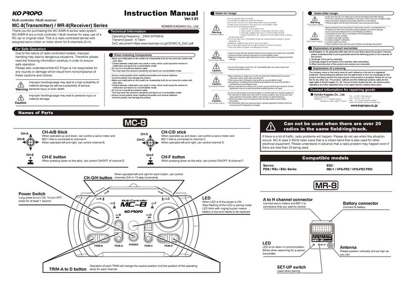
Ko Propo EX-10 EURUS User manual

Instructionmanual
All manuals and user guides at all-guides.com
all-guides.com

All manuals and user guides at all-guides.com

■Frontpage
■Contents
■Receiverinstallation
■Forsafeoperation
■Nameofparts
Adjustmentofsteeringtension
D.S.C.jack
MultiAccessPort
Headphonejack
Adjustmentofsteeringwheelandthrottletrigger
Steeringwheelextensionunit
Replacementofcolorpadandgrip(optionalavailable)
■Unitpreparation
Batteryinstallation
Attachmentandreplacementofmodule
Notesoninstallingreceiver(anti-noisemeasures)
InstallationandsettingofR/Cunits
■Procedurewhenrunning
■Setting
Functions
▶Startmenu
▶Modelmenu
Modelselect
Modelname
Modelcopy
Modelreset
Datapackformat
▶Steeringmenu
Steeringtrim
Steeringtravel
Steeringbalance
Steeringsubtrim
Steeringtrimrate
Steeringspeed
Steeringpunch
Steeringcurve
Steeringreverse
Dualrate
▶Throttlemenu
Throttletrim
Throttlehighpoint
Throttlebrake
Throttlesubtrim
Throttletrimrate
Throttlespeed
Throttlepunch
Throttlecurve
Throttlereverse
Neutralbrake
Autostart
ABS
Acceleration
Idling
▶Optionmenu
3CH・4CH
Response
Input
Setup
Volumeadjustment
Autorepeat
Poweralarm
Display
LED
Contrast
Backlight
Title
Intelligentrecognitionmodule
Buzzer
Customtone
Stopwatch
Downtimer
■Spec
■Backpage
1
3
4
5-6
7-9
7
8
8
8
9
9
9
10-13
10
11
11, 12
13
14
15-29
15
16
17
17
17
17
17
17
18-20
18
18
18
18
18
19
19
19
19
20
21-24
21
21
21
21
21
22
22
22
22
23
23
23
24
24
25-29
25
25
26
26
26
26
26
27
27
27
27
27
27
28
28
29
29
30
33
Page
Title
Page
Title
3
Contents
Contents
All manuals and user guides at all-guides.com

●For gas cars●For gas cars
●For electric cars
●For electric cars
●Running battery
●Receiver (KR-409S)
●Motor
●ESC
(Electric Speed Controller)
●Receiver battery
●Servos
●Servo
●Transmitter (EX-10 eurus)
●Module (RF-902S)
●Receiver (KR-409S)
When using units not included in the set, be sure to use only compatible products.
Please refer to our website for details (www.kopropo.co.jp)
Caution!
(CH1: steering servo, CH2: ESC)
(CH1: steering servo, CH2: throttle servo)
4
Receiver installation
All manuals and user guides at all-guides.com

With the nature of radio controlled model, improper usage may result in serious accidents. In order to avoid these
circumstances, please read following contents before use. We cannot be held responsible for problems encountered
when not complying with these cautions and notices.
●
Make sure metal parts do not come in direct contact to model (chassis/ship hull)
by vibration.
Noise of metal parts may result in malfunction of receiver, and the model may run
out of control.
●Do not cut nor bundle receiver antenna with other cables.
It may result in decreasing the sensitivity of receiver and may result in the model
running out of control.
●Note polarity when installing batteries to transmitter and receiver.
It may damage R/C units.
●Be sure to connect receiver, servo and switch connectors correctly.
If connections are loosened by vibration, the model may run out of control.
●Attach receiver using thick double-sided tape to avoid direct contact with other
parts.
Strong shock and vibration may result in the model running out of control.
●Operate servo to check that there are no unnecessary forces onto the push rod.
It may damage the servo or increase the consumption of batteries.
●Make sure to use rubber grommet to attach servo and be sure that the servo is
not touching mechanism plate directly.
The vibration may damage the servo and the model may run out of control.
●Use genuine KO transmitter, receiver, servo, speed controller and optional parts.
We cannot be held responsible for problems encountered when using with other
maker's products.
●Do not use in thunderstorms.
There is possibility of lightning striking the antenna.
●Do not use in the rain or in a location where water might get in.
The unit may become wet in and run out of control.
●Do not use in the following places.
1. Near to other radio control circuits (within 3km).
2. Near to people or on the street.
3. Near electric wires or communication facilities.
In the case of the model running out of control, dangerous situations will occur.
●Do not run the model when you experience difficulties in concentration through
tiredness, alcohol or medication.
The miss-judgment may result in accidents.
Warning! Failure to observe the matter discussed in such an item
poses a serious threat of death or severe injury.
Caution! Failure to observe the matter discussed in such an item
poses a possibility of injury or damage to the equipment or property.
Caution when installing units
Notes on driving
Read carefully and fully understand the following instructions for safety use.
Warning!
Enforcement matters
Warning!
Prohibited matters
Warning!
Prohibited matters
5
For safe operation
For safe operation
All manuals and user guides at all-guides.com

●Do not allow fuel or exhaust to touch plastic parts.
It may attack plastic.
●Make sure that model memory is matched to the model currently running.
Otherwise, it may cause car to run out of control.
●Make sure to stop engine (disconnect motor cables) before making function
change.
●Do not touch engine, motor or speed controller immediately after running.
They are hot and can cause burns.
●Always turn on the transmitter first, followed by the receiver. When turning off,
turn off the receiver first, followed by the transmitter.
If you don’t follow the order, receiver may get interference and run out of
control.
●Dismantling of transmitter is prohibited and it can be punished. Disassembly
and modification of all units may cause accidents such as a short circuit. Also,
repair service may not be accepted in this case.
●
Do not use in aircraft, hospital or near electrical equipment such as fire alarm or
medical equipment. It may cause malfunction and result in serious accidents.
Turn off the transmitter immediately if it effects on other wireless or electric
appliances.
●When using with electric powered R/C car, make sure to remove batteries after
running.
If the power turns on accidentally, it may cause the model to run out of control
or fire disaster.
●Keep transmitter, batteries and model out of reach of children.
Chemical material may cause personal injury.
●Remove batteries from transmitter when not in use for a long time.
If you leave batteries in the transmitter, leakage may damage transmitter.
●Avoid storing transmitter and receiver in the following places.
1. Extremely hot or cold places (+40 or -10).
2. Under direct sunlight.
3. High humidity places.
4. Vibration.
5. Dusty places.
If you store the unit under these circumstances, it may result in deformation or
damage to the unit.
Notes after driving
Warning!
Enforcement matters
Caution!
Enforcement matters
Caution!
Enforcement matters
Warning!
Enforcement matters
Warning!
Prohibited matters
Caution!
Prohibited matters
6
All manuals and user guides at all-guides.com
all-guides.com

Throttle trigger
Power switch
Back key
Power indicator
Enter key
ET3 lever
Jog dial
Plus key
LM2 LED indicator 2 LM3 LED indicator 3
LM1 LED indicator 1
ET4 lever
ET5 lever
BT1 button
Factory setting
ET1: Steering trim
ET2: Throttle trim
ET3: Throttle brake
ET4: Steering travel
ET5: CH3
BT1: Unallocated
BT2: Unallocated
Hook ET1 lever
Steering wheel
12x4 LCD
ET2 lever
BT2 button
Minus key
Tech tip
Insert hex wrench (1.5mm) as shown and rotate it to the right (clockwise)
for stronger tension. Rotate it to the left (counter-clockwise) for weaker
tension.
By changing spring damper in the steering wheel, steering tension can be
adjusted.
Adjustment of steering tension
Battery box (inside)
Hex wrench
7
Name of parts
Name of parts
Transmitter (front)
All manuals and user guides at all-guides.com

Headphone jack(refer to P8)
D.S.C. jack(refer to P8)
Multi Access Port(refer to P8)
Charging jack(refer to P10)
RF Module(refer to P11)
Battery channel
Receiver
Turn off transmitter and remove rubber cover from D.S.C. jack. Connect D.S.C. cable (transmitter will be turned on
automatically).
During headphone or earphone connected, beeps from transmitter are effective. Headphone jack is monaural output.
Use only a module included in this set or one that is
compatible with the set.
Connect servo with receiver and set up.
5.
Connect receiver with battery using the channel not employed (such as CH3).
4.
(For KR-409S receiver) Press both +/- keys to choose Digital mode (see P25).
(For PPM receivers) Choose response mode NORM, HSP or ADV (see P25).
2.
Disconnect battery from receiver first, and then detach D.S.C. cable from transmitter.
6.
Connect D.S.C. cable to battery channel in receiver.
3.
1.
Remove crystal from receiver before connecting.
Caution!
By connecting receiver and servo directly with transmitter using D.S.C. (Direct Servo Control), you can configure settings
without transmitting radio wave in pit area or near R/C circuit (D.S.C. cable (optional available) required).
A jack for headphone/earphone (Φ3.5mm / separately available).
Extra 10 model memories are available (refer to P17).
Connecting Data Pack (optional available) or ICS Communication Adaptor/ICS USB Adaptor (optional available) using Multi
Access Port will allow for more fine data management.
Data Pack (optional available)
Allows for fine data controlling using a PC.
D.S.C. jack
Multi Access Port
Headphone jack
ICS Communication Adapter/ICS USB Adapter (optional available)
8
Transmitter (rear)
All manuals and user guides at all-guides.com

Steering wheel spacer
Initial setting: Tip of screw's face is flush with the inside of the spacer.
Attach on transmitter (refer to manual included in set for installation).
The trigger may be loosened by temperature, strong shock or after long use.
To avoid the trigger loosened, gluing is also effective.
Reduces movable range of steering wheel.
Mounting angle of steering wheel can be adjusted.
Tech tip
1. Detach steering sponge from steering wheel.
2. Insert hex wrench (2mm) as shown. Tighten both right and
left screws to adjust movable range.
3. Re-attach steering sponge.
4. Adjust steering angle using volume adjustment (see P26)
to maintain maximum steering angle.
Tech tip
1. Loosen screws using hex wrench (1.5mm).
2. Freely adjust brake trigger.
3. Tighten screws to fix brake trigger.
Multi-angle 3D adjustable trigger
Steering wheel extension unit
Freely adjust brake and throttle trigger’s position and angle.
Color pad and grip are optional available.
Adjustment of steering wheel and throttle trigger
Replacement of color pad and grip (option)
Hex wrench (2mm)
Steering wheel
Spacer
Screw
Screw
Screw
Pad
Grip
Ball joint
Brake trigger
Throttle trigger
Steering wheel (under view)
Steering wheel (inside)
Detachment
Extend grip end outward (1) and pull out (2).
Pull out pad toward the arrowed direction (3),
then detach tab (4).
Attachment
A
ttach pad and grip in the reverse procedures of detachment.
A
ttach tab (4), then insert pad end (3).
A
ttach grip by inserting tabs (2) and insert grip end (1).
Tech tip
1. Loosen screws under steering wheel extension unit using
hex wrench (3mm) as shown.
2. Adjust mounting angle.
3. Tighten screws to fix.
9
All manuals and user guides at all-guides.com

Battery Pack (optional available)
Do not use high voltage dry batteries (such as Lithium) because
the voltage is too high and may damage the transmitter.
Note polarity and use fresh batteries. Depleted batteries
may deteriorate radio power and cause malfunction.
Transmitter (bottom)
Install R6/AA/UM3 batteries ×8 in the battery box. Note
contact points.
2.
Apply buffer sponge on battery box lid inside.
Connect battery cable and store it in transmitter.
A chargeable battery pack (optional available)
For AC100V charger, charge battery pack for 14-18 hours
after discharged.
Connect KO genuine AC100V charger or DC12V quick charger
with charging jack as shown.
Slide battery box lid, pressing triangle on
the lid.
1.
Battery box lid
Battery box
Contact
AC charger
Battery Pack
DC12V quick charger
R6/AA/UM3 battery ×8
Caution!
Never charge R6/AA/UM3 batteries through transmitter. It will
occur leakage or burst, leading to serious damage of
transmitter.
Caution!
Caution!
When discharging battery pack, always remove it from
transmitter (do not discharge using charging jack).
Caution!
Read carefully and fully understand instruction manual
included in battery pack.
Caution!
Be careful that charging current does not exceed 1A.
Caution!
Battery installation
Installation
Charging
Note polarity.
Not used.
Be sure not to miss polarity of battery pack.
Be sure to connect battery cable correctly when using battery pack
other than KO genuine products. Always refer to the illustration in
the manual before battery installation.
10
Unit preparation
Unit preparation
All manuals and user guides at all-guides.com

For frequency change (2.4GHz, 27MHz, 40MHz), replace module.
Refer to instruction manual included in module.
A
ttach module as shown. When detaching, press both side of tabs on
the module and pull out module.
Caution!
Attach retractable antenna (optional available) when using frequency
27MHz or 40MHz.
Caution!
Turn off transmitter before module replacement.
Caution!
Carbon chassis
Assume that all areas where large currents are flowing are
generating noise! Locate antenna cable and receiver as far
away from the motor, ESC, silicone cables as possible (material
such as metal or carbon chassis also conduct noise).
R/C model is controlled by radio wave. Therefore, anti-noise
measure is the most important factor. Take measures to ensure
optimum performance of your R/C model and driving technique.
Battery
Receiver
ESC Silicone cable
Motor
Keep antenna cable far away from noise source!
Be careful of noise!Be careful of noise!
Attachment and replacement of module
Notes on installing receiver (anti-noise measures)
RF Module
NOISE
NOISE
NOISE
NOISE
NOISE
NOISE
NOISE
NOISE
NOISE
NOISE
11
All manuals and user guides at all-guides.com
all-guides.com

When fixing the receiver to the chassis or on the mechanism
deck, use more than 2 layers of double-sided tape to avoid
direct contact with chassis. Chassis and mechanism deck
(especially carbon material) can also conduct noise. Making
space between receiver with them is recommend to ensure
protection against noise.
Raise antenna cable vertically and set as high as possible. Pass cable into antenna pipe to protect from damage. Make the
tip of antenna cable aligned with antenna pipe end. Installing antenna holder far away from receiver may deteriorate radio
sensitivity. Locate antenna holder as near to the receiver as possible. Make sure that the antenna cable does not come in
direct contact with chassis, mechanism plate or other noise sources. Make sure to use plastic antenna pipe and mount. Do
not use metal antenna mount as it easily conducts noise and may cause troubles.
Engine vibration may damage the receiver. Make sure to attach grommet
(receiver holder) to reduce vibration. Do not attach directly to chassis or
mechanism plate using double-sided tape. The installation position should
be as far as possible from heat from engine or exhaust.
Plastic
antenna pipe
Plastic
antenna pipe
Plastic holder
Grommet
Aluminum holder
Aluminum holder
Piano wire
Double sided tape
Antenna cable
Tip of antenna pipe
(Usable with FRP or plastic chassis)
Soldering lug plate
●Receiver installation on carbon chassis
●Antenna installation
●Attaching to a gas car
Note receiver’s LED position when installing.
Note receiver’ s LED position when installing.
Do not cut or bundle antenna cable.
(It may result in breaking of wire and
deteriorate performance.)
NOISE
NOISE
NOISE
NOISE
NOISE
NOISE
NOISE
NOISE
NOISE
NOISE
NOISE
NOISE
12
All manuals and user guides at all-guides.com

How to pair
Check operation by turning OFF the receiver, transmitter
and then turning ON the transmitter and receiver.
Check operation by turning OFF the receiver,
transmitter and then turning ON the transmitter
and receiver.
Try pairing later or in another location if someone is pairing
near by. WiFi and microwaves also affect pairing.
Before using a receiver for the first time, pairing is required.
If you several receivers for one transmitter, pair is also required for each receiver when used for the first time.
Read instruction manual included in servo and ESC carefully.
Adjust steering, throttle and brake (refer to P18-24).
4.
Set fail-safe function (see below).
5.
Register receiver to transmitter (pairing/see below).
3.
Install battery in transmitter and attach module (refer to P10-11). Then, install running battery
for an electric car or install receiver battery for a gas car.
2.
Install and connect receiver, servo and ESC (for electric car) to your R/C car.
Be careful and note the anti-noise measures (refer to P11).
1.
1Attach module (RF-902S) to transmitter and raise
antenna.
2Keep pressing set button of the module and turn
transmitter on (LED on module will light up).
3After approx. 3 seconds, LED will light off. Then release
set button (LED will be dim and ready for pairing).
4Move receiver antenna close to transmitter (approx. within 1m).
5Hold the set button of the receiver and turn the receiver power
ON by either connecting the battery cable or turning on the ESC.
6Release the set button and receiver's LED will be solid.
Turn off the receiver and transmitter to save the pairing.
Operation check
Turn on transmitter and check if LED on module lights up.
Then turn on receiver and check if receiver’s LED lights up.
Setting fail-safe function
For safety use, please set fail-safe function.
For gas car, reset fail-safe function if the brake linkage is changed.
If not reset, the former setting will be used and may not be correct.
1Turn on transmitter.
2Turn on receiver. Check if servo operates correctly.
3Keep throttle trigger in brake or neutral position.
4Hold the set button on the receiver for 3 seconds.
5After the receiver's LED indicator goes off, release
the set button.
Operation check
Turn on transmitter and receiver. Then turn off transmitter and
check if fail-safe function is effective.
If R/C model runs out of control (in case receiver loses radio wave from transmitter),
the fail-safe function will keep throttle (CH2) to brake or neutral position for safety use.
Installation and setting of R/C units
Pairing
completed!
Within 1m
Battery connector
Receiver’s LED
indicator lights up
For 3 seconds.
LED
lights off
LED
lights off
Neutral
Brake
Choose brake or
neutral and hold the
trigger position.
Hold the set
button of the
receiver.
Set up complete
and release set
button.
13
All manuals and user guides at all-guides.com

EX-10 eurus automatically finds unused frequency band after switching on. This function is called "carrier sense".
To perform carrier sense effectively, switch the transmitter on around the running area as close as possible.
Checking model: Watch and check model to be used.
2.
Power on: Note surroundings and switch transmitter on, then switch receiver on.
1.
Checking movements: Raise wheels from ground and operate transmitter to check movements.
Detail adjustment using steering/throttle trim lever should be done while running. Adjust steering
balance by performing figure-8.
3.
Power off: Turn OFF receiver, transmitter and remove car battery.
4.
Make sure to switch the transmitter on and off in an interval of at least 5 seconds.
Stand
Figure-8
Trim lever
14
Procedure when running
All manuals and user guides at all-guides.com

Modelselect
Modelmenu
Modelcopy
Modelreset
Datapackformat
Steeringtrim
Steeringtravel
Steeringbalance
Steeringsubtrim
Steeringtrimrate
Steeringspeed
Steeringpunch
Steeringcurve
Steeringreverse
Dualrate
Throttletrim
Throttlehighpoint
Throttlebrake
Throttlesubtrim
Throttletrimrate
Throttlespeed
Throttlepunch
Throttlecurve
Throttlereverse
Neutralbrake
Autostart
ABS
Acceleration
Idling
3CH・4CH
Response
Input
Setup
Volumeadjustment
Autorepeat
Poweralarm
Display
LED
Contrast
Backlight
Title
Intelligentrecognitionmodule
Buzzer
Customtone
Stopwatch
Downtimer
Functions
17
17
17
17
17
17
18-20
18
18
18
18
18
19
19
19
19
20
Modelmenu
Steeringmenu
Throttlemenu
Optionmenu
21-24
21
21
21
21
21
22
22
22
22
23
23
23
24
24
25-29
25
25
26
26
26
26
26
27
27
27
27
27
27
28
28
29
29
15
Setting
Setting
All manuals and user guides at all-guides.com

Enterkey[ ]
Backkey[ ]
(+)Pluskey[ ]
ⓐ:Currentmodelmemorysnumber
ⓑ:Currentmodelmemorysname
ⓒ:Voltage
ⓓ:Optionalfunction(refertoP27).
【Startmenu】
【Modelmenu】(P.17)
【Steeringmenu】(P.18〜20)
【Throttlemenu】(P.21〜24)
【Optionmenu】(P.25〜29)
PowerON!
※LOWBATTblinkedwhenunder9.0V.
BACKBACK
ENTERENTER
BACKBACK
ENTERENTER
BACKBACK
ENTERENTER
BACKBACK
ENTERENTER
BACKBACK
BACKBACK
BACKBACK
BACKBACK
01: 0000000
BATT 12.5v
EX-10 EURUS
ⓐⓑ
ⓒ
ⓓ
Modelcontrolfunctions.
Themodelindicatesaprogramwithproper
settingsforeachcondition.
Steeringcontrolfunctions.
Throttlecontrolfunctions.
Otheroptionalsettingfunctions.
▶Startmenu
Startmenuforeachfunctionsetting.
ENTERENTER
BACKBACK
Jogdial[ ]
(−)Minuskey[ ]
+
‒
01: 0000000
BATT 12.5v
MD ST TH >OP
>SELECT >
NAME >
COPY >
ModelMenu
>TRIM 0
TRAVEL 100
BALANCE >
ST: -……I……+
>TRIM 0
HPOINT F100
BRAKE B100
TH: -……I……+
>CH3 >
CH4 >
RSP NORMAL
OptionMenu
01: 0000000
BATT 12.5v
>MD
ST
TH
OP
01: 0000000
BATT 12.5v
MD >ST TH OP
01: 0000000
BATT 12.5v
MD ST >TH OP
Right
(clockwise)
Left
(counter-clockwise)
16
All manuals and user guides at all-guides.com
all-guides.com

Movecursorwith[ ],chooseletterwith[ ]
Completewith[ ](return)
>01
02 0000000
03
MD:COPY02→01
COMPLETE
MDL:RESET
>01 0000000
02
03
MDL:SELECT
000000
MDL:NAME
Copiescurrentmodelmemorytoselectedmodememory
[ ]or[ ]Completewith[ ](return)
ByemployingDataPack(optionalavailable),extra10modelmemoriesareavailableinadditiontoinner
40memories(modelmemorieswillbenumberedfrom41-50).
Selectwith[ ]or[ ]
Completewith[ ](return)
【Modelselect】
【Modelname】
【Modelcopy】
【Modelreset】
《ConnectingDataPack》
●ConnectDataPackwithMultiAccessPort(refertoP8).
●Besuretoattach/detachDataPackwhiletransmitterturnedoff.
●IftheDataPackisremovedwhilethetransmitteristurnedon,alarmsoundsandmodelmenuswitchestomodelselect.
Chooseinnermodelmemory(1-40)immediately.
※Modelnamescrollsrighttoleft.
※40modelmemoriescanberegistered
(whenusingDataPack:50memories).
BACKBACK
ENTERENTER
BACKBACK
BACKBACK
ENTERENTER
ENTERENTER
BACKBACK
ENTERENTER
ENTERENTER
BACKBACK
BACKBACK
BACKBACK
BACKBACK
BACKBACK
selectsthemodelmemory.
※[ ]cancelscursor,[ ]choosesletter.
Forcancellation,enter[ ]
ENTERENTER
editsthemodelmemorysname.
+ ‒
BACKBACK
※Pressboth[ ]forasecondtodelete.
Whencursoriscanceled,onlytheletterchosenwillbedeleted.
+ ‒
ENTERENTER
copiesamodelmemory.
+ ‒
※Modelmemoryisoverwrittenoncurrentmemory.
※AlwaysdefaultDataPackwhenusinganewDataPack.
defaultscurrentmodelmemory.
COMPLETEblinks,andthenreturnstomenu.
S
tartmenu(P.16)
▶Modelmenu
NAME >
COPY >
>RESET
>
ModelMenu
COMPLETE
MDL:DPFormat
【Datapackformat】
ENTERENTER
defaultsDataPack.
COMPLETEblinks,andthenreturnstomenu.
COPY >
>RESET
>
>D.P.Format
>
ModelMenu
>SELECT >
NAME >
COPY >
ModelMenu
SELECT >
>NAME >
COPY >
ModelMenu
NAME >
>COPY >
RESET >
ModelMenu
+ ‒
Modelcontrolfunctions.Themodelindicatesaprogramwithpropersettingsforeachcondition.
【NotesonusingDataPack(optionalavailable)】
Pressfor
asecond!
Pressfor
asecond!
17
All manuals and user guides at all-guides.com

Chooseleftorrightwith[ ],setwith[ ]
Setwith[ ]or[ ]
Completewith[ ](return)
【Steeringtrim】
【Steeringtravel】
【Steeringbalance】
【Steeringsubtrim】
ENTERENTER
ENTERENTER
ENTERENTER
ENTERENTER
ENTERENTER
BACKBACK
ENTERENTER
BACKBACK
BACKBACK
BACKBACK
BACKBACK
setsneutralposition(L50〜0〜R50)
setsleftandrightmovableangles
(0〜150)
Toresetvaluespressboth[ ]forasecond
+ ‒
Toresetvaluespressboth[ ]forasecond
+ ‒
Toresetvaluespressboth[ ]forasecond
+ ‒
Toresetvaluespressboth[ ]forasecond
+ ‒
Toresetvaluespressboth[ ]forasecond
+ ‒
Toresetvaluespressboth[ ]forasecond
+ ‒
※%hereindicatestheratioagainstmovableanglessetat
【Steeringtravel】.
setsleftandrightmaximummovableangles
>40〜100%
+ ‒
adjustsneutralpositionbyshiftingsteering
movablerange (L80〜0〜R80)
【Steeringtrimrate】
BACKBACK
changessensitivityofsteeringtrim
(1〜10)
NEXT▼
※Alsoreferto【Dualrate(P20)】
▶Steeringmenu
Steeringcontrolfunctions.
BALANCE >
>SUBTRIM 0
TRIMRATE 10
ST: -……I……+
>RIGHT 70%
LEFT 70%
ST:BALANCE
>TRIM 0
TRAVEL 100
BALANCE >
ST: -……I……+
TRIM 0
>TRAVEL 100
BALANCE >
ST: -……I……+
TRAVEL 100
>BALANCE >
SUBTRIM 0
ST: -……I……+
SUBTRIM 0
>TRIMRATE 10
SPEED 0
ST: -……I……+
+ ‒
Setwith[ ]or[ ]
Completewith[ ](return)
ENTERENTER
+ ‒
Setwith[ ]or[ ]
Completewith[ ](return)
ENTERENTER
+ ‒
Setwith[ ]or[ ]
Completewith[ ](return)
ENTERENTER
+ ‒
S
tartmenu(P.16)
18
All manuals and user guides at all-guides.com

Setwith[ ]or[ ]
Completewith[ ](return)
Setwith[ ]or[ ]
【Steeringspeed】
【Steeringpunch】
【Steeringcurve】
【Steeringreverse】
Thisfunctionallowsforsteeringspeedadjustmentinfirstpart
(Turn1/Return1)andlaterpart(Turn2/Return2)separately.
Timingofswitchingfirst/laterpartalsocanbeadjusted
(T.Pos/R.Pos).
100%:firstpart(slow)/laterpart(quick)
+100%:firstpart(quick)/laterpart(slow)
ENTERENTER
ENTERENTER
ENTERENTER
BACKBACK
ENTERENTER
BACKBACK
BACKBACK
BACKBACK
BACKBACK
setsservosworkingspeed.
>T.Pos / R.Pos:1〜100%
>Turn / Retun:1
(slow)
〜100
(quick)
setssteeringoutputfrom1%(rightandleft)
positionfromcenter (OFF〜80%)
ENTERENTER
setschangeratioofsteeringspeed
(100%〜OFF〜+100%)
changesthedirectionofservomovement
(OFF,ON)
Directionofsteeringandservoisoppositeduetoservo
installation.
※Settingeffectvariesaccordingto【Response(P25)】.
《Example》
CURVE OFF
>
REVERSE OFF
DualRate >
ST: -……I……+
>T.Pos 50%
Turn1 100
Turn2 100
R.Pos 50%
Return1 100
Return2 100
ST:SPEED
TRIMRATE 10
>SPEED >
PUNCH OFF
ST: -……I……+
SPEED >
>PUNCH OFF
CURVE OFF
ST: -……I……+
PUNCH OFF
>CURVE OFF
REVERSE OFF
ST: -……I……+
+ ‒
+ ‒
Choosewith[ ],setwith[ ]
+ ‒
NEXT▼
Setwith[ ]or[ ]
Completewith[ ](return)
ENTERENTER
+ ‒
Toresetvaluespressboth[ ]forasecond
+ ‒
Toresetvaluespressboth[ ]forasecond
+ ‒
Toresetvaluespressboth[ ]forasecond
+ ‒
19
All manuals and user guides at all-guides.com

Straight(smallerTRAVEL),lowspeedcorner(largerTRAVEL).
BACKBACK
ENTERENTER
BACKBACK
changessteeringtravelandbalancewhilerunning.
>KEY
(allocatesfunctionkey)
:OFF,ET1〜5,BT1,BT2
>BUTTON:
TGLE
(switches[dualrate]bypressingfunctionkey)
,
PUSH
([dualrate]iseffectiveduringholdingfunctionkey)
>TRAVEL:0〜150
>BLC.L
(forleftbalance)
:40〜100%
>BLC.R
(forrightbalance)
:40〜100%
《Example》
Choosewith[ ],setwith[ ]
※Alsoreferto【Steeringtravel(P18)】
and【Steeringbalance(P18)】.
+ ‒
【Dualrate】
※Pressorholdfunctionkeywhilerunning.
>KEY OFF
BUTTON
TGLE
TRAVEL 100
BLC.L 70%
BLC.R 70%
ST:DualRate
CURVE OFF
REVERSE OFF
>DualRate >
ST: -……I……+
Toresetvaluespressboth[ ]forasecond
+ ‒
20
All manuals and user guides at all-guides.com
Other manuals for EX-10 EURUS
3
Table of contents
Other Ko Propo Transmitter manuals
Popular Transmitter manuals by other brands

E+E Elektronik
E+E Elektronik EE650 user guide

Extron electronics
Extron electronics MTP T 15HD A user guide

Emerson
Emerson Rosemount 5400 Series quick start guide

Moseley
Moseley Starlink SL9003Q user manual

ABB
ABB PGS100 Operating instruction

Sentera Controls
Sentera Controls RSTHM-2 Mounting and operating instructions