Kobelt 7170 Series Instruction Manual

Kobelt Manufacturing Co. Ltd.
7170 Jog Lever
Owner’s Operation, Installation &
Maintenance Manual
February 2019

7170 Jog Lever Kobelt Manufacturing Co. Ltd.
Rev B MNL_7170 2 of 24
NOTES:
RECORD DATA BEFORE INSTALLATION FOR FUTURE REFERENCE
Model #:
Serial #:
Date of Purchase:
Date of Installation:

7170 Jog Lever Kobelt Manufacturing Co. Ltd.
Rev B MNL_7170 3 of 24
TABLE OF CONTENTS
1Introduction ............................................................................................................ 4
1.1 Contact .................................................................................................................... 4
1.2 Safety....................................................................................................................... 4
2Product Description ................................................................................................. 6
2.1 Technical Data ......................................................................................................... 6
3Installation .............................................................................................................. 7
3.1 Mechanical .............................................................................................................. 7
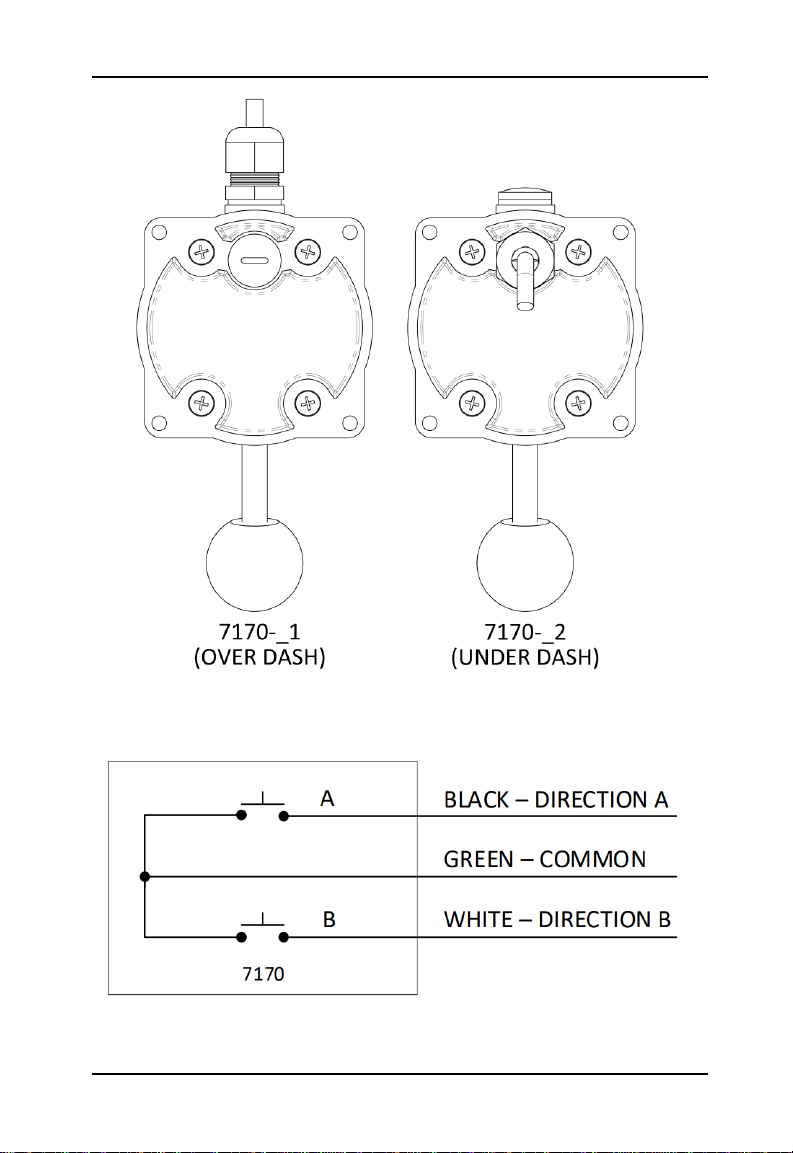
3.2 Electrical .................................................................................................................. 7
4Commissioning ...................................................................................................... 10
4.1 Electrical Check...................................................................................................... 10
4.2 Functional Test ...................................................................................................... 10
5Operation.............................................................................................................. 11
6Maintenance ......................................................................................................... 12
6.1 Preventative Maintenance..................................................................................... 12
6.2 Recommended Spare Parts and Kits ...................................................................... 12
7Troubleshooting .................................................................................................... 13
8Warranty............................................................................................................... 14
9Appendix A: Installation Dimensions...................................................................... 15
10 Appendix B: Parts List ............................................................................................ 16
11 Appendix C: Repair Kit Installation ......................................................................... 18
12 Appendix D: Spring Arm Replacement.................................................................... 20
13 Appendix E: Installation Cut-out Template ............................................................. 23

7170 Jog Lever Kobelt Manufacturing Co. Ltd.
Rev B MNL_7170 4 of 24
1INTRODUCTION
1.1 CONTACT
Kobelt Manufacturing Co. Ltd.
8238 129th Street
Surrey, British Columbia
Canada, V3W 0A6
Sales Tel:
Fax:
Email:
Website:
+1-604-572-3935
+1-604-590-8313
sales@kobelt.com
www.kobelt.com
This document is intended to clearly present comprehensive product data and provide
technical information to assist the end user in design applications. Kobelt reserves the right,
without notice, to change the design, or construction, of any products and to discontinue or
limit distribution of any products. Kobelt also reserves the right to change, or update, without
notice, any technical information contained within this document.
Kobelt recommends that customers visit our website to check for updates to this Manual.
Once a product has been selected for use, it should be tested by the user to ensure proper
function in all possible applications. For further instructions, please contact our distributors or
visit our website.
1.2 SAFETY
1.2.1 Safety Alerts
Throughout this manual, the following symbols, and their accompanying explanation, are
used to alert the user to special instructions concerning a service or operation that may be
hazardous if performed incorrectly or carelessly. The associated risk levels are stated below.
This symbol indicates an imminently hazardous situation which, if
not avoided, will result in death or serious injury.
This symbol indicates a potentially hazardous situation which, if not
avoided, could result in death or serious injury.
This symbol indicates a hazardous situation, which if not avoided,
could result in minor or moderate injury.
This symbol informs the reader of events not related to personal
injury but which there is a risk of damage to property or equipment.
This symbol informs the reader of safety-related instructions or
procedures.

7170 Jog Lever Kobelt Manufacturing Co. Ltd.
Rev B MNL_7170 5 of 24
1.2.2 Notice to Installer
Disregarding the following safety measures can result in an accident causing severe injury to
personnel and damage to material assets.
•Only use the product as directed in this manual.
•Never put the product into service if there is evidence of visible damage.
•Never put the product into service before fully completing installation and
commissioning.
•Do not carry out any modifications to the product.
•Only use authentic Kobelt spare parts.
•Observe all local regulations, directives and laws during the installation of this product.
•All installation, commissioning, and maintenance work must only be conducted by
qualified personnel. (For the purpose of this manual, qualified personnel are persons
who are familiar with the assembly, installation, commissioning, and operation of the
product and who have the qualifications necessary for their occupation.)
•Observe all specifications in this manual. If these guidelines are not followed and
damage occurs, the warranty will be voided.
1.2.3 Product Hazards
Disconnect Power: Turn off power at distribution panel before
beginning installation to protect installer from electrical hazards.
Voltage and Current Compatibility: Confirm that the power source
is compatible with the maximum voltage and current ratings of is
product variant. Failure to do so could result in damage or fire.

7170 Jog Lever Kobelt Manufacturing Co. Ltd.
Rev B MNL_7170 6 of 24
2PRODUCT DESCRIPTION
The Kobelt 7170 Jog Lever is used for input jog control to electronic and power hydraulic
steering systems. The operator can maneuver the vessel by simply jogging the lever port or
starboard to activate its internal micro switches. The Jog Lever can be used for steering
applications, other marine applications, or industrial installations.
The 7170 is designed for indoor and outdoor installation with a robust die cast bronze and
stainless steel construction to provide a long service life in a harsh marine environment.
The 7170 is available in a combination of black and chrome, all black, or all polished chrome
to suit your appearance preference and offers cable configurations either from the top or
bottom to accommodate a range of connection types and direction to match your
application.
2.1 TECHNICAL DATA
Table 1: 7170 Technical Data
MODEL
7170
KOBELT PART #
7170-A1
7170-A2
7170-B1
7170-B2
7170-C1
7171-C2
ELECTRICAL
CONTACTS
1 Form A, NO (Normally Open) (per direction)
MAXIMUM
VOLTAGE
250 VAC / 24 VDC
MAXIMUM
CURRENT
10 A (per switch contact)
HANDLE
TRAVEL
20° (per direction)
OPERATING
FORCE
1.5 lb·f [6.7 N]
PRODUCT
FINISH
Black Body and
Chrome Hub
All Black
All Chrome
GLAND EXIT
LOCATION
Top
Back
Top
Back
Top
Back
OPERATING
TEMPERATURE
-13°F … 158°F [-25°C … 70°C]
PRODUCT
WEIGHT
2.1 lbs [0.95kg]

7170 Jog Lever Kobelt Manufacturing Co. Ltd.
Rev B MNL_7170 7 of 24
3INSTALLATION
3.1 MECHANICAL
Ideally, the jog lever should be mounted in a central location at each station on-board the
vessel to control steering operation.
•Within 6 feet [1.8 m] of electrical junction box.
•Placed on horizontal or angled dash surface.
•Placed as to protect external electrical cable from damage.
The Jog Lever is equipped with (4) four clearance holes for #10 (M5) screws or bolts through
the top surface for direct mounting to the dash. Ensure the unit is securely fastened to a
suitable surface.
3.2 ELECTRICAL
The Jog Lever has a 6 foot [1.8 m] long 3C/18 cable for external connection. Connect it to an
electrical junction box and the electronic or power hydraulic steering system interface.
The product’s 3C/18 electrical cable contains the following wires and related functions:
Table 2: 7170 Wire Connections
7170
Wire #
Wire Name
Colour
Gauge
Function
1
SWA-NO
Black
18AWG
Connects to COM when Switch A is
activated.
2
SWB-NO
White
18AWG
Connects to COM when Switch B is
activated.
3
COM
Green
18AWG
COM connection.
The cable penetration location is shown in Figure 1 and the internal wire connections are
shown in Figure 2.

7170 Jog Lever Kobelt Manufacturing Co. Ltd.
Rev B MNL_7170 8 of 24
Figure 1: 7170 Cable Penetration Location
Figure 2: 7170 Internal Wiring Diagram

7170 Jog Lever Kobelt Manufacturing Co. Ltd.
Rev B MNL_7170 9 of 24
The operating direction of the Switches in relation to the Jog Lever handle is shown in Figure
3.
Figure 3: 7170 Switch Direction Diagram
Do not operate the Jog Lever if the internal spring has broken.
Unexpected operation could result.

7170 Jog Lever Kobelt Manufacturing Co. Ltd.
Rev B MNL_7170 10 of 24
4COMMISSIONING
4.1 ELECTRICAL CHECK
Ensure that the rear cover is installed and secured before powering
on the 7170.
•Confirm that the electrical connections to the 7170 have been made.
4.2 FUNCTIONAL TEST
The Functional Test should be carried out while the vessel is still at
dock and before it is taken out to sea after installation has been
completed.
A complete functional test should be performed on the system that the Jog Lever has been
installed within before entering operational use.

7170 Jog Lever Kobelt Manufacturing Co. Ltd.
Rev B MNL_7170 11 of 24
5OPERATION
The Kobelt 7170 Jog Lever contains a pair of contact switches, one for each direction of travel.
The Jog Lever also contains a centering spring that forces the lever back to centre when
pressure is not being applied by the operator.
The Jog Lever can be operated either Port or Starboard (Left or Right) to command motion in
the system it is controlling. The Jog Lever has three positions of operation as shown below.
Figure 4: 7170 Positions of Operation, LEFT - CENTRE –RIGHT

7170 Jog Lever Kobelt Manufacturing Co. Ltd.
Rev B MNL_7170 12 of 24
6MAINTENANCE
6.1 PREVENTATIVE MAINTENANCE
•Quarterly (4 times per year)
oVisually inspect wire and cable insulation for splits or damage.
oEnsure there is no visible corrosion on the unit.
•Every 2 years
oConfirm cable glands are secured to cables.
oReplace seals.
oReplace tension spring.
6.2 RECOMMENDED SPARE PARTS AND KITS
As a minimum Kobelt recommends that a spare 7170 Repair Kit be kept on-hand.
Depending on the date of purchase, a retro-fit kit may be required to mount the new more
robust spring found in the 7170 Repair Kit. When ordering a retro-fit kit, a repair kit should
also be ordered and installed together.
Table 3: Available Kits
AVAILABLE KITS
QTY
ITEM
KOBELT PART #
1
7170 REPAIR KIT
7170-RK
1
7170 RETRO-FIT KIT
7170-RF
When purchasing spare parts refer to Appendix B: Parts List at the back of this manual for
Kobelt component Part Numbers.
It is recommended that any required service work on a Kobelt unit
be performed by a factory authorized service representative. Please
contact the nearest Kobelt authorized distributor for assistance.

7170 Jog Lever Kobelt Manufacturing Co. Ltd.
Rev B MNL_7170 13 of 24
7TROUBLESHOOTING
If you encounter problems with the operation of your product, please refer to the trouble-
shooting suggestions before contacting Kobelt for assistance. If the steps below do not
resolve your issue, please reach out either Kobelt directly or our Dealers in your area.
Table 4: Common Solutions
Problem
(Issue encountered)
Cause
(What it means)
Corrective Action
(What to do)
Jog lever action is
reversed.
Wiring is backwards.
1. Swap the Switch A and Switch
B output wires to their
respective system connections.
Jog lever does not
move rudder at all.
Wiring is wrong.
1. Check wiring.
2. Refer to system design
drawing for proper wiring.
The rest of the system
isn’t hooked up correctly.
1. Check system wiring.
2. Confirm wiring to Jog Lever.
Broken switch or contact.
1. Use a multi-meter to monitor
the resistance of the wiring
between switch contacts.
2. Check for normal operation of
each switch by measuring the
connection while jogging the
lever.
3. Check both Switch A and
Switch B directions.
Replace any damaged
switches.

7170 Jog Lever Kobelt Manufacturing Co. Ltd.
Rev B MNL_7170 14 of 24
8WARRANTY
Kobelt Manufacturing Co. Ltd. (“Kobelt”) warrants the Products and Parts manufactured by
Kobelt to be free from defects in workmanship or material and that said products are
designed mechanically and functionally to perform to specifications.
This warranty is effective providing:
•The equipment is used within the intended operating conditions and in accordance with
Kobelt recommendations
•The equipment is installed according to equipment diagrams, specifications and
recommendations which Kobelt has provided
This warranty becomes invalid if the factory supplied serial number has been removed or
altered on the product. This warranty does not cover cosmetic damage or damage caused by
an act of God, accident, misuse, abuse, negligence or modification of any part of the product.
This warranty does not cover damage due to improper operation or maintenance, connection
to inappropriate equipment or attempted repair by anyone other than an authorized Kobelt
representative.
Upon identification of a potential issue or defect with a Kobelt Product or Part, the Warranty
Applicant (“Applicant”) must immediately contact Kobelt and describe the issue in writing, by
letter, fax, email or other electronic conveyance. Kobelt will then assess the cause of the
defect and determine warranty applicability and appropriate remediation.
If any part is found to be defective, Kobelt will replace said part FOB the Kobelt factory
provided that any such defective part is returned by the Buyer with freight and applicable
forwarding charges prepaid by the Buyer. Kobelt’s sole obligation to the Applicant will be to
repair or replace the defective part with same or similar product, to a maximum value of the
list price of the product or part. The Kobelt warranty does not cover labour charges, travel or
any other associated expenses.
All Products and Parts manufactured by Kobelt, are subject to a warranty against
manufacturer’s defects in materials or workmanship for a period of two (2) years from the
date of purchase.
Kobelt will be responsible for all Products or Parts sold by Kobelt but manufactured by 3rd
party manufacturing companies. However, these products and parts are subject to applicable
3rd party warranties and may not be the same as the Kobelt warranty.

7170 Jog Lever Kobelt Manufacturing Co. Ltd.
Rev B MNL_7170 15 of 24
9APPENDIX A: INSTALLATION DIMENSIONS
Figure 5: 7170 Installation Dimensions

7170 Jog Lever Kobelt Manufacturing Co. Ltd.
Rev B MNL_7170 16 of 24
10 APPENDIX B: PARTS LIST
Figure 6: 7170 Parts Diagram

7170 Jog Lever Kobelt Manufacturing Co. Ltd.
Rev B MNL_7170 17 of 24
Table 5: 7170 Parts List
Model Number:
7170
Part Number:
7170-A_
7170-B_
7170-C_
ITEM
QTY
DESCRIPTION
PART NUMBER
1
1
JOG LEVER HOUSING
7170-0001B
7170-0001B
7170-0001-
CHROME
2
1
JOG LEVER COVER
7170-0002B
7170-0002B
7170-0002-
CHROME
3
1
CAM
7170-0003
4
1
HUB
7170-0004-K
7170-0004B
7170-0004-K
5
1
HANDLE SHAFT
7170-0005
6
1
SHAFT
7170-0006
7
2
BRACKET, SPRING ARM
7170-0007
8
1
SPACER, JOG LEVER
7170-0009
9
1
BUSHING, SLEEVE, 7MM ID,
G300 PLASTIC
7170-0010
10
1
KNOB, BLACK
2030-0001
11
2
MICROSWITCH
6001-0104
12
1
CABLE GLAND, M16 X 1.5,
NYLON, BLACK
6001-0248
13
2
WASHER, M16, PE, CLEAR
6001-0248-W-M16
14
1
PLUG, CABLE GLAND, M16 X
1.5, BLACK
6001-0311
15
4
SCREW, PAN HD SLOTTED,
3-48 X 5/8, 18-8
1006-0310
16
4
SCREW, FLAT HD PHL, 10-24
X 5/8, 18-8
1009-0810
17
1
SPRING PIN, 3/16 X 7/8, SS
1024-0814
18
2
CABLE, 3C/18AWG, SVT,
300V, 105C
6014-0001
19
1
REPAIR KIT (SEALS AND
SPRING) FOR 7170
7170-RK

7170 Jog Lever Kobelt Manufacturing Co. Ltd.
Rev B MNL_7170 18 of 24
11 APPENDIX C: REPAIR KIT INSTALLATION
It is recommended that any required service work on a Kobelt unit
be performed by a factory authorized service representative. Please
contact the nearest Kobelt authorized distributor for assistance.
Steps for replacement of spring and seals:
1. Loosen cable gland.
2. Remove housing screws and cover plate.
3. Unthread handle shaft and remove shaft hub.
4. Remove spring arms (with spring and spring bushing attached).
5. Remove shaft assembly (be careful not to lose spacer).
6. Remove and replace small housing O-rings (4x). Refer to Figure 8.
7. Remove and replace large housing O-ring.
8. Remove and replace shaft O-ring.
9. Disconnect spring from spring arms.
10. Slide bushing onto new spring and re-attach to spring arms.
11. Reassemble unit as shown in Figure 7.
a. Use Loctite 242 or 243 on handle shaft threads and housing screw threads.
b. Ensure shaft has sufficient assembly grease (add more if necessary).
c. Refer to Figure 9 for spring arm orientation/order.

7170 Jog Lever Kobelt Manufacturing Co. Ltd.
Rev B MNL_7170 19 of 24
Figure 7: 7170 Parts Diagram for Maintenance
Figure 8: 7170 Maintenance Small Housing O-Rings Close-up

7170 Jog Lever Kobelt Manufacturing Co. Ltd.
Rev B MNL_7170 20 of 24
12 APPENDIX D: SPRING ARM REPLACEMENT
It is recommended that any required service work on a Kobelt unit
be performed by a factory authorized service representative. Please
contact the nearest Kobelt authorized distributor for assistance.
If your Jog Lever contains previous generation Spring Arms,
indicated by straight spring arms within the unit, this Retrofit Kit
should be applied to the unit during seal and tension spring
replacement at the next preventative maintenance cycle.
Steps for replacement of spring and seals:
1. Complete Steps 1-5 of outlined in Appendix C: Repair Kit Installation.
2. Discard old spring arms and spring.
3. Slide bushing onto new spring.
4. Attach spring (with bushing) to spring arms.
5. Slide spacer onto shaft assembly (before spring arms).
6. Reassemble unit as per Step 11 of Appendix C: Repair Kit Installation.
Figure 9: 7170 Spring Arm Order
This manual suits for next models
6
Table of contents
Other Kobelt Marine Equipment manuals
Popular Marine Equipment manuals by other brands

Pfannenberg
Pfannenberg BExCS110-05D-P instruction manual

CASSENS & PLATH
CASSENS & PLATH REFLECTA/1 Operation & installation

Apollo
Apollo Discovery 45681-700 installation guide

Humminbird
Humminbird ONIX operating guide

Federal Signal Corporation
Federal Signal Corporation G-SND-MV-D Installation and maintenance instructions

Satel
Satel ACSP SPP-401 quick start guide