KOCOM KLP-100 Instruction Manual

User’s Manual for Operation and Installation
Automatically opens common gate while communication with house
Connection with lobby phone up to 3 units
Keypad backlight function LED lamp
�
White LED function which can identify object at night : For Color Lobby phone
�
Infrared ray LED for night detection : For B/W Lobby phone
Camera angle control
�
For B/W Videophone : KLP 100, KLP P100, KLP 100RF
�
For Color Videophone : KLP C100, KLP C100RF
�
For Audio Doorphone : KDP 100
�
Door open by password or RF Card (option)
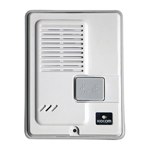
Lobby Phone
for Apartment Unit
PRODUCT
MODEL
DATE PURCHASED
WARRANTY PERIOD
AGENCY ADDRESS
KOCOM Warranties the original purchaser of this product
as follows.
1) This product is produced under strict quality control and inspection procedures.
2) If this product breaks down during proper use as a result of product defect, KOCOM
will repair it within one year from date of purchase free of charge.
3) The following cases will be subject to charge, even during warranty period:
a. Breakdown during transport, or through careless treatment, by consumer.
b. Breakdown cause by unauthorized repair, or system modification.
c. Breakdown caused by natural disaster or power disorder.
Warranty
Warranty Card
Lobby Phone 09.01
To receive after-Sale service, have the following ready
when you contact our branches
1. Name of the product
2. Model number of the product
3. The area of problem
4. Phone number and address at
which you can be contacted.
This manual is based on the date as shown in the right and specifications
are subject to change without notice for quality improvement.
B/W : KLP-100,
KLP-100RF
Color : KLP-C100,
KLP-C100RF B/W : KLP-P100
A dio : KDP-100

Product Specifications
Wiring Specifications
DC 17V 1V (standby: 2W, Operating: 9W),
Common Power Input
DC 12.8 V 1V
PROTOCOL DATA TX/RX Method
Hands Free Method (two way)
Calls/images maintains for 30 3 seconds after call
Communication with house maintains
for 3 minutes 5seconds
METAL ( Zn , Al ) / SILVER
255(W) X 120(H) X 20(D) mm
10C ~50C
At night, LED at Dial button is automatically turned on
120
0.1 Lux (When IR LED is turned on)
nput Power
Voltage of nternal Operation Power
Lobby Phone’s Data Protocol
Communication MethodAvailable
Time for Call/ mage
Exterior Material and Color
Dimensions
Guaranteed Operating Temperature
Automatic LED On/Off
Camera Angle
Minimum llumination
Lobby Phone
C MIC
Transmits input voices to receiver
Main Wiring : Voice 1 / Voice 2 / Data : (3 line) polar wiring, over TIV 0.8mm applicable
Power(17V/GND) (2 line) polar, over TIV 1.2mm applicable
For Video, coaxial cable is used : 5C 2V
KDP 100 is no necessary to connect Video line
Infrared Ray LED : B/W
White LED : Color
Detects and identifies objects at night
Camera Lens
Converts recorded images into signals
Speaker
Outputs voice signals
Set Button
Sets functions of device
Cancel Button
Used in canceling calls and
setting functions
Call Button
Used in call to house
Camera Angle Controller
Enables users to easily adjust
camera angle by manual
Video Amplifier Connector :
(KHU 102P): Composed of connector
for easier connection to Video amplifier (4Pin Wire)
(5V/Signal/ GND/Video)
Dial Button
Numbers are assigned
to call to each house
Reset Button
Resets and returns every
function to default value
Guardroom Call Button
Pressing “0”and “Call”
button in order, guardroom
(KIP 120) is called.
House Main Line Terminals
Adopt terminal type for easier
connection to main house line.
1: 17V
2: GND
3: Voice 1
4: Voice: 2
5: Video
6: Data
7: Door Lock
FND indicator
Characters are displayed
when setting or calling to house
Component’s Name
Precautions for Operation
Keep away from humidifier and stove.
High temperature and humidity may cause troubles.
Do not drop this device and avoid strong impact.
Keep away from devices generating strong magnetic filed (TV, Speaker, etc.)
(Images can be distorted or blurred as well as mechanical troubles may be caused.)
When cleaning, do not use wet hand, volatile benzene or paint thinner.
Keep image clear by cleaning camera window frequently with soft cloths.
As this device consists of electronic precision components, do not attempt to disassemble.
■KVS 104P (Relay) wiring (option)
90�(Pinhole lens)
Same as left
specifications
Same as left
specifications
KLP-100 / KLP-100RF KLP-P100 KDP-100
for connection
to Doorphone
Door Lock dry contact type
8. N.O. (Normal Open)
9. COMMON
10. N.C. (Normal Close)
Door open dry contact type
1. If the door opener is the type of ON dry
contact, please connect it to the Terminal
No.8 (N.O.) & 9 (COM.).
2. If the door opener is the type of OFF dry
contact, please connect it to the Terminal
No.9 (COM.) & 10 (N.C.)
3. Additional power supply is necessary in
this connection.
Same as left
specifications
KLP-C100
KLP-C100RF
97
0.1 Lux
(When WHITE
LED is turned on)
A. MAIN LINE (+18V, GND, VOICE1, VOICE2, DATA) OUTPUT
TO MONITOR IN HOUSE 1, 2.
B. MAIN LINE (+18V, GND, VOICE1, VOICE2, DATA) OUTPUT
TO MONITOR IN HOUSE 3, 4.
C. (VIDEO, GND) OUTPUT TO MONITOR IN HOUSE 1, 2.
D. (VIDEO, GND) OUTPUT TO MONITOR IN HOUSE 3, 4.
E. MAIN LINE (5 WIRE) INPUT FROM LOBBY PHONE
(COMMON GATE CAMERA) & (VIDEO, GND) INPUT
FROM KHU 102P.
F. MAIN LINE (5 WIRE) & (VIDEO, GND) OUTPUT TO
THE OTHER KVS 104P IN UPSTAIRS.
5 6
Operational Descriptions
■Functional Descriptions
▷
This product supports the following functions including call to and communication with house.
a. Call to and communication with house and guard b. Common gate open
c. Image transmission to house d. Lobby phone ID setting
e. RF card registration and deletion (option) f. Password registration per house
g. Lobby phone version check
These products are only compatible with KIV 102, D102, KIV 212, D212, KCV 802R, D802R, KVM 520/D520 monitor, KIP 603, KDP 603
doorphone or KIP 120 guard master. If it is used with other product(other company), it might be mal functioned.
▷
Call to house
In order to call from lobby to household, input house no. and press “call”button in order.
Pressing call button, call sound rings and house is called.
If the house responds to the call, communication is available for 3 minutes.
(Pressing door open button during the communication, opener installed common front door is opened.)
When communication is ended, device returns to standby mode.
※Pressing call button only on the lobby phone, the monitor, set as ID NO.1, is called automatically.
In case the house being called is on the line with extended lobby phone or guard, busy sounds(T,T,T,T) comes.
And it returns to stand by mode.
▷
Call from lobby phone to guardroom
Pressing “0”and call button on the lobby phone, guardroom is called, ID of Lobby emerges on the guard master.
Communication with guardroom is available for 3 minutes. When communication is ended, device returns to
standby mode.
▷
Private Password Setting
(Password change function is only available during the call with house.)
Pressing “# # 0 0 #” during communication with house, “_______” is displayed.
Input new password and press “#” button.
ex) In case registering ‘1111’ as password.
Only up to four ciphers are available for password.
▷
Door open using private password
In order to open the door by password from lobby, press ‘house number + # + password + #’, then the door is
automatically released.
ex ) In case opening common gate by password registered as ‘1111’.
External Wiring Diagram
Lobby phone can be extended up to 3 units.
House Video Output A
Video output port (A) to house, adopts
coaxial cable wiring. [coaxial cable 5C 2V]
Video
GND
House Video Output B
Video output port (B) to house, adopts
coaxial cable wiring.
[coaxial cable 5C 2V]
Extension Lobby phone Video Input
Video Input port from extended
Lobby phone. Coaxial cable wiring.
[coaxial cable 5C 2V]
Video Amplifier
Connection
Composes of connector for
easier connection to Lobby
phone. (1: 5V, 2: Signal,
3: GND, 4: Video)
※After cutting “4 Pin” connector,
long distance (upto 20m) connection
between Lobby phone and KHU 102P
can be made, using TIV 0.8mm cable.
■KHU 102P
Lobby Video Amplifier
Door lock dry contact type
1. If the door opener is the type of ON dry
contact, please connect it to the Terminal
No.8 (N.O.) & 9 (COM.).
2. If the door opener is the type of OFF dry
contact, please connect it to the Terminal
No.9 (COM.) & 10 (N.C.)
3. Additional power supply is necessary in
this connection.
KDP 100 wiring
No.5 (Video Out) terminal is not used.
Stand by Ho se N mber Call state Comm nication state Stand by
Stand by G ard master N mber Call state Comm nication state Stand by
Comm nication state Password inp t mode Hold New password # B tton
Stand by Ho se N mber # B tton password # B tton Releasing common gate
78

3 Lobbyphone Door Open Time Setting
From 1sec. Upto 8 sec. are available to set.
a) Press “SET” button again until “dOOR” sign emerges on display.
b) Press “CANCEL” button , then “02” (initial setting value) sign emerges on display.
c) Input new value from 1 to 8 and press “#” button to complete new door open time registration.
4 Bypass Call to Guardhouse Phone Setting.
This is the function to bypass the call from Lobby phone to Guardhouse phone (KIP 120) automatically,
when there is no answer till 30sec. from the monitor, while Lobby Phone calling.
“0”= no : no operation of bypass
“1”= yes : operation of bypass
a) Press “SET”button again until “dErO”sign emerges on display.
b) Press “CANCEL”button , then “no”(initial setting value) sign emerges on display.
c) Input new value between 0 and 1, then press “#”button to complete the bypass call function to Guardhouse phone
(KIP 120) or not.
If you do not use guardhouse phone KIP 120 in a system, the bypass call function to guardhouse phone setting
should be
““0””
= no in lobby phone.
5 Registration of Lobby Phone (KLP-100 series) RF- D Card (option)
Press “SET” button again until “RF.id.” sign emerges on display.
a) Press ‘Cancel’ button , then ‘In’ sign emerges and changes to ‘0’ sign at interval of a second.
At this time, contact the card to lens part. (1 time)
Registration tone sound is heard (twice). Indicator displays “1.”
b) Contact the card to lens part (once).
Registration tone sound is heard. Indicator displays “0002.”
c) Contact the card to lens part (once).
Registration tone sound is heard. Indicator displays “Oh .”
Registration of a card is completed. > Completion tone sound is heard (T.T.T.T).
In order to register a card, the card should be contacted to lens part total 3 times.
▷
Door open using common password.
Function is available only after setting up password.
To open common gate, press ‘# + common password + #’.
In case opening common gate by password registered as ‘1234’.
■Lobby Phone Setting
Press “SET”button.
Input 4 digit system password (default password:”9999”) and press “#”
1 Lobby phone System Password Setting.
Press ‘SET’ button again until “Lb.PS” sign emerges on display. After pressing ‘Cancel’ button ,
if you input new password and press ‘#’ button, then new password is registered.
ex) When making password ‘9999’ changed into ‘1111’.
Only up to four ciphers are available for password and the first digit should be over 1.(over 1000)
Be sure not to forget new password and not to expose it to the others.
2 Common Password Registration
a) Press “SET” button again until “GEPS” sign emerges on display.
b) Press “CANCEL” button , then “FFFF” (initial setting value) sign emerges on display.
c) Input new common password in 4digits and press “#” button to complete new common password
registration.
Only up to four ciphers are available for password and the first digit should be over 1.(over 1000)
Be sure not to forget new password and not to expose it to the others.
Operational Descriptions
SET
SET
SET
910
Stand by # b tton Hoid Common password # b tton Releasing common gate
B tton Hold Resistered password # b tton Setting mode
Lobbyphone password setting mode b tton Existing password Hold New password inp t b tton New password
b tton Initial setting val e Hold New Val e Inp t b tton
New Val e
Lobbyphone Door open
time setting mode
SET
SET
SET
Hold
New Password Inp t
b tton
New Password
b tton
Initial Val e
Common Password
Registaration mode
One Contact Two Contact Three Contact
RF-ID Card Registration mode b tton Inp t State Hold One Contact Two Contact Three Contact
b tton
Initial setting val e
Hold New Val e Inp t b tton
New Val e
Bypass call to G ard ho se
phone setting mode

6 Deletion of all RF cards.
Press “SET” button until “C.dEL.” sign emerges on display.
To delete, press “Cancel” button.
Tone sound of the deletion of all RF card IDs is heard for 60 seconds. When deletion is completed,
tone sound stops.
7 Lobby Phone D Setting
Press “SET” button until “Lbid” sign emerges on display.
Press “Cancel” button
Input new ID and press “#” button to finish ID registration.
Registration tone sound is heard.
In case of installing lobbyphone more than 1pc, each ID of lobbyphone should be resistered differently.
In order to use monitoring function of lobbyphone which has lobby mornitoring function,
the lobbyphone’s ID should be set as “1”.(This function is available only for KLP 100 series.)
Lobbyphone ID is available to set from 0 upto 9 number.
8 Protocol Setting
This function is to allow setting the house number DIP setting on monitor according to the building heights
or location.
Please be noted that the default value is Old protocol and there should be no mixed protocol in a system.
Mixed protocol in a system can make the malfunction of system.
“0” = no : Old protocol
House number DIP setting on monitor is possible from 1 to 63 number (901 to 963 or 3901 to 3963)
Over 64 to 100 number is not available to set
“1” = yes : New protocol
House number DIP setting on monitor is possible from 1 to 100 number
Upto 1599 number is available to set. Over 1599 number is not available.
a. Press “ SET” button again until “COIIII” sign emerges on display.
b. Press “CANCEL” button , then “no” (inital setting value) sign emerges on display.
9 Lobby Phone version checking
Press “RESET” button and version “5.02” is displayed.
Operational Descriptions
11 12
Lobbyphone ID setting mode b tton Existing ID Hold New ID Inp t b tton New ID
Protocol setting mode b tton Initial setting val e Hold New val e Inp t b tton New val e
Lobby phone setting Flow Chart
System Password
No
Yes
Lobby phone Password
setting mode Existing Password
Reset
Stand by
Hold
Hold
Hold
New Password Inp t
New Password Inp t
Common Password
Registaration mode
Lobby phone Door open
time setting mode
Bypass call to G ard ho se
phone setting mode
RF-ID Card Registration mode
Deletion of all RF Card mode
Lobby phone ID setting mode Initial setting ID
Initial setting Val e
Protocol setting mode
New ID Inp t New ID
Deleting card n mber
(60 sec.)
Initial Val e
Initial setting val e New Val e Inp t New Val e
New Password
New Password
b tton
b tton
b tton b tton
Hold
Initial setting val e New Val e Inp t New Val e
b tton
Hold
Hold
Hold
Hold New Val e Inp t New Val e
b tton
b tton
Over time
Inp t state One contact of RF card
Tone So nd (T.T.T.T)
Two contact of RF card
Three contact of RF card
b tton
b tton
b tton
b tton
b tton
b tton
b tton
SET
SET
RF card delete mode b tton
Deleting card n mber (60 sec.)
SET

Installation method
Dummy
Main Body
Dummy Screw 4x8mm(1ea)
Dummy Screw
4x50mm(4ea)
Rear Flush
Mounting Box
Specifications of Tenkey Button Type Products
Video phone connecting model
Audio Doorphone
connecting model
After placing adaptor 17V and video amplifier near to the Lobby phone.
Connect output of adaptor to the power terminal (+17V, GND [polarity]) of lobbyphone.
Connect4Pconnector from video amplifier to (KHU 102P)WAFERterminal of lobbyphone. [Polarity].
Reference before installation
Standard height for installation of Lobbyphone
From center of lens to bottom of
flush mounting box. [188mm]
Whole height of flush
mounting box. [220mm]
110mm 60mm
(Unit : mm)
Standard installation height of lobbyphone
is 1,400~1,450mm from floor to the bottom
of flush mounting box.
In case that the installation height of
lobbyphone is out of the range
(min.1,250mm~1,550mm), its hard to get
proper image, so be careful about the
installation height of lobbyphone.
Standard dimensions for installation of lobbyphone
500
780
(Unit : mm)
13 14

For Multi Apartment or Villa Use & its Connection using KVS 104P (Relay)
15 16

Video In / Out (Loop Out) Connection without KVS-104P (Relay)
17 18
Other manuals for KLP-100
1
This manual suits for next models
5
Table of contents
Other KOCOM Intercom System manuals

KOCOM
KOCOM KVM-340 User manual

KOCOM
KOCOM DS-4M User manual

KOCOM
KOCOM KDP-601A Instruction Manual

KOCOM
KOCOM KC-MC35 User manual

KOCOM
KOCOM KDP-602A Instruction Manual

KOCOM
KOCOM KCV-A374SD User manual

KOCOM
KOCOM KVM-524G Manual

KOCOM
KOCOM KC-MB20 User manual

KOCOM
KOCOM KIP-620ML User manual

KOCOM
KOCOM KVM-524RG Manual