Koganei ib-ZERO User manual

Catalog No.BK-V0018
http://www.koganei.co.jp
NEW OPTION!!NEW OPTION!!
End block with quick tting exhaust port
Intermediate piping block with
quick tting exhaust port
Piping block with
quick tting exhaust port
Intermediate piping block with quick tting exhaust port
1(P), 3(R) piping size
・φ10mm tube
・3/8 inch tube
1(P), 3(R) piping size
・φ10mm tube
・3/8 inch tube
Quick tting exhaust port typeQuick tting exhaust port type
Possible to exhaust with tube Possible to exhaust with tube
piping, from the 3(R) port of thepiping, from the 3(R) port of the
piping block.piping block.
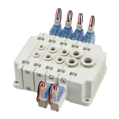
5-port manifold solenoid valve
PAT.PEND.
The rst in the world!
Integrally molded, all-plastic body!
35.335.3 mm
[1.3901.390 in]
1515
mm
[0.5910.591 in]
iB-ZERO Previous 180 series
All are integrated tting types (select from mm:φ4, φ6,φ8 / in: 5/32 , 1/4 , 5/16)
Perfect for cylinder controls from small diameter to about φ80 [3.150 in]
Simple Selection
Its simple conguration makes assembling the manifold a breeze.
Instant assembly →quick delivery
Easy assembly
⇦
* Valve width: 18 mm [0.709 in.]
Exhaust port
(Integrated mufer)
Thin and lightweight!
Nearly 40%
smaller
Nearly 57% less
mass than the previous
180 series manifold

12
Safety precautions
(iB-ZERO)
Before selecting and using the products, please read all safety precautions carefully to ensure proper product use.
The safety precautions described below are to help you use the product safely and correctly, and to prevent injury or damage to you,
other people, and assets.
Always adhere to the following safety regulations: ISO4414 (Pneumatic fluid power - General rules and safety requirements for systems
and their components) and JIS B 8370 (General rules relating to pneumatic systems).
Items are ranked as follows according to degree of potential danger or damage: “DANGER”, “WARNING”, “CAUTION”, and “ATTENTION”.
●
Before supplying air or electricity to the device and before starting
operation, always conduct a safety check of the area of machine oper-
ation.Unintentional supply of air or electricity could possibly result in
electric shock, or in injury caused by contact with moving parts.
●
Do not touch terminals, switches, or other parts, while power is turned
on.Doing so creates the risk of electric shock and malfunction.
●
Do not allow the product to be thrown into fire. Doing so creates the
risk of explosion and the release of toxic gases.
●
Do not sit on the product, place your foot on it, or place other objects
on it.Doing so creates the risk of injury due to tripping or the product
tipping over or dropping, resulting in product damage and abnormal,
erratic, or runaway operation.
●
When conducting any kind of operation for the product, such as
maintenance, piping connection and disconnection, inspection,
repair, or replacement, always turn off the air supply completely and
confirm that residual pressure inside the product or in piping
connected to the product is zero before proceeding. In particular, be
aware that residual air will still be in the air compressor or air storage
tank. The actuator could abruptly move if residual air pressure
remains inside the piping, causing injury.
●
Before commencing normal operation, confirm that the valve is in the
proper switching position,and only then commence the operation.
Failure to do so could lead to erroneous operation.
●
Before performing any kind of wiring work, be sure to turn off power.
Failure to do so creates the risk of electric shock.
●
Correctly apply the rated voltage to the solenoid. Applying the wrong
voltage will make it impossible to obtain the specified function, and
creates the risk of damage to and burnout of the product.
●
Do not allow lead wires and other cords to become damaged.
Allowing a cord to become cut, bent excessively, pulled, rolled up,
placed under heavy objects, or squeezed between two objects
creates the risk of current leaks or defective continuity that can lead
to fire, electric shock, or abnormal operation.
●
Do not connect or disconnect connectors while power is turned on.
Also, never apply unnecessary force to connectors. Doing so creates
the risk of personal injury, device damage, and electric shock due to
abnormal machine operation.
●
Always check the catalog and other reference materials for correct
product wiring and piping. Improper wiring and piping creates the risk
of damage to and abnormal operation of the actuator, etc.
●
In initial operations after the equipment has been idle for 48 hours or
more, or has been in storage, there is a possibility that contacting
parts may have become stuck, resulting in equipment operation
delays or in sudden movements. Before these initial operations,
always run a test to check that operating performance is normal.
●
When the device is not used for long periods (over 30 days), it is
possible that the contacting parts may have become stuck leading
to slow operation or sudden movements. Check for proper
operation a minimum of once every 30 days.
Always read these precautions carefully before use.
DANGER
Indicates situations that can be clearly predicted as dangerous.
Failure to avoid the situation creates the risk of death or serious injury.
It could also result in damage or destruction of assets.
WARNING
Indicates situations that, while not immediately dangerous, could become dangerous.
Failure to avoid the situation creates the risk of death or serious injury.
It could also result in damage or destruction of assets.
CAUTION
Indicates situations that, while not immediately dangerous, could become dangerous.
Failure to avoid the situation creates the risk of minor or semi-serious injury.
It could also result in damage or destruction of assets.
ATTENTION
While there is little chance of injury, this content refers to points that should be observed for appropriate
use of the product.
■This product was designed and manufactured for use in general industrial machinery.
■When selecting and handling equipment, the system designer or another person with sufficient knowledge and experience should
always read the safety precautions, catalog, instruction manual and other literature before commencing operation. Improper handling
is dangerous.
■After reading the catalog, instruction manual, etc., always keep them in a location where they are readily available for reference to
users of this product.
■If transferring or lending the product to another person, always attach the catalog, instruction manual, etc., to the product where they
are easily visible, to ensure that the new user can use the product safely and properly.
■The danger, warning and caution items listed under these safety precautions do not cover all possible contingencies. Read the
catalog and instruction manual carefully, and always keep safety first.
DANGER
●Do not use the product for the purposes listed below:
1. Medical equipment related to maintenance or management
of human lives or bodies.
2. Machines or equipment designed for the purpose of
moving or transporting people.
3. Critical safety components in mechanical devices.
This product has not been planned or designed for purposes
that require high levels of safety. Using the product in any of the
ways described above creates the risk of loss of human life.
●
Do not use the product in locations with or near dangerous
substances such as flammable or ignitable substances. This product
is not explosion-proof. Doing so creates the risk of ignition and fire.
●
When mounting the product and workpiece, always make sure they
are firmly supported and secured in place. Falling, dropping, or
abnormal operation of the product creates the risk of personal injury.
●
People using a pacemaker or other similar medical devices should
keep a distance of at least one meter away from the product. Getting
too close to the product creates the risk of malfunction of a
pacemaker due to the strong magnet built into the product.
●
Never attempt to modify the product. Abnormal operation can lead to injury, etc.
●
Never attempt inappropriate disassembly, assembly or repair of the
product relating to basic construction, or to its performance or to
functions. Doing so creates the risk of injury, electric shock, fire, etc.
●
Do not splash water on the product. Spraying it with water, washing it,
or using it under water could result in malfunction of the product
leading to injury, electric shock, fire, etc.
●
While the product is in operation, avoid touching it with your hands or
otherwise approaching too close. Also, do not attempt to make any
adjustments to internal or attached mechanisms, or to perform any
type of adjustment (manual override, connecting or disconnecting
cable connectors, adjusting pressure switches, disconnecting tubes
or sealed plugs, etc.) while the product is in operation.
Under such conditions, the actuator may move suddenly, creating
the risk of personal injury.
WARNING
●
Because Koganei products are designed for use under a wide variety
of conditions, decisions concerning conformance with a particular
system should be made upon the careful evaluation by the person in
charge of system design.Assurances concerning expected system
performance and safety are the responsibility of the designer who
decides system conformity. Be sure to use the latest catalogs and
technical materials to study and evaluate specification details, to
consider the possibility of machine breakdown, and to configure a
system that ensures fail-safe safety and reliability.
●
Do not use the product in excess of its specification ranges. Doing so
creates the risk of product breakdown, loss of function, or damage. It
could also drastically reduce operating life.

12
●
Always observe the following items.
1.
When using this product in pneumatic systems, always use
genuine Koganei parts or compatible parts (recommended parts).
When conducting maintenance and repairs, always use genuine
Koganei parts or equivalent parts (recommended parts).
Always observe the prescribed methods and procedures.
2.
Never attempt inappropriate disassembly or assembly of the
product relating to basic configurations, or its performance or
functions.
Koganei shall not be held responsible for any problems that occur as a
result of these items not being properly observed.
●
When considering the possibility of using this product in situations or
environments not specifically noted in the catalog or instruction
manual, or in applications where safety is an important requirement
such as in aircraft eguipment, combustion equipment, leisure
equipment, safety equipment, and other places where human life or
assets may be greatly affected, take adequate safety precautions
such as allowing plenty of margin for ratings and performance, or fail-
safe measures. Contact the sales department at Koganei regarding
use in such applications.
●
When handling the product, wear protective gloves, safety glasses,
safety shoes, and other protective clothing.
●
When the product can no longer be used, or is no longer necessary,
dispose of it appropriately, according to the “Law Regarding the
Disposal and Cleaning of Waste” or other local governmental rules
and regulations, as industrial waste.
●
Pneumatic equipment can exhibit degraded performance and function
over its operating life. Always conduct daily inspections of the
pneumatic equipment, and confirm that all requisite system functions
are satisfied, to prevent accidents from happening.
●
Air leakage of the solenoid valves cannot be cut to zero. Take volume and
holding time requirements into consideration when designing pressure
(including vacuum) retention in the pressure vessel, and other factors.
●
Air leakage of the solenoid valves cannot be cut to zero. Take volume and
holding time requirements into consideration when designing pressure
(including vacuum) retention in the pressure vessel, and other factors.
●
For double solenoid type (excluding the Tandem 3-port valve), do not
apply current through both solenoids simultaneously. It is impossible
in such a situation to maintain the correct valve position,and the
equipment may operate in an unintended direction, leading to the
possibility of equipment breakdown or personal injury.
●
For double solenoid types, due to the valve position when newly
purchased, connected equipment may operate in unintentional
directions,and may lead to damage of the machine, or personal
injury, so prepare countermeasures to avoid danger.
●
Do not locate the solenoid valve and the wiring that controls it near
power lines running a large current, powerful magnetic fields, or
where power surges occur. Doing so could cause erratic operation.
●
Solenoid valves generate surge voltage and electromagnetic waves
at the OFF operation, which can interfere with the operation of
nearby equipment. Use a surge protected solenoid or implement
appropriate surge and electromagnetic protection measures for the
electrical circuitry.
●
Do not use the product at the beach, in direct sunlight, near mercury
vapor lamps, or near equipment that generates ozone. Ozone causes
rubber components to deteriorate resulting in reduced performance,
or a limitation or stop of functions.(Excluding items with
measurements against ozone.)
●
Do not use any type of medium that is not specifically stipulated in the
specifications. Using a non-specified medium could lead to short term
loss of function, sudden degradation of performance, and a reduced
operating life.
●
When a solenoid valve is installed within the control panel and when
the energizing time is long, implement heat dissipation measures in
order to keep the temperature around the solenoid within
specifications. Also note that continuous energizing for long periods
will result in heat generation by the coil which can lead to deterioration
of solenoid valve performance and shortening of its service life, and
can adversely affect nearby equipment. Contact Koganei if you need
to continuously energize for long periods or if the energizing time in a
day needs to be longer than the deenergizing time.
●
After completing wiring work, check to make sure that all connections
are correct before turning on power.
●
When using the valve in a manifold, be aware when operating an air
cylinder, or performing air blowing operations, back pressure could cause
erratic operations of the cylinder or erroneous air delivery from the air blow
port. Caution is particularly needed when operating single acting cylinders,
or when operating a cylinder and blowing air from the same manifold.
●
Do not use the product in locations subject to direct sunlight
(ultraviolet radiation), high temperatures or high humidity, dust, salt,
or iron powder. Do not expose the product to fluids or an ambient
atmosphere that contains organic solvents, phosphate-based
hydraulic fluid, sulfur dioxide gas, chlorine gas, acids, etc. It could
lead to early shutdown of some functions, a sudden degradation of
performance, and a reduced operating life. For information about
materials, see Materials of major parts.
注 意
●
When mounting the product, leave room for adequate working space
around it. Failure to do so will make it more difficult to conduct daily
inspections or maintenance, which could eventually lead to system
shutdown or damage to the product.
●
Whenever transporting or installing a heavy product, use a lift or
supports to securely support it, and use several people to help lift it
and take other precautions to ensure personal safety.
●
Do not bring any magnetic media or memory media, or other similar
items within one meter of an energized solenoid valve. Doing so creates
the risk of damage to data on the magnetic media due to magnetism.
●
If leakage current is flowing in the control circuit, there is a possibility of
the product performing an unintended operation. Take measures against
current leaking in the control circuit, to ensure that the leakage current
value does not exceed the allowed range in the product specifications.
●Do not use a solenoid valve in locations subject to large electrical currents
or strong magnetic fields. Doing so could result in erratic operation.
●
Oil from a compressor (except from the oil free compressor) can
greatly reduce product performance and can even cause functional
stoppages. Be sure to install a mist filter before pneumatic equipment
to remove oil.
●
The properties of the lubrication oil can change when used in dry air
where dew point temperatures is lower than –20°C [–4°F]. It could
result in degraded performance or in functional shutdown.
●
While the product is in operation, avoid touching it with your hands or
otherwise approaching too close. Heat generated by the coil can
cause burn injury.
Safety precautions
(iB-ZERO)
ATTENTION
Warranty and General Disclaimer
1. Warranty Period
Koganei warrants this product for a period of no more
than 180 days from the date of delivery.
2. Scope of Warranty and General Disclaimer
(1) The Koganei product warranty covers individual
products. When a product purchased from Koganei or
from an authorized Koganei distributor malfunctions
during the warranty period in a way that is attributable to
Koganei's responsibility, Koganei will repair or replace
the product free of charge. Even if a product is still within
the warranty period, its durability is determined by its
operation cycles and other factors. Contact your nearest
Koganei sales office or the Koganei overseas
department for details.
(2) Koganei shall not be held responsible for any losses or
for any damage to other machinery caused by
breakdown, loss of function, or loss of performance of
Koganei products.
(3) Koganei shall not be held responsible for any losses
due to use or storage of the product in a way that is
outside of the product specifications prescribed in
Koganei catalogs and the instruction manual, and/or
due to actions that violate the mounting, installation,
adjustment, maintenance and other safety precautions.
(4) Koganei shall not be held responsible for any losses
caused by breakdown of the product due to factors
outside the responsibility of Koganei, including but not
limited to fire, natural disaster, the actions of third
parties, and intentional actions or errors by you.
Other precautions


34
●24 VDC
Internal circuit
1. Do not apply megger between the pins.
2. Malfunctions, such as the solenoid valve not returning to normal, may occur
if there is a leakage current within the circuit. Always use it at less than the
allowable leakage current shown in the solenoid specifications. If circuit
conditions, etc. cause the leakage current to exceed the maximum
allowable leakage current, consult us.
3. For the double solenoid configuration, avoid energizing both solenoids
simultaneously.
NOTE
NOTE
Solenoid with LED indicator and surge suppression
(-)
(+)
Lead wire
Red
Lead wire
Black
(Red)
Attaching and removing plug connector
Use fingers to insert the connector into the pin, push it in until the lever claw
latches onto the protruded section of the connector housing, and complete the
connection.
To remove the connector, squeeze the lever along with the connector, lift the
lever claw up from the protruded section of the connector housing, and pull it out.
Crimping of connecting lead wire and contact
To crimp lead wires into contacts, strip off 4 mm [0.16 in] of the insulation from
the end of the lead wire, insert it into the contact, and crimp it. Be sure at this
time to avoid catching the insulation on the exposed wire crimping section.
1.
Do not pull hard on the lead wire.
2.
Always use a dedicated tool for crimping of connecting lead wire and contact.
Contact: Model 702062-2M
Manufactured by Sumiko Tech, Inc.
Crimping tool: Model F1-702062
Manufactured by Sumiko Tech, Inc.
Protrusion
Pin
Housing
Lever
Connector
Indication of
polarity(DC)
Contact
Connector assembly
KSB0352Z
Hook Exposed wire
crimping section
Insulation crimp tab
Insulation (Maximum outer diameter: φ1.7 [0.067])
Lead wire
Equivalent to AWG#22〜#28
Exposed wire 4 mm [0.16 in]
Contact
NOTE
Attaching and removing contact and connector
Insert the contact with lead wire into a plug connector □hole until the
contact hook latches on and is secured to the plug connector. Confirm
that the lead wire cannot be easily pulled out.
To remove it, insert a tool with a fine tip (such as a small screwdriver)
into the rectangular hole on the side of the plug connector to push up
on the hook, and then pull out the lead wire.
1. Do not pull hard on the lead wire. It could result in defective contacts,
breaking wires, etc.
2. If the pin is bent, use a small screwdriver, etc. to gently straighten out the
pin, and then complete the connection to the plug connector.
KSB0353Z
To operate the manual override, press it all the way down.
For the single solenoid, the valve works the same as when in the energized
state as long as the manual override is pushed down, and returns to the rest
position upon release.
For the double solenoid, pressing the manual override on the 14 (SA) side
switches the 14 (SA) to the energized state, and the unit remains in that state
even after the manual override is released. To return it to the rest position,
operate the manual override on the 12 (SB) side. This is the same for the
solenoid 12 (SB).
PUSH
NOTE
1. The iB-ZERO series uses pilot type solenoid valves, so if you do not
supply air to the 1 (P) port, the main valve will not change, even if
you operate the manual override.
2. Do not attempt to operate the manual override with a pin or other
object having an extremely fine tip. It could result in damage to the
manual override.
Manual override
Identification of quick fitting size
Tube size unit Release ring color
mm size Ivory
in size Milk white
Handling Instructions and Precautions

34
1. While any mounting direction is allowed, be sure to avoid strong
shocks or vibrations applied directly to the body.
2. Avoid using in the locations and environment listed below, as it
could result in malfunction of the valve. If use in such conditions is
unavoidable, always provide a cover or other adequate protective
measures.
● Location directly exposed to water drops or oil drops
●
Environment where a valve body is subject to dew condensation
● Location directly exposed to machining chips, dust, etc
3. In piping connection with valves, flush the tube completely (by
blowing compressed air) before piping.
Intrusion of machining chips or sealing tape, rust, etc., generated
during plumbing could result in air leaks and other defective
operations.
4. Never use the valve with the 4(A) and 2(B) ports vented to the
atmosphere.
5. When mounting a valve inside a control panel, or when energizing
time is long, make adequate consideration for ventilation and other
heat dissipation measures.
6. When adding or subtracting units in the manifold, or replacing a
fitting block, be sure to tighten to within the specified tightening
torque range.
DIN rail mounting brackets
As shown in below images, rst make sure that the DIN rail mounting bracket is mounted on both sides of the manifold. Then
securely connect the hooks of both sides to the DIN rail from above, and x the position with DIN rail mounting screws.
When the DIN rail mounting bracket is selected, the maximum is number of valves is 16 stations.
DIN rail mounting screw
Fix with DIN rail mounting screw
Tightening torque 0.74 N [0.55 ft
・
lbf]
(Same for other side)
DIN rail mounting
bracket
Main unit mounting screw
Tightening torque 0.74 N
[0.55 ft
・
lbf]
Hooks (both sides)
NOTE
Mounting
1. Use air for the media. For the use of any other media, consult us.
2. Air used for the cylinder should be clean air that contains no
deteriorated compressor oil, etc. Install an air filter (filtration of 40
µm or less) near the valve to remove collected liquid or dust. In
addition, drain the air filter periodically.
3. When supply pressure is low, use piping for the 1(P) port with
sufficient tube size.
Media
Can be used without lubrication due to the factory lubricant (grease).
When the pneumatic products require lubrication, use Turbine Oil
Class 1 (ISO VG32) or the equivalent. In addition, cutting off oil feed
while an operation is in progress could lead to malfunction due to the
dissipation of the factory lubricant (grease). As a result, always keep
the oil feed running continuously. However, use caution since
excessive oil feed can also be a cause of malfunction. Avoid using
spindle oil or machine oil.
Lubrication
The product cannot be used when the media or ambient atmosphere
contains any of the substances listed below.
Organic solvents, phosphate ester type hydraulic oil, sulphur dioxide,
chlorine gas, or acids, etc.
Atmosphere
After wiring, check that there is no error in the wiring connections.
Wiring
Handling Instructions and Precautions
General precautions

56
How to assemble and replace valves
①
Remove the mounting screws (bracket attached) from the four places (when adding valves, the two places on the top and bottom of
where you are adding the valve) on the top and bottom of the valve to replace.
Refer to ③and ④when the customer is the one purchasing the end block and valves and assembling the manifold.
②
The valve and end block can be removed by opening them diagonally and pulling up.
③
Assemble while diagonally aligning the positions of the indents and protrusions of the new valve.
④
After attaching, x it with a mounting screws. (Recommended tightening torque: 0.49 N•m [0.36 ft•lbf])
Assemble or replace the valves while the manifold body is not xed.
Mounting screw
(bracket attached)
[Caution]
● Always turn off the power and the air supplies before starting work. Also, be sure to proceed after checking that all air from inside the manifold is
vented.
● The maximum number of units that can be connected in a series is 20, including intermediate piping blocks.
● Be careful that the gasket is not pinched or does not fall out.
● Before supplying air to the manifold, be sure to check that the connections that were made between each valve and end block are secure.
● We recommend adding intermediate piping blocks 「IBZR8Z-PJ(-PJ3/8)」 if needed, when there is a large number of valves or a large number
of valves simultaneously supplying air to the secondary side. Also, be careful of actuator malfunctions caused by the exhaust pressure.
Furthermore, both intermediate piping blocks 「IBZR8Z-PJ(-PJ3/8)」 and valves can be added using the same procedure.
● For muffler exhaust type, before use, confirm that there is no exhaust noise or increase in pressure in the control panel when it is sealed.
● Air leakage from valves is not zero. For questions regarding the allowable amount of leakage, contact our sales office.
[Warranty Period]
● The warranty period for this product is 12 months from the date of delivery. However, failure, loss of performance, or loss of function due to normal
degradation is outside the scope of warranty, even if it is within the warranty period.
Mounting
screw
(bracket
attached)
Air supply port
Air supply port
Exhaust port
(Integrated muffler)
Same on
other side
Right side
Gasket-side
Gasket
End block
Left side
Groove
Protrusion
Intermediate piping block
IBZR8Z-PJ
(Sold separately)
Open diagonally
Pull up
Close
Align the indents
and protrusions

56
iB-ZERO
Specifications
Notes 1: The effective cross section values are calculated values, and are not measured values.
2: Only when the intermediate piping block with quick tting exhaust port is selected.
3: The valve when air pressure is 0.5 MPa [73 psi].
Item Model IBZR8-4E1 IBZR8-4E2
Number of positions 2 positions
Number of ports 5
Valve function Single solenoid Double solenoid
Medium Air
Operation system Internal pilot type
Flow rate
characteristics
Sonic conductance C dm
3
/(s·bar)
J 4 2:0 . 8 、J 6 2:1. 6 、J 8 2:2
J 5 / 3 2 : 0 . 8 、J 1 / 4 :1 . 6 、J 5 / 1 6 :2
Effective cross section area [Cv value] Note 1 mm2[Cv]
J 4 2:4〔 0 . 2 2 〕、J 6 2:8〔 0 . 4 4〕、J 8 2:10〔 0 . 5 6 〕
J5/32:4〔0.22〕、J1/4:8〔0.44〕、J5/16:10〔0.56〕
Connection port size Supply port φ10 [0.394]Note 2, outlet port φ4 [0.157], φ6 [0.236], φ8 [0.315]
Supply port 3/8、
outlet port 5/32、1/4、5/16
Lubrication Not required
Operating pressure range MPa [psi] 0.2 to 0.7 [29 to 102]
Proof pressure MPa [psi] 1.05 [152]
Operating temperature range (atmospheric and medium) ℃ [℉]
5 to 50 [41 to 122]
Response time Note 3 on/off time ms 15/30 or less 30 or less
Maximum operating frequency Hz 5
Shock resistance m/s2[G] 294.2 [30]
Mounting direction Unrestricted
mm
in
mm
in
mm
in
Electrical Specifications
Rated voltage
Item 24 VDC
Applicable voltage range V 21.6 to 26.4 (24±10%)
Current (when rated voltage applied)
mA 23
Power consumption W 0.55
Allowable circuit leakage current
mA 1.0
Type of insulation B type
Insulation resistance Note MΩ 100 or over
Color of LED indicator Red
Surge protection (standard equipment)
Flywheel diode
Note: Value at 500 VDC Megger
Remark: Specication values are based on Koganei test standards.
Mass
Model Mass
IBZR8-4E1
J42: 59 [2.08], J62: 60 [2.12], J82: 63 [2.22]
J5/32
:5 9 [2.08]、
J1/4
:6 0 [2.12]、
J5/16
:6 3 [2.22]
IBZR8-4E2
J42: 75 [2.65], J62: 75 [2.65], J82: 78 [2.75]
J5/32
:7 5 [2.65]、
J1/4
:7 5 [2.65]、
J5/16
:7 8 [2.75]
IBZR8Z-E (end block) 81 [2.86]
IBZR8Z-E3/8 81 [2.86]
IBZR8Z-PJ 50 [1.76]
IBZR8Z-PJ3/8 50 [1.76]
IBZR8Z-EJ 84 [2.96]
IBZR8Z-E3/8J 84 [2.96]
IBZR8Z-PJJ 53 [1.87]
IBZR8Z-PJ3/8J 53 [1.87]
g [oz]
mm
in
mm
in

78
Note 1: Note1: The maximum number of valves is 20 stations. When the DIN rail mounting bracket is selected, the maximum is 16 stations.
2: After doing connections, before supplying air to the manifold, be sure to check that the connections that were made between each valve and end block are secure.
3: Please separately prepare the DIN rail. When -NS is selected for the maniflod format, the DIN rail mounting brackets will be attached parts.
4: Valve positions are counted from the left side of the manifold.
5: Common connector assemblies are available for common wiring connections. For details, see page ③.
6:
When connecting common wires between double solenoid valves on the 12 (SB) side, connections are possible between double solenoid valves if 1single solenoid valve is mounted between them, or even if
1 intermediate piping block is mounted between them. However, connections cannot be done if there are two or more, due to the relative length of the branch wires for common connections.
7: For questions regarding support for 5-V, 6-V, and 12-V DC products, contact our sales office.
8: (mm) fitting and (in.) fitting valves cannot be mixed in the same manifold.
Order codes
● Single valve unit (The single valve unit cannot be used alone.)
■Valve specifications ■
Specifications for fittings of pipe ports
■Wiring specification
-PL1-PL
-PLN
Note 1: Common connector assembly EAZ-PB is attached.
2: Common connector assembly EAZ-PB1 is attached.
3: Common connector assembly EAZ-PB3 is attached.
Remarks: The gasket is installed in the valve body. Two mounting screws (bracket attached) are provided with the valve body.
※For questions regarding support for 5-V, 6-V, and 12-V DC products, contact our sales office.
IBZR8 -4E1
-4E2 24 VDC
※
Model Valve specifications
Specifications for fittings of pipe ports
Wiring specification Voltage
-4E1: 5-port, 2-position single solenoid
-4E2: 5-port, 2-position double solenoid
Single solenoid Double solenoid
4 (A)
2 (B)
12 (SB)
14 (SA)
4 (A)
2 (B)
14 (SA)
3 (R2)
5 (R1)
1 (P)
3 (R2)
5 (R1)
1 (P)
L type plug connector
Lead wire 300 mm [11.8 in]
L type plug connector
Lead wire 1000 mm [39 in]
L type plug connector
No connector
-J42:
quick fitting for φ4 [0.157] tubes
-J62:
quick fitting for φ6 [0.236] tubes
-J82:
quick fitting for φ8 [0.315] tubes
-J5/32:
quick fitting for 5/32 in. tubes
-J1/4 :
quick fitting for 1/4 in. tubes
-J5/16:
quick fitting for 5/16 in. tubes
-J5/32
-J1/4
-J5/16
-J42
-J62
-J82
-PL
-PL1
-PL3
-PLN
-CPL
Note 1
-CPL1
Note 2
-CPL3
Note 3
●Manifold
■Valve specifications
■Manifold format
■Mounting -PLN
IBZR8
stn. 1
・
・
・
stn.□
Note 4
1
・
・
・
20
(16)
Note 1
IBZR8M
-4E1
-4E2 DC24V
Note 7
ModelModel
Number of valves
Manifold format
Mounting Stations
Manifold model Model of mounted valve
Valve specifications
Specifications for fittings of pipe ports
Wiring specification
Voltage
-4E1:
5-port, 2-position single solenoid
-4E2:
5-port, 2-position double solenoid
-PJ:
Intermediate piping block for Φ10 mm tube
-PJ3/8:
Intermediate piping block for 3/8 inch tube
-PJJ:
Intermediate piping block with quick fitting exhaust
port for Φ10 mm tube
-PJ3/8J: Intermediate piping block with quick fitting exhaust
port for 3/8 inch tube
N: Finished product has each
valve connected
(fixed with mounting screw (bracket
attached))
NS: Semi-finished product
before each valve is
connectedNote 1
*
Mounting screws (bracket
attached) must be used to
connect and fix each valve
before use.
(mounting screw (bracket attached)
provided)
Blank: Direct mounting
-DN: With DIN rail mounting bracket Note 1,Note 3
N
NS
Note 2
Blank
-DN
Note 1
、
Note 3
Piping block
Blank
-J3/8
Note 8
-J
-J3/8J
Note 8
■Piping block(End block at right side)
Blank: Quick fiting for φ10mm tube
-J3/8: Quick fiting for 3/8 inch tube
-J:
1 ( P ), 3 ( R ) quick fitting for Φ10 mm tube
-J3/8J :
1 ( P ), 3 ( R ) quick fitting for 3/8 inch tube
-J42
-J62
-J82
-J5/32
-J1/4
-J5/16
-PL
-PL1
-PL3
-PLN
Note 5
-CPL
Note 6
-CPL1
-CPL3
Note 8
Note 8
Note 8
-CPL3
-PL3
-CPL1
(If an intermediate piping block is mounted on the specified station)
-PJ
-PJ3/8
Note 8
-PJJ -PJ3/8J
Note 8
-PL3
L type plug connector
Lead wire 3000 mm [118.1 in]
■
Specifications for fittings of pipe ports
-J42: quick fitting for φ4 [0.157] tubes
-J62: quick fitting for φ6 [0.236] tubes
-J82: quick fitting for φ8 [0.315] tubes
-J5/32:quick fitting for 5/32 in. tubes
-J1/4: quick fitting for 1/4 in. tubes
-J5/16: quick fitting for 5/16 in. tubes
Right side
Left side
■Wiring specification
-PL1-PL
L type plug connector
Lead wire 300 mm [11.8 in]
L type plug connector
Lead wire 1000 mm [39 in]
L type plug connector
Lead wire 3000 mm [118.1 in]
L type plug connector
No connector
-CPL
Pre-wired positive
common terminal
Note 6
Lead wire 300mm
Pre-wired positive
common terminal
Note 6
Lead wire 1000mm
Pre-wired positive
common terminal
Note 6
Lead wire 3000mm

78
End block with quick fitting exhaust port (left-right set) Intermediate piping block with quick fitting exhaust port
Order codes
IBZR8Z- IBZR8Z-
1(P),3(P)port quick fittings
EJ:
quick fitting for φ10 [0.394] tube
E3/8J:
quick fitting for 3/8 in. tube
1(P),3(P)port quick fittings
PJJ:
quick fitting for φ10 [0.394] tube
PJ3/8J:
quick fitting for 3/8 in. tube
IBZR8Z-
1(P)port quick fittings
PJ:
quick fitting for φ10 [0.394] tube
PJ3/8:
quick fitting for 3/8 in. tube
EAZ-P, P1, P3, PN cannot be wired with the
common connector assembly.
● Additional parts (available separately)
DIN rail mounting bracket Gasket
Set of brackets and
mounting screws
(Units: 2 pcs)
(4 mounting screws
included)
(Units: 1)
IBZR
8
Z-GS IBZR
8
Z-KN
DIN rail
(Unit: 1 pcs)
DIN-□
DIN -
125:125mm
150:150mm
175:175mm
200:200mm
225:225mm
250:250mm
275:275mm
300:300mm
325:325mm
350:350mm
375:375mm
400:400mm
425:425mm
450:450mm
475:475mm
500:500mm
Length of DIN rail
IBZR
8
Z-DN
NOTE
When using DIN rail
mounting brackets, the
maximum number of
valves is 16 stations.
Intermediate piping blockEnd block (left-right set)
(With 1 gasket and 2 connecting
brackets attached)
IBZR8Z-
1( P)port quick fittings
E:
quick fitting for φ10 [0.394] tube
E3/8:
quick fitting for 3/8 in. tube
(With 1 gasket and 2 connecting
brackets attached)
Red (+) (For common wiring)
Black (
−
)
Red (
+
)
Black (
−
)
Red (
+
)
Red (+) (For common wiring)
Black (
−
)
*Lead wire length Blank: 300 mm [11.8 in]
1: 1000 mm [39 in]
3: 3000 mm [118 in]
A type B type B type C typeB type B type
Connection example
A type: EAZ-PA□*
B type: EAZ-PB□*
C type: EAZ-PC□*
Branch wire
NOTE
1. Due to the relative length of the branch
wires for common wire connections,
connections cannot be done if two or more
intermediate piping blocks are mounted
between valves.
2. When connecting common wires between
double solenoid valves on the 12 (SB) side,
connections are possible between double
solenoid valves if 1 single solenoid valve is
mounted between them, or even if 1
intermediate piping block is mounted
between them. However, connections
cannot be done if there are two or more,
due to the relative length of the branch
wires for common connections.
Red (+) (For common wiring)
Black (
−
)
Red (
+
)
Black (
−
)
Red (
+
)
Red (+) (For common wiring)
Black (
−
)
*Lead wire length Blank: 300 mm [11.8 in]
1: 1000 mm [39 in]
3: 3000 mm [118 in]
A type B type B type C typeB type B type
Connection example
A type: EAZ-PA□*
B type: EAZ-PB□*
C type: EAZ-PC□*
Branch wire
EAZ -
Connector-related
Connector specification
P :
Connector, lead wire length 300 mm [11.8 in]
P1 :
Connector, lead wire length 1000 mm [39 in]
P3 :
Connector, lead wire length 3000 mm [118 in]
PN :
Connector, without lead wire (contacts included)
EAZ -
Common connector assembly
Connector specification
PA :
Positive common A type, connector, lead wire length 300 mm [11.8 in]
PA1 : Positive common A type, connector, lead wire length 1000 mm [39 in]
PA3 :
Positive common A type, connector, lead wire length 3000 mm [118 in]
PB :
Positive common B type, connector, lead wire length 300 mm [11.8 in]
PB1 :
Positive common B type, connector, lead wire length 1000 mm [39 in]
PB3 :
Positive common B type, connector, lead wire length 3000 mm [118 in]
PC :
Positive common C type, connector, lead wire length 300 mm [11.8 in]
PC1 :
Positive common C type, connector, lead wire length 1000 mm [39 in]
PC3 :
Positive common C type, connector, lead wire length 3000 mm [118 in]
CPN :
Positive common, connector, without lead wire (short bar and contacts included)
NOTE
(With 1 gasket and 2 connecting
brackets attached)
(With 1 gasket and 2 connecting
brackets attached)
Lead wire assembly (order made) with completed common connections
For the EAZ-1W-6P□
Using lead wire assemblies with completed common connections reduces wiring.
Number of units wired together
2: 2 connections
20: 20 connections
Lead wire assembly with completed common connections
〜
Lead wire length
Blank 300 mm [11.8 in]
1 1000 mm [39 in]
3 3000 mm [118 in]
Order codes
EAZ-1W - P
(+)
Red
(-)
Black
(-)
Black
(-)
Black
(-)
Black
(-)
Black
(+)
Red
Common wires
(-)
Black
Common wires
Branch wire (red)
NOTE
1.
Due to the relative length of the branch wires for
common wire connections, connections cannot
be done if two or more intermediate piping
blocks are mounted between valves.
2.
When connecting common wires between
double solenoid valves on the 12 (SB) side,
connections are possible between double
solenoid valves if 1 single solenoid valve is
mounted between them, or even if 1 intermediate
piping block is mounted between them.
However, connections cannot be done if there
are two or more, due to the relative length of the
branch wires for common connections.

910
Dimensions mm [in]
IBZR8Z-PJ(With quick fittings for mm tubes)
■Intermediate piping block (single unit)
20 [0.787]
3R
1P
72.3 [2.846]
(5.3 [0.209])
35 [1.378]
2 mounting screws provided
IBZR8Z-PJJ(With quick fittings for mm tubes)
■Intermediate piping block with quick fitting
exhaust port (Single unit)
IBZR8-4E1-J□-PL IBZR8-4E2-J□-PL
5-port single solenoid 5-port double solenoid
■Single valve unit (With quick fittings for mm tubes)
10.5
[0.413]
2 mounting screws provided
35 [1.378]
77.2 [3.039]
15
[0.591]
28.3
[1.114]
102 [4.016]
30 [1.181]
(300 [11.8])
15 [0.591]
10 [0.394]
Manual override
4 (A) port
2 (B) port
Fitting
-J42:φ4 [0.157]
-J62:φ6 [0.236]
-J82:φ8 [0.315]
-J42: (2.6 [0.102])
-J62: (3 [0.118])
-J82: (4.7 [0.185])
131.6 [5.18]
82 [3.228]
10.5
[0.413]
35 [1.378]
15
[0.591]
10 [0.394]
15 [0.591]
30 [1.181]
-J42:φ4 [0.157]
-J62:φ6 [0.236]
-J82:φ8 [0.315]
Fitting
Manual override
4 (A) port
2 (B) port
-J42: (2.6 [0.102])
-J62: (3 [0.118])
-J82: (4.7 [0.185])
(300 [11.8])
2 mounting screws provided
20 [0.787]
Exhaust port
Exhaust port (Integrated muffler)
(Integrated muffler)
(Same position on other side)
72.3 [2.846]
35 [1.378]
(5.3 [0.209])
2 mounting screws provided

910
Dimensions mm [in]
Number of units
LNote PNote
55 [2.165]
70 [2.756]
85 [3.346]
100 [3.9]
115 [4.5]
130 [5.1]
145 [5.7]
160 [6.3]
175 [6.9]
190 [7.5]
205 [8.1]
220 [8.7]
235 [9.3]
250 [9.8]
265 [10.4]
280 [11]
295 [11.6]
310 [12.2]
325 [12.8]
340 [13.4]
46 [1.811]
61 [2.402]
76 [2.992]
91 [3.583]
106 [4.2]
121 [4.8]
136 [5.4]
151 [5.9]
166 [6.5]
181 [7.1]
196 [7.7]
211 [8.3]
226 [8.9]
241 [9.5]
256 [10.1]
271 [10.7]
286 [11.3]
301 [11.9]
316 [12.4]
331 [13]
Unit dimensions
1
2
3
4
5
6
7
8
9
10
11
12
13
14
15
16
17
18
19
20
10.8 [0.425]
30 [1.181]
(300 [11.8])
LED indicator
35.8 [1.409]
Exhaust port
(Integrated muffler)
stn. 1 stn. 2 stn. 3 stn. 4
15 [0.591]
4 (A) port
2 (B) port
Fitting
(φ4 [0.157])
Fitting
(φ6 [0.236])
Mounting screw
Fitting (φ8 [0.315])
1 (P) port
4-φ4.2 [0.165] (Oval hole)
(Mounting hole)
Fitting (φ10 [0.394])
15 [0.591]
22.5
[0.886]
15 [0.591]
17.5
[0.689]
Manual override
(pitch)
4.5 [0.177]
4.5 [0.177] P
L
25 [0.984]
(5.3 [0.209])
6 [0.236]
-J42: (2.6 [0.102])
-J62: (3.0 [0.118])
-J82: (4.7 [0.185])
35.3 [1.39]
72.3 [2.846]
62 [2.441]
102 [4.016]
15 [0.591]
28.3 [1.114]
5.2 [0.205]
77.2 [3.039]
131.6 [5.18]
4.9 [0.193]
IBZR8M□N (With quick fittings for mm tubes)
■Manifold
[Mounting example]
IBZRM4N
stn.1 IBZR8-4E1-J42-PL 24 VDC
stn.2 IBZR8-4E1-J62-PL 24 VDC
stn.3 IBZR8-4E1-J82-PL 24 VDC
stn.4 IBZR8-4E2-J82-PL 24 VDC
Note:If intermediate piping
blocks are mounted, add
20 mm [0.787 in] for each
of the intermediate piping
blocks in L and P.
If intermediate piping block is mounted
(Model: IBZR8-PJ)
Exhaust port (Integrated muffler)
1 (P) port
Fitting (φ10 [0.394])
Intermediate piping block
20 [0.787]
Exhaust port (Integrated muffler)
(Same position on other side)

11 12
Dimensions mm [in]
Number of units
LNote Q Note
IBZR8M□N-DN (With quick fitting for mm tubes)
■Manifold (With DIN rail mounting bracket)
55[2.165]
70[2.756]
85[3.347]
100[3.937]
115[4.528]
130[5.118]
145[5.709]
160[6.299]
175[6.890]
190[7.480]
205[8.071]
220[8.661]
235[9.252]
250[9.843]
265[10.433]
280[11.023]
79[3.110]
94[3.701]
109[4.291]
124[4.882]
139[5.472]
154[6.063]
169[6.654]
184[7.244]
199[7.835]
214[8.425]
229[9.016]
244[9.606]
259[10.197]
274[10.787]
289[11.378]
304[11.969]
Unit dimensions
1
2
3
4
5
6
7
8
9
10
11
12
13
14
15
16
[Mounting example]
IBZR8M4N-DN
stn.1 IBZR8-4E1-J42-PL DC24V
stn.2 IBZR8-4E1-J62-PL DC24V
stn.3 IBZR8-4E1-J82-PL DC24V
stn.4 IBZR8-4E2-J82-PL DC24V
Note:If intermediate piping blocks
are mounted, add 20 mm
[0.787 in] for each of the
intermediate piping blocks in
L and P.
47 [1.850]
12.7 [0.500]
(7.5)
[0.295]
DIN rail mounting bracket
(Attached when NS is selected)
12[0.472]
Q
L
Mountingscrew
Fitting
(φ6 [0.236])
Fitting
(φ4 [0.157])
2(B)Port
Fitting(φ10 [0.394])
LEDindicator
(Pitch)
Manualoverride
17.5
[0.689]
15 [0.591]
22.5
[0.886]
15
[0.591]
1(P)Port
35.8[1.409]
Fitting(φ8 [0.315])
4.9 [0.193]
131.6[5.18]
77.2 [3.039]
4(A)Port
28.3 [1.114]
15 [0.591]
102 [4.016]
72.3 [2.846]
15 [0.591]
35.3
[1.390]
30
[1.181]
10.8
[0.425]
(300)
[11.8]
s t n .1 s t n .2 s t n .3 s t n .4
25
[0.984]
-J42: (2.6 [0.102])
-J62: (3.0 [0.118])
-J82: (4.7 [0.185])
(5.3)
[0.209]
Exhaust port
(Integrated muffler)
DIN rail mounting hole dimension
(12.5)[0.492]
20.5
35[1.378]
5.5[0.217]
25[0.984]
[0.807]
DIN-□
■DIN rail
If intermediate piping block is mounted
(Model: IBZR8-PJ)
Exhaust port (Integrated muffler)
1 (P) port
Fitting (φ10 [0.394])
Intermediate piping block
20 [0.787]
Exhaust port (Integrated muffler)
(Same position on other side)

11 12
Dimensions mm [in]
IBZR8M□N-J (With quick fitting for mm tubes)
■Manifold (Exhaust from quick fitting)
注3)-DN選択の場合、連数は1〜16連とする。
3R
1P
注2)中間配管ブロックを搭載した場合は、L、P寸法に
中間配管ブロックの数量×20mmを加算してください。
注1)NS、NS-DNを選択した場合は、ご使用前にお客様にて連結してください。
NSの場合は連結金具が、NS-DNの場合は連結金具、
DINレール取付金具が添付されています。
( 注2)( 注2)
L
P
4.5[0.177]
20
9
10
11
12
13
14
15
16
17
18
19
190
205
220
175
280
295
310
265
250
235
211
226
241
196
181
166
301
316
331
286
271
256
325
340
130
115
100
85
70
P寸法L寸法
2
3
4
5
6
7
8
連数別寸法一覧表
61
160
145
121
136
151
106
91
76
stn . 1 stn . 2 stn . 3 stn . 4
46551
IBZR8M -J
搭載例
IBZR8M4N-J
stn.4;IBZR8-4E2-J82-PLDC24V
stn.3;IBZR8-4E1-J82-PLDC24V
stn.2;IBZR8-4E1-J62-PLDC24V
stn.1;IBZR8-4E1-J42-PLDC24V
形式
連数
LEDindicator
2(B)Port
4(A)Port
62 [2.441]
131.6[5.18]
77.2 [3.039]
102 [4.016]
72.3 [2.846]
28.3 [1.114]
15 [0.591]
4.9 [0.193]
5.2 [0.205]
(Pitch)
15 [0.591]
22.5
[0.886]
Manualoverride
16.5
[0.650]
16
[0.630]
4.5[0.177]
Fitting(φ6 [0.236])Fitting(φ4 [0.157])
Mountingscrew
Fitting(φ8 [0.315])
4-φ4.2 [0.165] (Oval hole)
(Mounting hole)
1 (P) port
Fitting (2-φ10 [0.394])
1 (P) port
23.4 [0.921] 17.5 [0.689]
(300 [11.8])
30 [1.181] 10.8 [0.425]
-J42: (2.6 [0.102])
-J62: (3.0 [0.118])
-J82: (4.7 [0.185])
15 [0.591] 25 [0.984]
(5.3 [0.209])
35.3 [1.39]
6 [0.236]
Note:
If intermediate piping blocks are mount-
ed, add 20 mm [0.787 in] for each of the
intermediate piping blocks in L and P.
*When NS, NS-DN is selected, this must
be connect by the customer before usage.
For NS, the connecting brackets, for NS-
DN the the connecting brackets and DIN rail
mounting brackets will be attached.
*When –DN is selected, available stations will
be from 1 to 16 stations.
Number of units
LNote P Note
1
55[2.165]
46
[1.811]
2
70[2.756]
61
[2.402]
3
85[3.347]
76
[2.992]
4
100[3.937]
91
[3.583]
5
115[3.937]
106
[4.173]
6
130[5.118]
121
[4.764]
7
145[5.709]
136
[5.354]
8
160[6.299]
151
[5.945]
9
175[6.890]
166
[6.535]
10
190[7.480]
181
[7.126]
11
205[8.071]
196
[7.717]
12
220[8.661]
211
[8.307]
13
235[9.252]
226
[8.898]
14
250[9.843]
241
[9.488]
15
265[10.433]
256
[10.079]
16
280[11.023]
271
[10.670]
17 295
[11.614]
286
[11.260]
18 310
[12.205]
301
[11.850]
19 325
[12.795]
316
[12.441]
20 340
[13.386]
331
[13.031]
Intermediatepipingblockwith
quickfittingexhaustport
3(R)
port
Fitting
(2-
φ10 [0.394]
)
3R
1P
Whentheintermediatepipingblockwith
quickfittingexhaustportisinstalled.
(Model:IBZR8-PJJ)
20 [0.787]
1 (P) port
23.4
[0.921]
17.5
[0.689]
[Mounting example]
IBZR8M4N-J
stn.1 IBZR8-4E1-J42-PL DC24V
stn.2 IBZR8-4E1-J62-PL DC24V
stn.3 IBZR8-4E1-J82-PL DC24V
stn.4 IBZR8-4E2-J82-PL DC24V
Unit dimensions

13 14
Dimensions mm [in]
16
[0.630]
16.5
[0.650]
Q
L
連数
1 55 79
109
124
139
184
169
154
145
160
94
連数別寸法一覧表
8
7
6
5
4
3
2
L寸法 Q寸法
70
85
100
115
130
289
304
199
214
229
274
259
244
235
250
265
280
175
220
205
190
16
15
14
13
12
11
10
9
( 注2) ( 注2)
3(R)Port
3R
1P
注2)中間配管ブロックを搭載した場合は、L、Q寸法に
中間配管ブロックの数量×20mmを加算してください。
注1)NSを選択した場合は、ご使用前にお客様にて連結してください。
連結金具、DINレール取付金具は添付されています。
stn . 1 stn . 2 stn . 3 stn . 4
IBZR8M
-DN-J
搭載例
IBZR8M4N-DN-J
stn.4;IBZR8-4E2-J82-PLDC24V
stn.3;IBZR8-4E1-J82-PLDC24V
stn.2;IBZR8-4E1-J62-PLDC24V
stn.1;IBZR8-4E1-J42-PLDC24V
形式
LEDindicator
12[0.472]
(Pitch)
15 [0.591]
22.5
[0.886]
Manualoverride
2(B)Port
4(A)Port
47 [1.850]
131.6[5.18]
77.2 [3.039]
102 [4.016]
72.3 [2.846]
28.3 [1.114]
15 [0.591]
12.7 [0.500]
4.9 [0.193]
Fitting
(φ6 [0.236])
Fitting
(φ4 [0.157])
Mountingscrew
Fitting(φ8 [0.315])
23.4 [0.921] 17.5 [0.690]
Fitting(2-φ10 [0.394])
1(P)Port
(300)
[11.8]
30 [1.181]
10.8
[0.425]
DIN rail mounting bracket
(Attached when NS is selected)
-J42: (2.6 [0.102])
-J62: (3.0 [0.118])
-J82: (4.7 [0.185])
(7.5)
[0.295]
35.3
[1.390]
15 [0.591]
25
[0.984]
(5.3)
[0.209]
IBZR8M□N-DN-J (With quick fitting for mm tubes)
■Manifold (With DIN rail mounting bracket,Exhaust from quick fitting)
Unit dimensions
Number of units
LNote P Note
1
55[2.165] 79[3.110
2
70[2.756] 94[3.701]
3
85[3.347] 109[4.291]
4
100[3.937] 124[4.882]
5
115[3.937] 139[5.472]
6
130[5.118] 154[6.063]
7
145[5.709] 169[6.654]
8
160[6.299] 184[7.244]
9
175[6.890] 199[7.835]
10
190[7.480] 214[8.425]
11
205[8.071] 229[9.016]
12
220[8.661] 244[9.606]
13
235[9.252] 259[10.197]
14
250[9.843] 274[10.787]
15
265[10.433] 289[11.378]
16
280[11.023] 304[11.969]
[Mounting example]
IBZR8M4N-DN-J
stn.1 IBZR8-4E1-J42-PL DC24V
stn.2 IBZR8-4E1-J62-PL DC24V
stn.3 IBZR8-4E1-J82-PL DC24V
stn.4 IBZR8-4E2-J82-PL DC24V
Note:
If intermediate piping blocks are
mounted, add 20 mm [0.787
in] for each of the intermediate
piping blocks in L and P.
*When NS, NS-DN is selected,
this must be connect by the
customer before usage.For NS, the
connecting brackets, for NS-DN
the the connecting brackets and
DIN rail mounting brackets will be
attached.
*When –DN is selected, available
stations will be from 1 to 16 stations.
Intermediatepipingblockwith
quickfittingexhaustport
3(R)
port
Fitting
(2-
φ10 [0.394]
)
3R
1P
Whentheintermediatepipingblockwith
quickfittingexhaustportisinstalled.
(Model:IBZR8-PJJ)
20 [0.787]
1 (P) port
23.4
[0.921]
17.5
[0.689]

13 14
Dimensions mm [in]
IBZR8-4E1-J□-PL IBZR8-4E2-J□-PL
5-port single solenoid 5-port double solenoid
■Single valve unit (With quick fittings for inch tubes)
10.5
[0.413]
2 mounting screws provided
35 [1.378]
77.2 [3.039]
15
[0.591]
28.3
[1.114]
102 [4.016]
30 [1.181]
(300 [11.8])
15 [0.591]
10 [0.394]
Manual override
4 (A) port
2 (B) port
Fitting
-J42:φ4 [0.157]
-J62:φ6 [0.236]
-J82:φ8 [0.315]
-J42: (2.6 [0.102])
-J62: (3 [0.118])
-J82: (4.7 [0.185])
131.6 [5.18]
82 [3.228]
10.5
[0.413]
35 [1.378]
15
[0.591]
10 [0.394]
15 [0.591]
30 [1.181]
-J42:φ4 [0.157]
-J62:φ6 [0.236]
-J82:φ8 [0.315]
Fitting
Manual override
4 (A) port
2 (B) port
-J42: (2.6 [0.102])
-J62: (3 [0.118])
-J82: (4.7 [0.185])
(300 [11.8])
2 mounting screws provided
IBZR8Z-PJ3/8(With quick fittings for inch tubes)
■Intermediate piping block (single unit)
20 [0.787]
3R
1P
72.3 [2.846]
(5.3 [0.209])
35 [1.378]
2 mounting screws provided
IBZR8Z-PJ3/8J(With quick fittings for inch tubes)
■Intermediate piping block with quick fitting
exhaust port (Single unit)
20 [0.787]
Exhaust port
Exhaust port (Integrated muffler)
(Integrated muffler)
(Same position on other side)
72.3 [2.846]
35 [1.378]
(5.3 [0.209])
2 mounting screws provided

15 16
10.8 [0.425]
30 [1.181]
(300) [11.8]
35.8 [1.409]
stn. 1 stn. 2 stn. 3 stn. 4
15 [0.591]
Fitting
(5/32)
Fitting
(1/4)
Fitting(3/8)
15 [0.591]
22.5
[0.886]
15 [0.591]
17.5
[0.689]
4.5 [0.177]
4.5 [0.177] P
L
25 [0.984]
(5.3) [0.209]
6 [0.236]
-J5/32: (2.6) [0.102]
-J1/4: (3.4) [0.134]
-J5/16: (4.7) [0.185]
35.3 [1.39]
72.3 [2.846]
62 [2.441]
102 [4.016]
15 [0.591]
28.3 [1.114]
5.2 [0.205]
77.2 [3.039]
131.6 [5.18]
4.9 [0.193]
Fitting(5/16)
LEDindicator
(Pitch)
Manualoverride
2(B)Port
4(A)Port
4-φ4.2 [0.165] (Oval hole)
(Mounting hole)
1 (P) port
Mountingscrew
Exhaust port
(Integrated muffler)
Unit dimensions
IBZR8M□N-J3/8 (With quick fittings for inch tubes)
■Manifold
[Mounting example]
IBZR8M4N-J3/8
stn.1 IBZR8-4E1-J5/32-PL DC24V
stn.2 IBZR8-4E1-J1/4-PL DC24V
stn.3 IBZR8-4E1-J5/16-PL DC24V
stn.4 IBZR8-4E2-J5/16-PL DC24V
Note:
If intermediate piping blocks are mounted,
add 20 mm [0.787 in] for each of the in
-
termediate piping blocks in L and P.
Number of units
LNote P Note
1 55 [2.165] 46 [1.811]
2 70 [2.756] 61 [2.402]
3 85 [3.346] 76 [2.992]
4 100 [3.937] 91 [3.583]
5 115 [4.528] 106 [4.173]
6 130 [5.118] 121 [4.764]
7 145 [5.709] 136 [5.354]
8 160 [6.299] 151 [5.945]
9 175 [6.890] 166 [6.535]
10 190 [7.480] 181 [7.126]
11 205 [8.071] 196 [7.717]
12 220 [8.661] 211 [8.307]
13 235 [9.252] 226 [8.898]
14 250 [9.843] 241 [9.488]
15 265 [10.433] 256 [10.079]
16 280 [11.024] 271 [10.669]
17 295 [11.614] 286 [11.260]
18 310 [12.205] 301 [11.850]
19 325 [12.795] 316 [12.441]
20 340 [13.386] 331 [13.031]
Dimensions mm [in]
If intermediate piping block is mounted
(Model: IBZR8-PJ3/8)
Exhaust port (Integrated muffler)
1 (P) port
Fitting (φ10 [0.394])
Intermediate piping block
20 [0.787]
Exhaust port (Integrated muffler)
(Same position on other side)

15 16
Dimensions mm [in]
Unit dimensions
IBZR8M□N-DN-J3/8 (With quick fittings for inch tubes)
■Manifold (With DIN rail mounting bracket)
[Mounting example]
IBZR8M4N-DN-J3/8
stn.1 IBZR8-4E1-J5/32-PL DC24V
stn.2 IBZR8-4E1-J1/4-PL DC24V
stn.3 IBZR8-4E1-J5/16-PL DC24V
stn.4 IBZR8-4E2-J5/16-PL DC24V
Note:
If intermediate piping blocks are
mounted, add 20 mm [0.787 in]
for each of the intermediate piping
blocks in L and P.
(7.5)[0.295]
47[1.85]
12.7[0.5]
12
[0.472]
Q
L
Fitting
(1/4)
Fitting
(5/32)
Fitting
(3/8)
17.5
[0.689]
15[0.591]
22.5
[0.886]
15
[0.591]
1(P)Port
35.8[1.409]
Fitting
(5/16)
4.9[0.193]
131.6[5.18]
77.2[3.039]
28.3
[1.114]
15
[0.591]
102[4.016]
72.3[2.246]
15[0.591]
35.3[1.39]
30[1.181] 10.8[0.425]
(300)[11.811]
s t n .1 s t n .2 s t n .3 s t n .4
-J5/32:(2.6)[0.102]
-J1/4:(3.4)[0.134]
-J5/16:(4.7)[0.185]
2(B)Port
LEDindicator
4(A)Port
(Pitch)
Manualoverride
Mountingscrew
Exhaust port
(Integrated muffler)
25
[0.984]
(5.3)
[0.209]
DIN rail mounting bracket
(Attached when NS is selected)
Number
of units
LNote Q Note
1 55 [2.165] 79 [3.110]
2 70 [2.756] 94 [3.701]
3 85 [3.346] 109 [4.291]
4 100 [3.937] 124 [4.882]
5 115 [4.528] 139 [5.472]
6 130 [5.118] 154 [6.063]
7 145 [5.709] 169 [6.654]
8 160 [6.299] 184 [7.244]
9 175 [6.890] 199 [7.835]
10 190 [7.480] 214 [8.425]
11 205 [8.071] 229 [9.016]
12 220 [8.661] 244 [9.606]
13 235 [9.252] 259 [10.197]
14 250 [9.843] 274 [10.787]
15 265 [10.433] 289 [11.378]
16 280 [11.024] 304 [11.969]
DIN rail mounting hole dimension
(12.5)[0.492]
20.5
35[1.378]
5.5[0.217]
25[0.984]
[0.807]
DIN-□
■DIN rail
If intermediate piping block is mounted
(Model: IBZR8-PJ3/8)
Exhaust port (Integrated muffler)
1 (P) port
Fitting (φ10 [0.394])
Intermediate piping block
20 [0.787]
Exhaust port (Integrated muffler)
(Same position on other side)

17 18
Dimensions mm [in]
IBZR8M□N-J3/8J(With quick fittings for inch tubes)
■Manifold (Exhaust from quick fitting)
4.5[0.177]
-J5/32:(2.6)[0.102]
-J1/4:(3.4)[0.134]
-J5/16:(4.7)[0.185]
Fitting
(5/32)
Fitting
(1/4)
Fitting
(5/16)
(5.3)[0.209]
25[0.984]
注3)-DN選択の場合、連数は1〜16連とする。
3(R)Port
3R
1P
17.5[0.689]
23.4[0.921]
注2)中間配管ブロックを搭載した場合は、L、P寸法に
中間配管ブロックの数量×20mmを加算してください。
注1)NS、NS-DNを選択した場合は、ご使用前にお客様にて連結してください。
NSの場合は連結金具が、NS-DNの場合は連結金具、DINレール取付金具が添付されています。
( 注2)( 注2)
Fitting
(2-3/8)
1
L
P
(4.5)[0.177]
16.5
[0.650]
16
[0.630]
5.2
4.9
62[2.441]
6[0.236]
20
9
10
11
12
13
14
15
16
17
18
19
190
205
220
175
280
295
310
265
250
235
211
226
241
196
181
166
301
316
331
286
271
256
325
340
130
115
100
85
70
P寸法L寸法
2
3
4
5
6
7
8
連数別寸法一覧表
61
160
145
121
136
151
106
91
76
stn . 1 stn . 2 stn . 3 stn . 4
46551
IBZR8M
-J3/8J
搭載例
IBZR8M4N-J3/8J
stn.4;IBZR8-4E2-J82-PLDC24V
stn.3;IBZR8-4E1-J82-PLDC24V
stn.2;IBZR8-4E1-J62-PLDC24V
stn.1;IBZR8-4E1-J42-PLDC24V
形式
連数
30[1.181] 10.8
[0.425]
(300)
[11.811]
22.5
[0.886]
15[0.591]
15[0.591]
35.3[1.39]
131.6[5.18]
77.2[3.039]
102[4.016]
72.3[2.246]
28.3
[1.114]
15
[0.591]
LEDindicator
(Pitch)
Manualoverride
4-φ4.2 [0.165] (Oval hole)
(Mounting hole)
1(P)Port
2(B)Port
4(A)Port
Mountingscrew
Number of units
LNote P Note
1 55 [2.165] 46 [1.811]
2 70 [2.756] 61 [2.402]
3 85 [3.346] 76 [2.992]
4 100 [3.937] 91 [3.583]
5 115 [4.528] 106 [4.173]
6 130 [5.118] 121 [4.764]
7 145 [5.709] 136 [5.354]
8 160 [6.299] 151 [5.945]
9 175 [6.890] 166 [6.535]
10 190 [7.480] 181 [7.126]
11 205 [8.071] 196 [7.717]
12 220 [8.661] 211 [8.307]
13 235 [9.252] 226 [8.898]
14 250 [9.843] 241 [9.488]
15 265 [10.433] 256 [10.079]
16 280 [11.024] 271 [10.669]
17 295 [11.614] 286 [11.260]
18 310 [12.205] 301 [11.850]
19 325 [12.795] 316 [12.441]
20 340 [13.386] 331 [13.031]
Unit dimensions
Note:
If intermediate piping blocks are mounted,
add 20 mm [0.787 in] for each of the in
-
termediate piping blocks in L and P.
*When NS, NS-DN is selected, this must
be connect by the customer before usage.
For NS, the connecting brackets, for NS-
DN the the connecting brackets and DIN rail
mounting brackets will be attached.
*When –DN is selected, available stations will
be from 1 to 16 stations.
[Mounting example]
IBZR8M4N-J3/8J
stn.1 IBZR8-4E1-J5/32-PL DC24V
stn.2 IBZR8-4E1-J1/4-PL DC24V
stn.3 IBZR8-4E1-J5/16-PL DC24V
stn.4 IBZR8-4E2-J5/16-PL DC24V
Intermediatepipingblockwith
quickfittingexhaustport
3(R)
port
Fitting
(2-
3/8
)
3R
1P
Whentheintermediatepipingblockwith
quickfittingexhaustportisinstalled.
(Model:IBZR8-PJ3/8J)
20 [0.787]
1 (P) port
23.4
[0.921]
17.5
[0.689]

17 18
Dimensions mm [in]
-J5/32:(2.6)[0.102]
-J1/4:(3.4)[0.134]
-J5/16:(4.7)[0.185]
12.7[0.500]
Fitting
(5/16)
Fitting
(1/4)
Fitting
(5/32)
(7.5)
[0.295]
47[1.850]
12
[0.472]
Q
L
連数
1 55 79
109
124
139
184
169
154
145
160
94
連数別寸法一覧表
8
7
6
5
4
3
2
L寸法 Q寸法
70
85
100
115
130
289
304
199
214
229
274
259
244
235
250
265
280
175
220
205
190
16
15
14
13
12
11
10
9
( 注2) ( 注2)
3(R)Port
3R
1P
注2)中間配管ブロックを搭載した場合は、L、Q寸法に
中間配管ブロックの数量×20mmを加算してください。
注1)NSを選択した場合は、ご使用前にお客様にて連結してください。
連結金具、DINレール取付金具は添付されています。
Fitting
(2-3/8)
1(P)Port
stn . 1 stn . 2 stn . 3 stn . 4
IBZR8M
-DN-J3/8J
搭載例
IBZR8M4N-DN-J3/8J
stn.4;IBZR8-4E2-J82-PLDC24V
stn.3;IBZR8-4E1-J82-PLDC24V
stn.2;IBZR8-4E1-J62-PLDC24V
stn.1;IBZR8-4E1-J42-PLDC24V
形式
16.5
[0.650]
16
[0.630]
22.5[0.886]
15[0.591]
131.6[5.18]
77.2[3.039]
102[4.016]
72.3[2.246]
28.3
[1.114]
15
[0.591]
4.9
[0.193]
17.5[0.689]
23.4[0.921]
30[1.181] 10.8
[0.425]
(300)
[11.811]
35.3[1.39]
(5.3)[0.209]
25[0.984]
15[0.591]
LEDindicator
2(B)Port
4(A)Port
(Pitch)
Manualoverride
Mountingscrew
DIN rail mounting bracket
(Attached when NS is selected)
IBZR8M□N-DN-J3/8J (With quick fittings for inch tubes)
■Manifold (With DIN rail mounting bracket,Exhaust from quick fitting)
Unit dimensions
Number
of units
LNote Q Note
1 55 [2.165] 79 [3.110]
2 70 [2.756] 94 [3.701]
3 85 [3.346] 109 [4.291]
4 100 [3.937] 124 [4.882]
5 115 [4.528] 139 [5.472]
6 130 [5.118] 154 [6.063]
7 145 [5.709] 169 [6.654]
8 160 [6.299] 184 [7.244]
9 175 [6.890] 199 [7.835]
10 190 [7.480] 214 [8.425]
11 205 [8.071] 229 [9.016]
12 220 [8.661] 244 [9.606]
13 235 [9.252] 259 [10.197]
14 250 [9.843] 274 [10.787]
15 265 [10.433] 289 [11.378]
16 280 [11.024] 304 [11.969]
[Mounting example]
IBZR8M4N-DN-J3/8J
stn.1 IBZR8-4E1-J5/32-PL DC24V
stn.2 IBZR8-4E1-J1/4-PL DC24V
stn.3 IBZR8-4E1-J5/16-PL DC24V
stn.4 IBZR8-4E2-J5/16-PL DC24V
Intermediatepipingblockwith
quickfittingexhaustport
3(R)
port
Fitting
(2-
3/8
)
3R
1P
Whentheintermediatepipingblockwith
quickfittingexhaustportisinstalled.
(Model:IBZR8-PJ3/8J)
20 [0.787]
1 (P) port
23.4
[0.921]
17.5
[0.689]
Note:
If intermediate piping blocks are
mounted, add 20 mm [0.787 in]
for each of the intermediate piping
blocks in L and P.

Limited Warranty
KOGANEI CORP. warrants its products to be free from defects
in material and workmanship subject to the following provisions.
The warranty period is 180 days from the date
of delivery.
If a defect in material or workmanship is found
during the warranty period, KOGANEI CORP.
will replace any part proved defective under
normal use free of charge and will provide the
service necessary to replace such a part.
This warranty is in lieu of all other warranties,
expressed or implied, and is limited to the
original cost of the product and shall not
include any transportation fee, the cost of
installation or any liability for direct, indirect
or consequential damage or delay resulting
from the defects.
KOGANEI CORP. shall in no way be liable or responsible for
injuries or damage to persons or property arising out of the
use or operation of the manufacturer’s product.
This warranty shall be void if the engineered safety devices
are removed, made inoperative or not periodically checked for
proper functioning.
Any operation beyond the rated capacity, any improper use or
application, or any improper installation of the product, or any
substitution upon it with parts not furnished or approved by
KOGANEI CORP., shall void this warranty.
This warranty covers only such items supplied by KOGANEI
CORP. The products of other manufacturers are covered only by
such warranties made by those original manufacturers, even
though such items may have been included as the components.
The specifications are subject to change without notice.
Warranty Period
Koganei
Responsibility
Limitations •
•
•
•
•
URL http://www.koganei.co.jp
E-mail: [email protected]
12/’19 KG
©KOGANEI CORP. PRINTED IN JAPAN
OVERSEAS DEPARTMENT
3-11-28, Midori-cho, Koganei City, Tokyo 184-8533, Japan
Tel: 81-42-383-7271 Fax: 81-42-383-7276
KOGANEI INTERNATIONAL AMERICA, INC.
39300 Civic Center Dr., Suite 280, Fremont, CA 94538, U.S.A.
Tel : 1-510-744-1626 Fax : 1-510-744-1676
SHANGHAI KOGANEI INTERNATIONAL TRADING CORPORATION
Room 2606-2607, Tongda Venture Building No.1, Lane 600, Tianshan Road,
Shanghai, 200051, China
Tel: 86-21-6145-7313 Fax: 86-21-6145-7323
TAIWAN KOGANEI TRADING CO., LTD.
Rm. 2, 13F., No88, Sec. 2, Zhongxiao E. Rd., Zhongzheng Dist., Taipei City 100,
Taiwan (ROC)
Tel: 886-2-2393-2717 Fax: 886-2-2393-2719
KOGANEI KOREA CO., LTD.
6F-601, Tower Bldg., 1005, Yeongdeo-dong, Giheung-gu, Yongin-si, Gyeonggi-do,
446-908, Korea
Tel: 82-31-246-0414 Fax: 82-31-246-0415
KOGANEI (THAILAND) CO., LTD.
3300/90, Tower B, Elephant Tower,16th Fl., Phaholyothin Road, Chomphon,
Chatuchak, Bangkok 10900, Thailand
Tel: 66-2-937-4250 Fax: 66-2-937-4254
KOGANEI ASIA PTE. LTD.
69 Ubi Road 1, #05-18 Oxley Bizhub, Singapore 408731
Tel: 65-6293-4512 Fax: 65-6293-4513
URL http://www.koganei.co.jp
E-mail: [email protected]
This manual suits for next models
10
Table of contents
Other Koganei Control Unit manuals

Koganei
Koganei FVN01-01 Series User manual

Koganei
Koganei 180 Series User manual

Koganei
Koganei F Series User manual

Koganei
Koganei KFPV050 Series User manual

Koganei
Koganei CVR01 Series User manual

Koganei
Koganei IB Series User manual

Koganei
Koganei KFPV050 Series User manual

Koganei
Koganei 010 SERIES User manual