The safety precautions for the check valves are shown below. Be sure to read the material in the front of the General Personal Catalog
regarding safety precautions other than those below.
Safety Precautions (Check Valve)
WARNING
●Sometimes the body produces heat when the switch operating frequency of the valve body is extreme. This can cause the risk of
burns due to heat. Contact us if the operating frequencies are extreme.
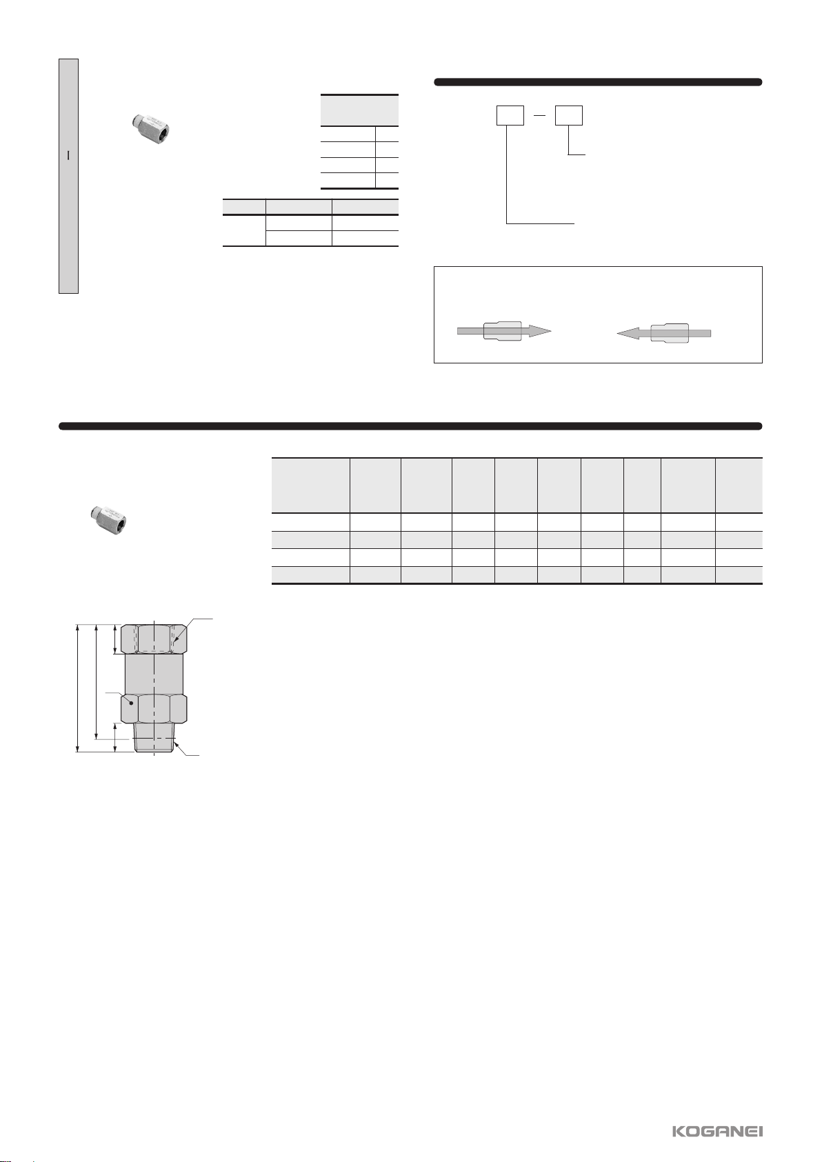
Handling Instructions and Precautions
Precautions for mounting the body
①Use the appropriate tool to tighten the hex nuts on the fitting.
②Refer to the following table of recommended tightening
torques when attaching the threaded parts. If you use more
than the recommended torque when tightening the threaded
parts, you may cause leaks by fracturing the threads or
deforming the gaskets. Also, if you use less than the
recommended torque when tightening the threaded parts, it
may result in looseness or leaks.
Precautions for disconnecting fittings
Tightening threaded parts
①Use the appropriate tool to remove the hex nuts from the
fitting.
②Remove the sealant from the threads on the other parts. If
the sealant is stuck to the other parts, it may get into
peripheral devices and cause a malfunction.
Metric thread
Tapered threads
for pipes
Thread type Thread size
1.5 to 1.9 N•m [13.277 to 16.817 in•lbf]
2 to 2.7 N•m [17.702 to 23.898 in•lbf]
7 to 9 N•m [61.957 to 79.659 in•lbf]
12 to 14 N•m [106.212 to 123.914 in•lbf]
22 to 24 N•m [194.722 to 212.424 in•lbf]
28 to 30 N•m [247.828 to 265.530 in•lbf]
M5×0.8
M6×1
R1/8
R1/4
R3/8
R1/2
Tightening torque
Recommended tightening torque
Precautions for attaching tubes
●Attaching and detaching tubes
①Confirm that the cut surface of the tube is cut straight across,
that the outer surface of the tube is not damaged, and that
the tube has not become oval shaped.
②When connecting tubes, if you do not insert the tube all the
way to the tube end, it may result in leaks.
③After installing the tube, pull on it to check that it does not
come off.
④
Do not meaninglessly press on the release ring before
attaching a tube. Doing so may cause the tube to become
detached.
Tube end
If removing pipes is difficult because the piping space is very
constricted, consult your nearest Koganei sales office for
specialized tools that are available.
Specialized tools for removing tubes
①Tightening threaded parts
Use a wrench on the hex nut to
tighten the threaded parts.
When tightening hex nuts
How to attach and detach tubes
①Attaching tubes
Check valves are equipped with
lock claws that hold tubes in place
when they have been pushed all
the way to the end, and with an
elastic sleeve for sealing the
periphery around the tubes.
②Removing tubes
When removing a tube, pressing
the release ring opens the lock
claw and the tube can be pulled
out.
Be sure to stop the air before
removing tubes.
d
d
c
Precautions for removing tubes
①Before removing tubing, be sure to confirm that the pressure
inside the tubing is zero.
②Uniformly press the release ring inwards as far as it goes
and then pull out the tubing. If you do not fully press in on
the release ring, the tube may not come out, or the tubing
may become scratched causing debris to be left inside the
fitting.
●Mounting
Depending on the usage conditions, check valves may
produce a droning (vibrating) noise. Consult the nearest
Koganei sales office for countermeasures against the noise.
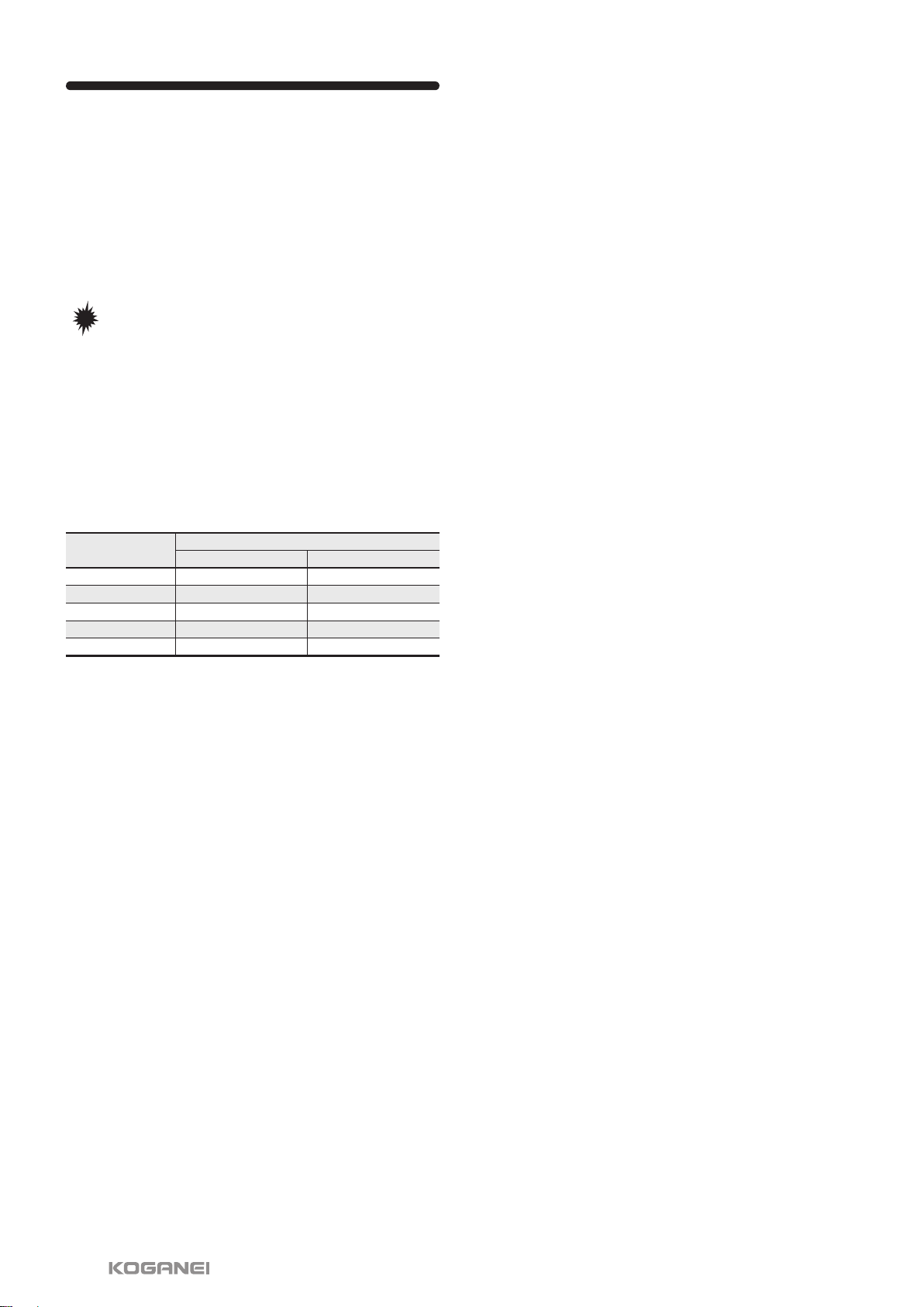
For φ3 [0.118], φ4 [0.157], and φ6 [0.236] tubes
Order codes: UJ-1
For φ6 [0.236], φ8 [0.315], φ10 [0.394], and φ12 [0.472] tubes
Order codes: UJ-2