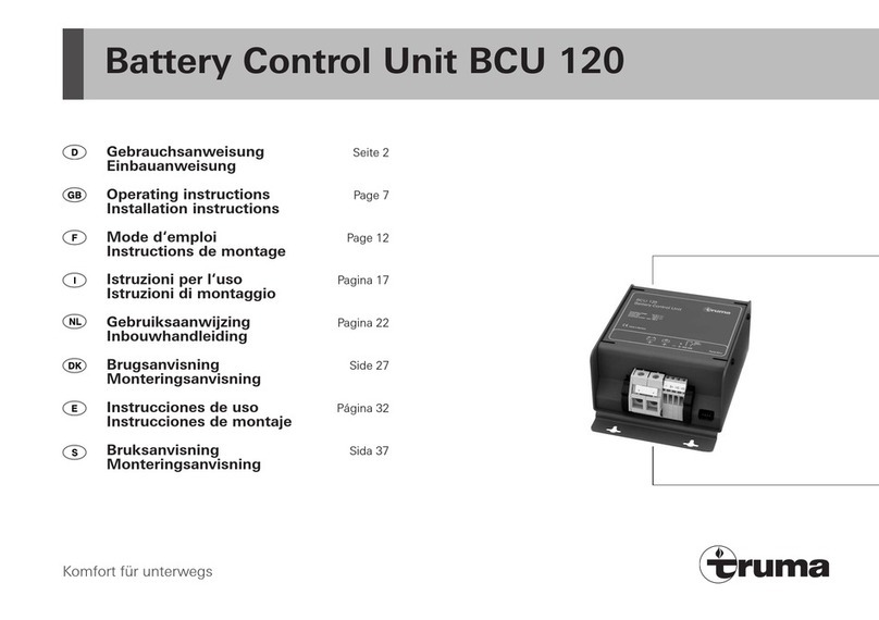
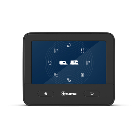
Truma Vicon 2 User manual

Einbauanweisung Seite 2
Installation instructions Page 7
Vicon 2 Power Module / Touch Panel

2
Inhaltsverzeichnis
Sicherheitshinweise .......................................................... 2
Verwendete Symbole ............................................................ 2
Verwendungszweck .............................................................. 2
Einbauanweisung
Touch Panel (TP) ................................................................. 3
Power Module (PM) ........................................................... 3
Anschluss ............................................................................ 4
Anschlussschema ................................................................. 4
Leitungslängen und -querschnitte ........................................ 4
Anschlussplan 12 V-Spannungsversorgung ......................... 4
Anschluss Ladeautomat Truma BC 630 IU ........................... 4
Anschluss Power Module – Power Module .......................... 4
Anschluss Touch Panel ......................................................... 5
Anschluss der Heizung Truma Combi ................................... 5
Anschluss der Heizung Alde Compact 3010 ........................ 5
Anschluss Adaption / Verbraucher ....................................... 5
Schnittstellen ........................................................................ 6
Vicon 2 Power Module / Touch Panel
Sicherheitshinweise
Die Montage und der Anschluss von elektrischen Geräten
muss grundsätzlich durch geeignetes Fachpersonal erfolgen!
Vor Beginn der Arbeiten Einbauanweisung sorgfältig durchle-
sen und befolgen!
Stellen Sie sicher, dass die Stromzufuhr getrennt ist! Netz-
stecker ziehen!
Benutzen Sie zum Anschluss des Gerätes nur die mitgelieferten
Teile sowie die vorgeschriebenen Leitungsquerschnitte und
Sicherungen!
Benutzen Sie nur geeignetes und einwandfreies Werkzeug.
Schließen Sie das Gerät nur gemäß des mitgelieferten An-
schlussplanes an!
Verwendete Symbole
Symbol weist auf mögliche Gefahren hin.
Hinweis mit Informationen und Tipps.
Verwendungszweck
Das Gerät ist für den Einbau in Caravans und Motorcaravans
bestimmt.
Konformitätserklärung
Das Gerät erfüllt die Anforderungen folgender EG-Richtlinien:
– Altfahrzeug-Richtlinie 2000/53/EG
Das Gerät erfüllt die Anforderungen folgender
UN ECE-Regelungen:
– Funkentstörung in KFZ UN ECE R10
Typgenehmigungsnummer E1 10R-035550
Technische Änderungen vorbehalten!

3
Der Einbau in Fahrzeuge muss den technischen und adminis-
trativen Bestimmungen des jeweiligen Verwendungslandes
entsprechen (z. B. EN 1648, VDE 0100-721). Nationale Vor-
schriften und Regelungen müssen beachtet werden.
In anderen Ländern sind die jeweils gültigen Vorschriften zu
beachten.
Touch Panel (TP)
Max. 1 Touch Panel kann pro installiertem
Vicon 2 Bus System über einen Y-Adapter (Y) ange-
schlossen werden.
Das Touch Panel an einer vor Feuchtigkeit und Nässe ge-
schützten Stelle einbauen.
Einbauöffnung für das Touch-Display herstellen.
148
max. 3
125
89
98
Maße in mm.
Das Kabel vom Y-Adapter z. B. am Stecker X 1 anstecken.
Den offenen Stecker X 2 zwingend mit einem Abschlusswi-
derstand R = 120 Ω (Art.Nr. C30000-00300) abschließen.
Ein Kabelabgang ist seitlich oder nach oben möglich.
Das Kabel zur Zugentlastung in die Kabelführungen
einlegen.
X 1
X 2
X
1
X
2
Das Kabel durch die Einbauöffnung schieben und zum
Y-Adapter verlegen.
Das Touch Panel mit 4 Schrauben befestigen (max. 3 mm
Außendurchmesser, max. Drehmoment 1 Nm).
≤ 1 Nm
Den Rahmen auf das Touch Panel drücken, bis er einrastet.
–
–
–
–
–
–
–
–
Einbauanweisung Power Module (PM)
Das Power Module an einer vor Feuchtigkeit und Nässe ge-
schützten Stelle (Wand oder Boden) einbauen.
Das Power Module muss frei zugänglich installiert werden,
ohne Verkleidungsteile etc. zu zerstören.
Um einen einfachen Service zu ermöglichen empfiehlt
Truma – statt eines Abschlusswiderstandes – einen frei
zugänglichen Diagnosestecker (Art.-Nr. C30000-00400) im
System zu installieren.
Einbaumaße
170170
172
36,3
Maße in mm.
Abnehmen der Gehäuseabdeckung
11 2
3
Minimaler Einbauraum
Zum Abnehmen der Gehäuseabdeckung muss eine ent-
sprechend große Zugangsöffnung im Innenraum vorhanden
sein. Wird der Zugang verschlossen, einen Mindestabstand
von 15 mm zur Gehäuseabdeckung einhalten.
Gerät mit 2 Schrauben befestigen (keine Senkkopf-
schrauben, max. Drehmoment 1 Nm).
60
80 166
52
312
70
310
Ø 4,5
154,5
≤ 1 Nm
Maße in mm.
–
–
–

4
Anschluss
Vor dem Anschließen oder Trennen von Leitungen sind
die Versorgungsleitungen von Batterie und Netz zu
trennen!
Darauf achten, dass alle Stecker eingerastet sind.
Anschlussschema
230 V ~ L
N
PE
12 V
Y
R
Alde
Compact
3010
Truma
Combi
... AVI
TP
PM PM PM
R
TA
CAN CAN CAN
F
Rs
F
S
...
Ü
Tr
S5
TP Vicon 2 Touch Panel
PM Powermodul
AVI Alde-Vicon-Interface
A Alde Raumtemperaturfühler
CAN CAN-BUS
F Sicherung
R Abschlusswiderstand 120 Ω
Rs Shunt
Y Y-Adapter
T Truma Raumtemperaturfühler
Tr Ringkerntransformator
Ü Adapter (Überlastungsschutz)
Leitungslängen und -querschnitte
Leitung Leitungs-
länge Leitungs-
querschnitt
W1 Muss je nach Fahrzeug / Konfiguration
festgelegt werden.
CAN – 25 m ≥ 0,22 mm²
Anschluss Energiequelle
Verbinden Sie das Gerät gemäß Anschlussplan mit der
Energiequelle (z. B. Batterie, Lichtmaschine, Ladeautomat).
Achten Sie auf den richtigen Anschluss der Pole.
Sicherungen unbedingt nahe der Energiequelle (z. B.
Batterie, Lichtmaschine, Ladeautomat) anbringen. Nur
vorgeschriebene Leitungsquerschnitte (siehe Tabelle) und
Sicherungsstärken verwenden!
Anschlussplan 12 V-Spannungsversorgung
Beispiel: 12 V-Spannungsversorgung für ein Power Modul.
12 V
–12 V
-
Y
+Y W1 W1
+
S
Curr. Mon.
-
Batt. Comm.
Curr. Mon.+
F
F
Rs
S3
F
F
1 ≤ 2,2 Nm
2
3
4
1 M 5 x 10 Innensechskant, max. Drehmoment 2,2 Nm
2 Fächerscheibe für M5
3 Scheibe
4 12 V-Anschluss über Kabelschuh (M5) max. 16 mm²
F Sicherung
Rs Shunt
S Hauptschalter
Y Y-Adapter 12 V-Anschluss über Kabelschuh
Anschluss Ladeautomat Truma BC 630 IU
Der Ladeautomat Truma BC 630 IU muss über einen
LKL-Adapter (Art.-Nr. C30000-00500) angeschlossen
werden.
Anschluss Power Module – Power Module
Die Anschlüsse COM1 und COM2 können sowohl als Eingang
oder Ausgang genutzt werden.
Die Module (PM) untereinander verbinden. Den Anschluss
COM2 mit dem Anschluss COM1 des folgenden Moduls
verbinden.
Den Anschluss COM2 des letzten Moduls zwingend mit
einem Abschlusswiderstand (Art-Nr. C30000-00300)
abschließen.
COM2
COM1
COM2
COM1
COM2
COM1
COM2
COM1
COM2
COM1
R
PMPMPM
CAN CAN
CAN
Die Zugentlastung der Kabel erfolgt durch den Deckel.
–
–

5
Anschluss Touch Panel
Das Touch Panel (TP) ausschließlich über einen Y-Adapter (Y)
an ein Power Module (PM) anschließen.
Den Y-Adapter (Art.-Nr. C30000-03300) an einer vor Feuchtig-
keit und Nässe geschützten Stelle (Wand oder Boden) nahe
dem Power Module (PM) einbauen. Gegebenenfalls den
Y-Adapter mit Kabelbinder befestigen.
R
COM2
COM1
COM1
Y
PM
TP
-
Y
+Y
Die Anschlusskabel des Y-Adapters dürfen nicht verlän-
gert werden.
Anschluss der Heizung Truma Combi
Für den Anschluss der Heizung, am Anschluss COM3 eines
Moduls (PM), ist ein TIN-Kabel erforderlich.
COM2
COM1
COM2
COM1
COM2
COM1
COM3
COM3
R
PM
PM
PM
Combi
TIN
CAN CAN
CAN
TIN TIN-Kabel 3 m (Art. Nr.: C30000-05000)
TIN-Kabel 6 m (Art. Nr.: C30000-05100)
Anschluss der Heizung Alde Compact 3010
Für den Anschluss der Alde Heizung Compact 3010 an das
Vicon 2 Bus System ist ein Interface (AVI) erforderlich.
Das Gerät über das Interface mit COM3 eines Moduls (PM)
verbinden.
Der Alde Raumtemperaturfühler (A) muss am AVI ange-
schlossen werden.
COM2
COM1
COM2
COM1
COM2
COM1
COM3
COM3
R
PM
PM
PM
TIN
CAN CAN
CAN
Alde
Compact
3010
AVI
A
A Alde Raumtemperaturfühler
AVI Alde-Vicon-Interface (Art.-Nr. C30000-03500)
TIN TIN-Kabel 3 m (Art. Nr.: C30000-05000)
TIN-Kabel 6 m (Art. Nr.: C30000-05100)
Anschluss Adaption / Verbraucher
Die Adaption des Anschlusses (der Verbraucher) erfolgt
nur über den Fahrzeughersteller.

6
Schnittstellen
Passende Kabel und Stecker sind über Truma lieferbar.
COM1
I2
I3
I4
I5
I6
I7
I8
I9
I10
I1
COM2
COM3
+
-
S1
S2
S3
S4
S5
GND
O10O9O8O7O6O5O4O3O2O1 O11
GND
CAN-Bus
Bezeichnung
COM1
COM2 CAN I
CAN II CAN-H
GND
CAN-L
GND
Sensoreingänge
Bezeichnung
S1 Füllstandssonde
gestuft 100%
50%
75%
25%
GND
S2 Ladekontrolle
N.C.
Tremat, D+/-
LKL
GND
S3 Batteriemonitor U/I Curr. Mon.+
Curr. Mon.-
Batt. Comm.
S4 Temperatursensor Sensor Temp.
GND
S5 Füllstandssonde
stufenlos
N.C.
AGND
0…4 V
GND
+12 V
TIN-Bus
Bezeichnung
COM3 TIN-Bus
Steuereingänge
Bezeichnung
I1 – I6
I9
I10
gegen Masse
schaltend
–
GND
I7, I8 gegen Masse
oder
+12 V schaltend
(konfigurierbar)
–
Lastanschlüsse
Anschluss über Flachsteckhülse 6,3 mm.
GND
O9O7O5O3 O10O8O6O4O2
O1 O11
Bezeichnung
GND 10 Anschlüsse für
Masse
O1 12 V-Ausgang 1
O2 12 V-Ausgang 2
O3 12 V-Ausgang 3 Dimmbar
O4 12 V-Ausgang 4
O5 12 V-Ausgang 5
O6 12 V Ausgang 6 Parallelschaltung
(Drahtbrücke) mit An-
schluss O8 möglich.
O7 12 V Ausgang 7
O8 12 V Ausgang 8 Parallelschaltung
(Drahtbrücke) mit An-
schluss O6 möglich.O9
O10 12 V-Ausgang 9 Schaltbar als
H-Brücke
O11 12 V-Ausgang 10

7
Vicon 2 Power Module / Touch Panel
Safety instructions
Only qualified technicians may assemble and connect electri-
cal devices!
Read the installation instructions carefully prior to starting
work and observe the instructions!
Ensure that the power supply has been disconnected! Discon-
nect the mains plug!
Only use the supplied parts and the specified cable cross-sec-
tions and fuses to connect the device!
Only use suitable and fully functional tools.
Only wire the device as specified in the supplied wiring
diagram!
Symbols used
Symbol indicates a possible hazard.
Comment including information and tips.
Application purpose
The device is designed for installation in caravans and
campers.
Declaration of conformity
The device meets the requirements of the following
EC Directives
End-Of-Life Vehicle Directive 2000/53/EC
The device fulfils the requirements of the following UN ECE
regulations:
Radio Interference in Vehicles UN ECE R10
type approval number E1 10R-035550
The right to effect technical modifications is reserved!
–
–
Table of contents
Safety instructions ............................................................ 7
Symbols used ....................................................................... 7
Application purpose .............................................................. 7
Installation instructions
Touch Panel (TP) ................................................................. 8
Power Module (PM) ........................................................... 8
Connection .......................................................................... 9
Connecting diagram .............................................................. 9
Cable length and cross-section ............................................ 9
Wiring diagram 12 V voltage supply ..................................... 9
Automatic Charger Truma BC 630 IU connection ................ 9
Power Module – Power Module connection ........................ 9
Touch Panel connection ...................................................... 10
Connecting the Truma Combi heating ................................ 10
Connecting the Alde Compact 3010 heating ...................... 10
Adaption / consumers connection ...................................... 10
Interfaces ............................................................................ 11
8
Installation in vehicles must accord with the technical and
administrative provisions of the individual country of use (e.g.
EN 1648, VDE 0100-721). The national legislation and regula-
tions must be observed.
In other countries always observe the respectively valid
regulations.
Touch Panel (TP)
Max. 1 Touch Panel can be connected per installed
Vicon 2 bus system using a Y-adapter (Y).
Install the Touch Panel in a place protected against moisture
and wetness.
Produce an installation opening for the Touch-Display.
148
max. 3
125
89
98
All dimensions in mm.
Plug in the cable from the Y-adapter (e.g. at plug X 1).
It is compulsory that the open plug X 2 is closed off with a
terminating resistor R = 120 Ω (part no. C30000-00300).
A cable outlet is possible to the side or top.
Insert the cable for strain relief into the cable guide.
X 1
X 2
X
1
X
2
Push the cable through the installation opening and lay to
the Y-adapter.
Fix the Touch Panel with 4 screws (max. 3 mm outer diam-
eter, max. torque 1 Nm).
≤ 1 Nm
Press the frame onto the Touch Panel until it clicks in place.
–
–
–
–
–
–
–
–
Installation instructions Power Module (PM)
Install the Power Module in a place (wall or floor) protected
against moisture and wetness.
The Power Module must be installed in a freely accessible
position without disturbing any cover elements etc.
In order to allow easier servicing, Truma recommends
installing a freely accessible diagnosis plug (part no.
C30000-00400) in the system instead of a terminating
resistor.
Installation dimensions
170170
172
36.3
All dimensions in mm.
Removing the housing cover
11 2
3
Minimum installation space
To detach the housing cover, a suitably sized access opening
must be available inside. Maintain a minimum clearance of
15 mm to the housing cover if the access is closed.
Fix the device with 2 screws (no countersunk screws, max.
torque 1 Nm). ´
60
80 166
52
312
70
310
Ø 4,5
154.5
≤ 1 Nm
All dimensions in mm.
–
–
–

9
Connection
Before connecting or disconnecting the cables, the
supply lines to the battery and mains supply must be
disconnected!
Make sure that all plugs have clicked in place.
Connecting diagram
230 V ~ L
N
PE
12 V
Y
R
Alde
Compact
3010
Truma
Combi
... AVI
TP
PM PM PM
R
TA
CAN CAN CAN
F
Rs
F
S
...
Ü
Tr
S5
TP Vicon 2 Touch Panel
PM Powermodul
AVI Alde-Vicon-Interface
A Alde room temperature sensor
CAN CAN-BUS
F Fuse
R Terminating resistor 120 Ω
Rs Shunt
Y Y-Adapter
T Truma room temperature sensor
Tr Toroidal transformer
Ü Adapter (overload protector)
Cable length and cross-section
Cable Cable
length Cable
cross-section
W1 Must be specified depending on the
vehicle / configuration.
CAN – 25 m ≥ 0,22 mm²
Energy source connection
Connect the device with the energy source (e.g. battery,
generator or automatic charger). Pay attention to correct
connection of the pole.
Fuses must be attached near to the source of energy
(e.g. battery, generator or automatic charger). Only
use the stipulated cable cross-sections (see table) and fuse
ratings!
Wiring diagram 12 V voltage supply
Example: 12 V voltage supply for a Power Module.
12 V
–12 V
-
Y
+Y W1 W1
+
S
Curr. Mon.
-
Batt. Comm.
Curr. Mon.+
F
F
Rs
S3
F
F
1 ≤ 2.2 Nm
2
3
4
1 M 5 x 10 hexagon socket, max. torque 2.2 Nm
2 Serrated washer for M5
3 Washer
4 12 V connection using eyelet connector (M5) max. 16 mm²
F Fuse
Rs Shunt
S Main switch
Y Y-adapter 12 V connection using eyelet connector
Automatic Charger Truma BC 630 IU
connection
The Automatic Charger Truma BC 630 IU must be con-
nected using a LKL adapter (part no. C30000-00500).
Power Module – Power Module connection
The COM1 and COM2 connections can be used both as an
input or output.
Connect the (PM) modules with each other. Connect
the COM2 connection with the COM1 connection of the
following module.
It is compulsory to connect the COM2 connector of the last
module with a terminating resistor (part no. C30000-00300)
COM2
COM1
COM2
COM1
COM2
COM1
COM2
COM1
COM2
COM1
R
PMPMPM
CAN CAN
CAN
Strain relief for the cable is provided by the cover.
–
–

10
Touch Panel connection
Only connection the Touch Panel (TP) using a Y-adapter (Y) to
a Power Module (PM).
Install the Y-adapter (part no. C30000-03300) in a place (wall
or floor) protected against moisture and wetness close to
the Power Module (PM). Fix the Y-adapter with cable ties if
necessary.
R
COM2
COM1
COM1
Y
PM
TP
-
Y
+Y
The Y-adapter connection cables may not be extended.
Connecting the Truma Combi heating
A TIN cable is necessary for connection of the heating to the
COM3 connection of a module (PM).
COM2
COM1
COM2
COM1
COM2
COM1
COM3
COM3
R
PM
PM
PM
Combi
TIN
CAN CAN
CAN
TIN TIN cable 3 m (part no. C30000-05000)
TIN cable 6 m (part no. C30000-05100)
Connecting the Alde Compact 3010 heating
An interface (AVI) is necessary to connection the Alde heating
Compact 3010 to the Vicon 2 bus system.
Connect the device using the interface with COM3 of a
module (PM).
The Alde room temperature sensor (A) must be
connected at the AVI.
COM2
COM1
COM2
COM1
COM2
COM1
COM3
COM3
R
PM
PM
PM
TIN
CAN CAN
CAN
Alde
Compact
3010
AVI
A
A Alde Room temperature sensor
AVI Alde-Vicon-Interface (part no. C30000-03500)
TIN TIN cable 3 m (part no. C30000-05000)
TIN cable 6 m (part no. C30000-05100)
Adaption / consumers connection
Adaption of the connection (of consumers) only takes
place through the vehicle manufacturer.

11
Interfaces
The right cables and plugs are available from Truma.
COM1
I2
I3
I4
I5
I6
I7
I8
I9
I10
I1
COM2
COM3
+
-
S1
S2
S3
S4
S5
GND
O10O9O8O7O6O5O4O3O2O1 O11
GND
CAN-Bus
Name
COM1
COM2 CAN I
CAN II CAN-H
GND
CAN-L
GND
Sensor inputs
Name
S1 Filling level sensor
Progressive 100%
50%
75%
25%
GND
S2 Charge control
N.C.
Tremat, D+/-
LKL
GND
S3 Battery
monitor U/I Curr. Mon.+
Curr. Mon.-
Batt. Comm.
S4 Temperature
sensor
Sensor Temp.
GND
S5 Filling level sensor
Infinitely viable
N.C.
AGND
0…4 V
GND
+12 V
TIN-Bus
Name
COM3 TIN-Bus
Control inputs
Name
I1 – I6
I9
I10
Switched to
earth
–
GND
I7, I8 Switched to
earth or
+12 V (can be
configured)
–
Load connections
Connection using flat connector 6.3 mm.
GND
O9O7O5O3 O10O8O6O4O2
O1 O11
Name
GND 10 connections
for earth
O1 12 V output 1
O2 12 V output 2
O3 12 V output 3
Dimmable
O4 12 V output 4
O5 12 V output 5
O6 12 V output 6 Parallel circuit (wire
bridge) possible with
connection O8.
O7 12 V output 7
O8
12 V output 8 Parallel circuit (wire
bridge) possible with
connection O6.
O9
O10 12 V output 9 Switchable as an
H-bridge
O11 12 V output 10

In Deutschland ist bei Störungen grundsätzlich
das Truma Servicezentrum zu benachrichtigen; in
anderen Ländern stehen die jeweiligen Service-
partner zur Verfügung (siehe Truma Serviceheft
oder www.truma.com).
Für eine rasche Bearbeitung halten Sie bitte
Gerätetyp und Fabriknummer (siehe Typenschild)
bereit.
In Germany, always notify the Truma Service Centre
if problems are encountered; in other countries the
relevant service partners should be contacted (see
Truma Service Booklet or www.truma.com).
Having the equipment model and the serial number
ready (see type plate) will speed up processing.
C11000-88500 · 00 · 03/2011 ·
Truma Gerätetechnik GmbH & Co. KG
Wernher-von-Braun-Straße 12
85640 Putzbrunn
Deutschland
Service
Telefon +49 (0)89 4617-2142
Telefax +49 (0)89 4617-2159
www.truma.com
Fo ©
Table of contents
Languages:
Other Truma Control Unit manuals

Truma
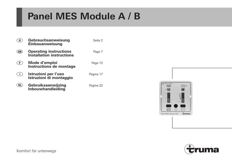
Truma Panel MES Module A Operating instructions

Truma
Truma iNet X User manual

Truma
Truma FrostControl User manual

Truma
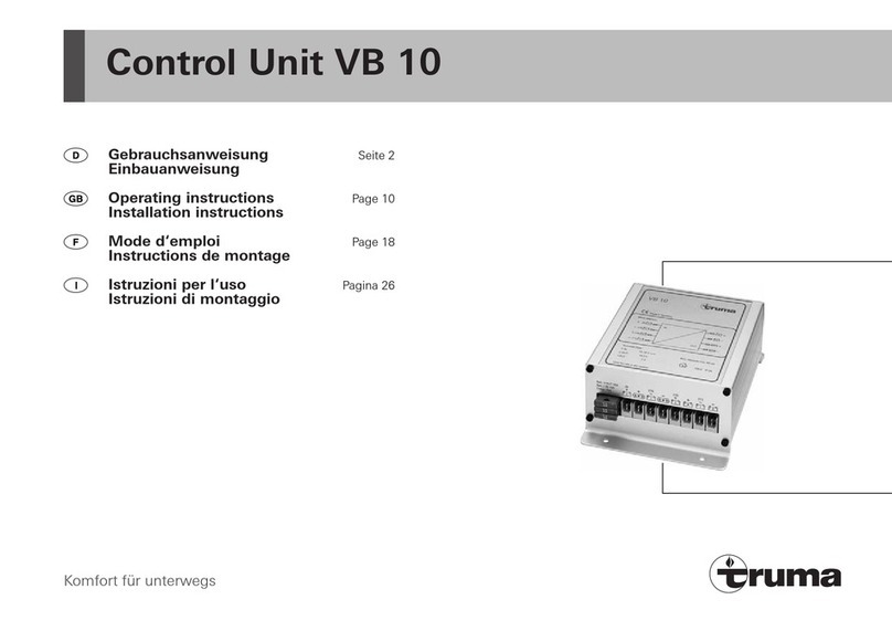
Truma VB 10 Operating instructions

Truma
Truma CP 25-UK User manual

Truma
Truma BCU 120 Operating instructions

Truma
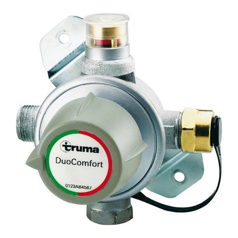
Truma DuoComfort User manual

Truma
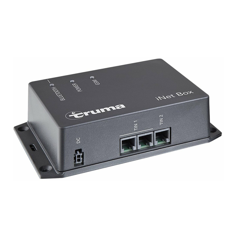
Truma iNet Box User manual

Truma
Truma iNet Box User manual

Truma
Truma iNet Box User manual
Popular Control Unit manuals by other brands

Renishaw
Renishaw A-2028-7574 installation guide

Honeywell
Honeywell V5004TF installation instructions

tams elektronik
tams elektronik PZS-2 Series manual

ESBE
ESBE ALA223 Series manual

HMS Networks
HMS Networks Ewon Flexy Series installation guide

Telit Wireless Solutions
Telit Wireless Solutions GE866-QUAD Hardware user's guide