Geokon 4500S User manual

Instruction Manual
Model 4500 series
Vibrating Wire Piezometer
No part of this instruction manual may be reproduced, by any means, without the written consent of Geokon, Inc.
The information contained herein is believed to be accurate and reliable. However, Geokon, Inc. assumes no responsibility for
errors, omissions or misinterpretation. The information herein is subject to change without notification.
Copyright © 2003-2017 by Geokon, Inc.
(REV CC, 2/2/2017)


Warranty Statement
Geokon, Inc. warrants its products to be free of defects in materials and workmanship, under normal use
and service for a period of 13 months from date of purchase. If the unit should malfunction, it must be
returned to the factory for evaluation, freight prepaid. Upon examination by Geokon, if the unit is found
to be defective, it will be repaired or replaced at no charge. However, the WARRANTY is VOID if the
unit shows evidence of having been tampered with or shows evidence of being damaged as a result of
excessive corrosion or current, heat, moisture or vibration, improper specification, misapplication, misuse
or other operating conditions outside of Geokon's control. Components which wear or which are damaged
by misuse are not warranted. This includes fuses and batteries.
Geokon manufactures scientific instruments whose misuse is potentially dangerous. The instruments are
intended to be installed and used only by qualified personnel. There are no warranties except as stated
herein. There are no other warranties, expressed or implied, including but not limited to the implied
warranties of merchantability and of fitness for a particular purpose. Geokon, Inc. is not responsible for
any damages or losses caused to other equipment, whether direct, indirect, incidental, special or
consequential which the purchaser may experience as a result of the installation or use of the product. The
buyer's sole remedy for any breach of this agreement by Geokon, Inc. or any breach of any warranty by
Geokon, Inc. shall not exceed the purchase price paid by the purchaser to Geokon, Inc. for the unit or
units, or equipment directly affected by such breach. Under no circumstances will Geokon reimburse the
claimant for loss incurred in removing and/or reinstalling equipment.
Every precaution for accuracy has been taken in the preparation of manuals and/or software,
however, Geokon, Inc. neither assumes responsibility for any omissions or errors that may
appear nor assumes liability for any damages or losses that result from the use of the products in
accordance with the information contained in the manual or software.

TABLE of CONTENTS
1. THEORY OF OPERATION ................................................................................................... 1
2. QUICK START INSTRUCTIONS......................................................................................... 2
3. PRIOR TO INSTALLATION................................................................................................. 2
3.1 SATURATING FILTER TIPS....................................................................................................... 2
3.1.1 Piezometers with low air entry (standard) filter housings.............................................. 2
3.1.2 Model 4500S equipped with option High Air Entry Ceramic Filter............................... 3
3.1.3 Model 4500C................................................................................................................... 4
3.2 ESTABLISHING AN INITIAL ZERO READING............................................................................. 5
3.2.1 Recommended method: ................................................................................................... 6
3.2.2 Alternative method 1:...................................................................................................... 6
3.2.3 Alternative method 2:...................................................................................................... 6
3.2.4 Alternative method 3:...................................................................................................... 6
3.3 CHECKING THE PIEZOMETER PERFORMANCE.......................................................................... 7
4. INSTALLATION...................................................................................................................... 8
4.1 INSTALLATION IN STANDPIPES OR WELLS............................................................................... 8
4.2 INSTALLATION IN BOREHOLES................................................................................................ 9
4.3 INSTALLATION IN FILLS AND EMBANKMENTS....................................................................... 12
4.4 INSTALLATION BY PUSHING OR DRIVING INTO SOFT SOILS................................................... 14
4.5 MODEL 4500H AND MODEL 4500HH TRANSDUCER ............................................................ 15
4.6 SPLICING AND JUNCTION BOXES........................................................................................... 16
4.7 LIGHTNING PROTECTION....................................................................................................... 17
5. TAKING READINGS............................................................................................................ 18
5.1 GK-404 READOUT BOX........................................................................................................ 18
5.1.1 Operating the GK-404................................................................................................... 18
5.2 GK-405 READOUT BOX........................................................................................................ 19
5.2.1 Connecting Sensors....................................................................................................... 19
5.2.2 Operating the GK-405................................................................................................... 19
5.3 GK-403 READOUT BOX (OBSOLETE MODEL)....................................................................... 20
5.3.1 Connecting Sensors....................................................................................................... 20
5.3.2 Operating the GK-403................................................................................................... 20
5.4 MEASURING TEMPERATURES................................................................................................ 21
6. DATA REDUCTION.............................................................................................................. 22
6.1 PRESSURE CALCULATION ..................................................................................................... 22
6.2 TEMPERATURE CORRECTION ................................................................................................ 24
6.3 BAROMETRIC CORRECTION (REQUIRED ONLY ON UNVENTED TRANSDUCERS) ...................... 25
6.4 VENTED PIEZOMETERS ......................................................................................................... 26
6.5 ENVIRONMENTAL FACTORS.................................................................................................. 26


7. TROUBLESHOOTING......................................................................................................... 27
APPENDIX A. - SPECIFICATIONS........................................................................................ 29
A.1 STANDARD PIEZOMETER WIRING ........................................................................................ 29
APPENDIX B. - THERMISTOR TEMPERATURE DERIVATION................................... 30
APPENDIX C. HIGH TEMPERATURE THERMISTOR LINEARIZATION................... 31
APPENDIX D. IMPROVING THE ACCURACY OF THE CALCULATED PRESSURE32
APPENDIX E. - MODEL 4500AR PIEZOMETER................................................................ 32

FIGURES
FIGURE 1-MODEL 4500S VIBRATING WIRE PIEZOMETER .............................................................. 1
FIGURE 2-4500C SATURATION....................................................................................................... 4
FIGURE 3-TYPICAL LEVEL MONITORING INSTALLATION................................................................ 8
FIGURE 4-TYPICAL BOREHOLE INSTALLATIONS........................................................................... 10
FIGURE 5-HIGH AIR ENTRY FILTER.............................................................................................. 12
FIGURE 6-LOW AIR ENTRY FILTERS ONLY................................................................................. 13
FIGURE 7-TYPICAL SOFT SOILS INSTALLATION............................................................................ 14
FIGURE 8-TYPICAL MULTI-PIEZOMETER INSTALLATION.............................................................. 16
FIGURE 9-RECOMMENDED LIGHTNING PROTECTION SCHEME...................................................... 17
FIGURE 10 -LEMO CONNECTOR TO GK-404.................................................................................. 18
FIGURE 11 -LIVE READINGS –RAW READINGS............................................................................. 19
FIGURE 12 -TYPICAL CALIBRATION REPORT................................................................................. 23
FIGURE 13 -4500AR ..................................................................................................................... 33
TABLES
TABLE 1-CEMENT/BENTONITE/WATER RATIOS............................................................................ 11
TABLE 2-ENGINEERING UNITS MULTIPLICATION FACTORS.......................................................... 23
TABLE 3-SAMPLE RESISTANCE..................................................................................................... 27
TABLE 4-RESISTANCE WORK SHEET............................................................................................ 27
TABLE 5-VIBRATING WIRE PIEZOMETER SPECIFICATIONS........................................................... 29
TABLE 6-STANDARD PIEZOMETER WIRING.................................................................................. 29
TABLE 7-THERMISTOR RESISTANCE VERSUS TEMPERATURE........................................................ 30
TABLE 8- THERMISTOR RESISTANCE VERSUS TEMPERATURE FOR HIGH TEMPERATURE MODELS . 31
EQUATIONS
EQUATION 1-DIGITS CALCULATION ............................................................................................. 22
EQUATION 2-CONVERT DIGITS TO PRESSURE............................................................................... 22
EQUATION 3-TEMPERATURE CORRECTION................................................................................... 24
EQUATION 4-BAROMETRIC CORRECTION..................................................................................... 25
EQUATION 5-CORRECTED PRESSURE CALCULATION.................................................................... 25
EQUATION 6-RESISTANCE TO TEMPERATURE............................................................................... 30
EQUATION 7-HIGH TEMPERATURE RESISTANCE TO TEMPERATURE ............................................. 31

1
1. THEORY OF OPERATION
Geokon model 4500 Vibrating Wire Piezometers are intended primarily for long-term
measurements of fluid depths, and pore pressures in standpipes, boreholes, embankments,
pipelines, and pressure vessels. Several different models are available to suit a variety of
Geotechnical applications. Calibration data is supplied with each piezometer.
All Geokon vibrating wire piezometers utilize a sensitive stainless steel diaphragm (with the
exception of model 4500C, which employs bellows) to which a vibrating wire element is
connected. During use, changing pressures on the diaphragm cause it to deflect. This deflection
is measured as a change in tension and frequency of vibration of the vibrating wire element. The
square of the vibration frequency is directly proportional to the pressure applied to the
diaphragm. A filter is used to keep out solid particles and prevent damage to the sensitive
diaphragm. Standard filters are 50 micron stainless steel. High air entry value filters are available
upon request.
Two coils, one with a magnet insert, the other with a pole piece insert, are installed near the
vibrating wire. In use, a pulse of varying frequency (swept frequency) is applied to these coils,
causing the wire to vibrate primarily at its resonant frequency. When the excitation ends, the
wire continues to vibrate. During vibration a sinusoidal signal is induced in the coils and
transmitted to the readout box where it is conditioned and displayed.
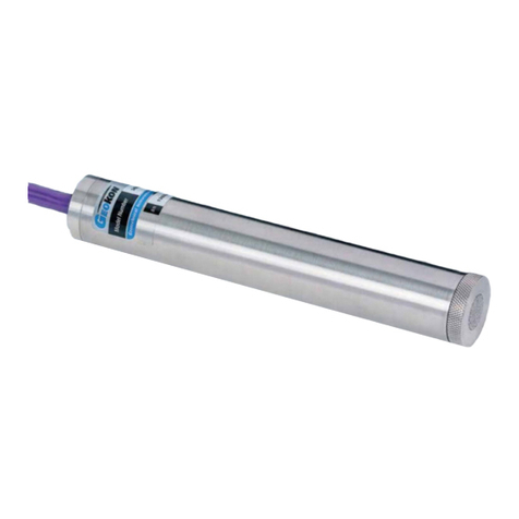
Figure 1 - Model 4500S Vibrating Wire Piezometer
All exposed components are made of corrosion resistant stainless steel. If proper installation
techniques are used, the device should have an unlimited life.
In salt water it may be necessary to use special materials for the diaphragm and housing. The
4500TI series piezometers are constructed from titanium and are specifically designed to be used
in this type of environment.
Portable readout units are available to provide the excitation, signal conditioning, and readout of
the instrument. See Section 5 for instructions on using Geokon readouts with vibrating wire
piezometers. Datalogger systems which allow remote, unattended data collection of multiple
sensors are also available. Contact Geokon for additional information.

2
2. QUICK START INSTRUCTIONS
For those familiar with Geotechnical instrumentation and its installation, the following quick
start instructions may be used. For more detailed instructions see Sections 3 and 4.
1) Prior to installation, allow the piezometer to come to thermal equilibrium with the ambient
temperature for a minimum of 15 minutes. (Alternatively, if the instrument is attached to a
readout box, wait until the piezometer reading has stabilized.)
2) Take an initial zero reading at zero (atmospheric) pressure.
3) Verify that the initial zero reading is compatible with the factory supplied zero reading on the
calibration sheet.
4) Record the barometric pressure and the temperature.
5) Carefully measure and mark the cable where it will lie at the top of the borehole, well, or
standpipe, once the piezometer has reached the desired depth. (The piezo diaphragm lies 3/4
of an inch above the tip of the piezometer.)
6) Saturate the piezometer filter. (See Section 3.1)
7) For installation in standpipes or wells see Section 4.1, for boreholes Section 4.2, and for fills
and embankments Section 4.3.
3. PRIOR TO INSTALLATION
3.1 Saturating Filter Tips
Caution! - Do not allow the piezometer to freeze once it has been filled with water!
Most Geokon filter tips can be removed for saturation and then reassembled. To maintain
saturation, the unit should be kept underwater until installation. (IMPORTANT: The filter stone
and housing of model 4500C piezometers are not removable. Any attempt to remove the filter
stone or the housing will destroy the transducer!)
The saturation procedures are as follows:
3.1.1 Piezometers with low air entry (standard) filter housings
For accurate results, total saturation of the filter is necessary. For low air entry filters no
this saturation occurs as the tip is lowered into the water. Water is forced into the filter,
compressing the air in the space between the filter stone and the pressure sensitive
diaphragm. After a period of time, this air will dissolve into the water, filling the filter
and the space above it entirely with water.
To speed up the saturation process, remove the filter from the piezometer by carefully
twisting and pulling on the filter housing assembly (or unscrewing the point of the
piezometer for model 4500DP). Holding the piezometer so the filter is facing up, fill the
space above the diaphragm with water. Next, slowly replace the filter housing, allowing
the water to squeeze through the filter stone as it is installed. For piezometers with a
range of less than 10 psi, take readings with a readout box while reinstalling the filter
housing to ensure the piezometer is not overranged.

3
If the piezometer is used in a standpipe where it is raised and lowered frequently, the
filter housing may loosen over time, and a permanent filter assembly may be required.
The removable filter may be fixed permanently by prick punching the piezometer tube
approximately 1/16" to 1/8" behind the filter assembly joint.
Filter stones may be replaced with screens for standpipe installations. Salts in the water
can be deposited into the filter causing it to become clogged if it is allowed to dry out
completely. Screens available from Geokon are less likely than standard filters to collect
salt and become clogged.
3.1.2 Model 4500S equipped with option High Air Entry Ceramic Filter
Because of the high air entry characteristics of the ceramic filter, de-airing is particularly
important. Different air entry values require different saturation procedures.
One Bar Filters:
1) Remove the filter from the piezometer by carefully twisting and pulling on the filter
housing assembly.
2) Boil the filter assembly in de-aired water.
3) Reassemble the filter housing and piezometer under the surface of a container of de-
aired water. While installing the filter, use a readout box to monitor the diaphragm
pressure. If the piezometer begins to overrange, allow the pressure to dissipate before
pushing further. Be sure that no air is trapped in the transducer cavity.
Two Bar and Higher:
The proper procedure for de-airing and saturating these filters is somewhat complex, it is
recommended that saturation be done at the factory by Geokon. If saturation must be
done in the field, carefully follow the instructions below:
1) Place the assembled piezometer, filter down, in a vacuum chamber which has an inlet
port at the bottom for de-aired water.
2) Close off the water inlet and evacuate the chamber. The transducer should be
monitored while the chamber is being evacuated.
3) When maximum vacuum has been achieved, allow de-aired water to enter the
chamber until it reaches an elevation a few inches above the piezometer filter.
4) Close off the inlet port.
5) Release the vacuum.
6) Observe the transducer output. It may take up to 24 hours for the filter to completely
saturate and the pressure to rise to zero.
7) After saturation, the transducer should be kept in a container of de-aired water until
installation. If de-aired at the factory a special cap is applied to the piezometer to
maintain saturation.

4
3.1.3 Model 4500C
The filter housing is not removable on the 4500C. Any attempt to remove the filter
stone or the housing will destroy the transducer!
If the pressure to be measured is less than 5 psi the filter stone must be saturated. A hand
operated vacuum pump and short length of 1/2" surgical tubing is required. Hand pumps
and tubing are available from the factory. (A hand pump that has been used successfully
is the MityvacII®by Lincoln Industries Corp. of St. Louis, MO.)
The saturation procedure is as follows:
1) Attach the tube to the transducer as shown in Figure 2.
2) Fill the tubing with approximately 2" (5 cm) of water.
3) Attach the other end of the tube to the hand vacuum pump.
4) While holding the transducer so that the water rests on the filter but does not enter the
pump, squeeze the hand pump to initiate a vacuum inside the tubing. This will draw
the air out of the filter and the area behind it, replacing it with water.
5) A vacuum of 20-25" Hg. (50-65 cm Hg.) is sufficient for proper air evacuation.
Figure 2 - 4500C Saturation

5
3.2 Establishing an Initial Zero Reading
Vibrating Wire Piezometers differ from other types of pressure sensors in that they indicate a
reading when no pressure is exerted on the sensor. It is imperative that an accurate initial zero
reading be obtained for each piezometer, as this reading will be used for all subsequent
data reduction.
Generally, the initial zero reading is obtained by reading the instrument prior to installation.
There are several different ways of taking an initial zero reading. The essential element in all
methods is that the piezometer needs to thermally stabilize in a constant temperature
environment while the pressure on the piezometer is barometric only. Because of the way the
piezometer is constructed, it usually takes 15 to 20 minutes for the temperature of all the
different elements to equalize.
A question may arise as to what to do with the filter stone while taking zero readings. If a
standard stainless steel filter is being used, it will not matter if the filter stone is saturated or not.
However, if the piezometer is equipped with a ceramic high air entry filter stone, then it must be
saturated while taking the zero readings.
It will be necessary to measure the barometric pressure only if the piezometer is unvented, and it
will be installed in a location that is subject to barometric pressure changes which require
correction, such as in an open well. A piezometer sealed in place at depth could be recording
pressures in groundwater that is not hydraulically connected to the atmosphere, for which
barometric pressure compensation would be inappropriate. See Section 6.3 for more information
on Barometric corrections.
Calibration data is supplied with each gage, a factory zero reading taken at a specific temperature
and absolute barometric pressure is included. (See Figure 12 in Section 6 for a sample calibration
sheet.) Zero readings at the site should coincide with the factory readings within 50 digits, after
barometric and temperature corrections are made. Barometric pressures change with elevation at
a rate of approximately 3.45kPa (½ psi) per 300meters (1,000 ft.) The factory elevation is +580
feet. All stated barometric readings represent absolute pressure uncorrected for height above sea
level. A thermistor is included inside the body of the piezometer for the measurement of
temperature.
NOTE REGARDING THE 4500C: The construction of this very slender vibrating wire
transducer requires a miniaturization of the internal parts, which consequently are somewhat
delicate. Handle the transducer with care during the installation procedure. Despite taking
every precaution to ensure that the transducer arrives unharmed, it is possible for the zero to shift
during shipment due to rough handling. However, tests have shown that though the zero may
shift, the calibration factors do not change. Therefore it is doubly important that an initial no load
zero reading be taken prior to installation.

6
3.2.1 Recommended method:
1) Saturate the filter stone per Section 3.1
Caution: Do not allow the piezometer to freeze once it has been filled with water.
2) Replace the filter stone.
3) Hang the piezometer in the borehole at a point just above the water.
4) Wait until the piezometer reading has stopped changing.
5) Take the zero and temperature readings.
3.2.2 Alternative method 1:
1) Place the piezometer under water in a bucket.
2) Allow 15 to 20 minutes for the temperature of the unit to stabilize.
3) Lift the piezometer out of the water by the cable only; do not handle the piezometer
housing as body heat from the hand could cause temperature transients.
4) Immediately take a zero and temperature reading.
3.2.3 Alternative method 2:
1) Allow 15 to 20 minutes for the temperature of the unit to stabilize.
2) Lift the piezometer into the air by the cable only; do not handle the piezometer
housing as body heat from the hand could cause temperature transients.
3) Take a zero and temperature reading.
(If this method is chosen be sure that the piezometer is protected from sunlight or sudden
changes of temperature. Wrapping it in some insulating material is recommended.)
3.2.4 Alternative method 3:
1) Lower the piezometer to a known depth marked on the piezometer cable. (The
diaphragm inside the piezometer is located approximately 3/4” (15mm), from the tip.)
2) Use a dip meter to accurately measure the depth to the water surface.
3) After temperature stabilization, read the piezometer pressure.
4) Using the factory calibration constants and a knowledge of the pressure of the water
column above the piezometer (height times density), calculate the equivalent zero
pressure reading if linear regression is used, or the factor C if the second order
polynomial is used.

7
3.3 Checking the Piezometer Performance
If a rough check of the piezometer performance is needed, the following procedure is
recommended:
1) Lower the piezometer to a point near the bottom of a water filled borehole, or below the
surface of a body of water.
2) Allow 15-20 minutes for the piezometer to come to thermal equilibrium.
3) Using a readout box, record the reading at the current depth.
4) Raise the piezometer by a measured increment.
5) Record the reading on the readout box at the new depth.
6) Using the factory calibration factor, calculate the change in water depth.
7) Compare the calculated change in depth with the measured depth increment. The two values
should be roughly the same.
Alternative Method using a dip meter:
1) Lower the piezometer tip to a measured depth below the water surface.
2) Allow 15-20 minutes for the piezometer to come to thermal equilibrium.
3) Using a readout box, record the reading at that level.
4) Calculate the elevation of the water surface using the given calibration factor.
5) Compare the calculated elevation to the elevation measured using the dip meter.
There are a couple of things that can affect this checking procedure:
If the density of the water is not 1gm/cc.
If the water is saline or turbid.
The water level inside the borehole may vary during the test. This is due to the
displacement of water caused by the cable as it is raised and lowered in the borehole. The
smaller the borehole is, the greater the displacement will be. For example, a 4500S-50kPa
piezometer lowered 50 feet below the water column in a one inch (.875 inch ID)
standpipe will displace the water level by more than four feet.

8
4. INSTALLATION
4.1 Installation in Standpipes or Wells
1) Saturate the filter stone and establish an initial zero reading by following the steps outlined in
Section 3.1 and Section 3.2
2) Mark the cable where the top of the well or standpipe will reside once the piezometer has
reached the desired depth. (The piezometer diaphragm lies 3/4 of an inch above the tip of the
piezometer.)
3) Lower the piezometer into the standpipe/well.
4) Be sure the cable is securely fastened to prevent the piezometer from sliding further into the
well and causing an error in the readings.
Figure 3 - Typical Level Monitoring Installation
It is not recommended that piezometers be installed in wells or standpipes where an electrical
pump or cable is nearby. Electrical interference from these sources can cause unstable readings.
If unavoidable, it is recommended that the piezometer be placed inside a piece of steel pipe.
In situations where packers are used in standpipes, special care should be taken to avoid cutting
the cable jacket with the packer, as this could introduce a possible pressure leak in the cable.

9
4.2 Installation in Boreholes
Geokon piezometers can be installed in cased or uncased boreholes, in either single or multiple
piezometer configurations. If pore pressures in a particular zone are to be monitored, careful
attention must be paid to the borehole sealing technique. Two methods of isolating the zone to be
monitored are detailed below.
Boreholes should be drilled without using drilling mud, or with a material that degrades rapidly
with time, such as Revert. The hole should extend six to twelve inches below the proposed
piezometer location, and should be washed clean of drill cuttings. The bottom of the borehole is
then backfilled with clean fine sand up to a point six inches below the desired piezometer tip
location. The piezometer can then be lowered into position. (Preferably, the piezometer will be
encapsulated in a canvas bag containing clean, saturated sand.) While holding the instrument in
position, (a mark on the cable is helpful) fill the borehole with clean fine sand to a point six
inches above the piezometer. Continue by following the instructions for Installations A, B, or C
as detailed below.
Installation A:
Immediately above the area filled with clean fine sand, known as the "collection zone", the
borehole should be sealed by an impermeable bentonite-cement grout mix, or with alternating
layers of bentonite and sand backfill, tamped in place for approximately one foot, followed by
common backfill. (See Figure 4.)
If multiple piezometers are to be used in a single hole, the bentonite-sand plugs should be
tamped in place below and above the upper piezometers, as well as at interval between the
piezometer zones. When using tamping tools special care should be taken to ensure that the
piezometer cable jackets are not cut during installation, as this could introduce a possible
pressure leak in the cable.
Installation B:
The borehole is filled from the “collection zone” upwards with an impermeable bentonite grout.
(See Figure 4.)

10
Figure 4 - Typical Borehole Installations
Installation C:
It should be noted that since the vibrating wire piezometer is basically a no flow instrument,
collection zones of appreciable size are not required. The piezometer can be placed directly in
contact with most materials, provided that the fines are not able to migrate through the filter. The
latest thinking is that it is not necessary to provide sand zones and that the piezometer can be
grouted directly into the borehole using a bentonite cement grout only. However, good results
have been obtained by placing the piezometer inside a canvas bag filled with sand before
grouting.
The general rule for installing piezometers in this way is to use a bentonite grout that mimics the
strength of the surrounding soil. The emphasis should be on controlling the water to cement
ratio. This is accomplished by mixing the cement with the water first. The most effective way of
mixing the two substances is to use a drill rig pump to circulate the mix in a 50 to 200 gallon
barrel or tub.
Any kind of bentonite powder, combined with Type 1 or Type 2 Portland cement can be used to
make drilling mud. The exact amount of bentonite needed will vary somewhat. Table 1 shows
two possible mixes for strengths of 50 psi and 4 psi.

11
50 PSI Grout for Medium
to Hard Soils 4 PSI Grout for Soft Soils
Amount
Ratio by
Weight Amount Ratio by
Weight
Water 30 gallons 2.5 75 gallons 6.6
Portland
Cement 94 lbs. (one sack) 1 94 lbs. (one sack) 1
Bentonite 25 lbs. (as required) 0.3 39 lbs. (as required) 0.4
NOTES: The 28 day compressive strength of this mix
is about 50 psi, similar to very stiff to hard
clay. The modulus is about 10,000 psi
The 28 day strength of this
mix is about 4psi,
similar to very soft clay.
Table 1 - Cement/Bentonite/Water ratios
Add the measured amount of clean water to the barrel then gradually add the cement in the
correct weight ratio. Next add the bentonite powder, slowly, so clumps do not form. Keep adding
bentonite until the watery mix turns to an oily/slimy consistency. Let the grout thicken for
another five to ten minutes. Add more bentonite as required until it is a smooth, thick cream; like
pancake batter. It is now as heavy as it is feasible to pump.
When pumping grout (unless the tremie pipe is to be left in place,) withdraw the tremie pipe after
each batch, by an amount corresponding to the grout level in the borehole.
CAUTION: If the grout is pumped into the hole, rather than tremie piped, there is a danger that
the piezometer will be overranged and damaged. Pumping directly into the bottom of the
borehole should be avoided. It is good practice to read the piezometer while pumping.
For more details on grouting, refer to “Piezometers in Fully Grouted Boreholes” by Mikkelson
and Green, FMGM proceedings Oslo 2003. Copies are available from Geokon.

12
4.3 Installation in Fills and Embankments
Geokon piezometers are normally supplied with direct burial cable suitable for placement in fills
such as highway embankments and dams, both in the core and in the surrounding materials.
For installations in non-cohesive fill materials, the piezometer may be placed directly in the fill,
or, if large aggregate sizes are present, in a saturated sand pocket in the fill. If installed in large
aggregate, additional measures may be necessary to protect the cable from damage.
In fills such as impervious dam cores, where subatmospheric pore water pressure may need to be
measured, (as opposed to the pore air pressure,) a ceramic tip with a high air entry value is often
used. This type of filter should be carefully placed in direct contact with the compacted fill
material. (See Figure 5).
Cables are normally installed inside shallow trenches with the fill material consisting of smaller
size aggregate. This fill is carefully hand compacted around the cable. Bentonite plugs are placed
at regular intervals to prevent migration of water along the cable path. In high traffic areas and in
materials which exhibit pronounced "weaving", heavy-duty armored cable should be used.
Figure 5 - High Air Entry Filter

13
In partially saturated fills (if only the pore air pressure is to be measured,) the standard tip is
satisfactory. It should be noted that the standard coarse tip (low air entry) measures the air
pressure when there is a difference between the pore air pressure and the pore water pressure.
The difference between these two pressures is due to the capillary suction in the soil. The general
consensus is that the difference is normally of no consequence to embankment stability.
As a general rule, the coarse tip filter is suitable for most routine measurements. Both the
installation shown in Figure 5 and the installation shown in Figure 6 may be used with the
standard piezometer filter.
Figure 6 - Low Air Entry Filters ONLY

14
4.4 Installation by Pushing or Driving into Soft Soils
The Model 4500DP piezometer is designed to be pushed into soft soils. In soft soils it can be
difficult to keep a borehole open. The 4500DP may eliminate the need for a borehole altogether.
The unit is connected directly to the drill rod (AW, EW, or other) and pressed into the ground,
either by hand or by means of the hydraulics on the rig. See Figure 7. The units can also be
driven into the soil, but there is a possibility that the driving forces may shift the zero reading.
The ground conditions need to be relatively soft for the 4500DP to be effective. Soft soils (like
clays or silts) with SPT blow counts under 10 are ideal. In stiffer soils, it is possible to drill a
hole and then push the 4500DP only a few feet below the bottom of the hole, but if the soil is too
stiff the sensor may overrange or break.
Figure 7 - Typical Soft Soils Installation
The piezometer should be connected to a readout box and monitored during the installation
process. If pressures reach or exceed the calibrated range, the installation should be stopped.
Allow the pressure to dissipate before continuing.
The drill rod can be left in place or it can be removed. If it is to be removed, a special five foot
section of EW (or AW) rod with reaction wings and a left hand thread are attached directly to the
piezometer tip. This section is detached from the rest of the drill string by rotating the string
clockwise. The reaction wings prevent the EW rod from turning. A LH/RH adapter is available
from Geokon. This adapter is retrieved along with the drill string.
This manual suits for next models
6
Table of contents
Other Geokon Measuring Instrument manuals

Geokon
Geokon 4422 User manual

Geokon
Geokon 4650 User manual

Geokon
Geokon GK-604D User manual

Geokon
Geokon 4300 Series User manual

Geokon
Geokon 4500MLP User manual

Geokon
Geokon 4050 User manual

Geokon
Geokon 1900 User manual

Geokon
Geokon 6150F User manual

Geokon
Geokon 1300 User manual

Geokon
Geokon 4911 User manual

Geokon
Geokon 4500 Series User manual

Geokon
Geokon Stressmeter 4300 Series User manual

Geokon
Geokon 4415 User manual

Geokon
Geokon 6165 User manual

Geokon
Geokon 4675LV User manual

Geokon
Geokon 4500HT User manual

Geokon
Geokon 4410 User manual

Geokon
Geokon GK-405 User manual

Geokon
Geokon 4700 User manual

Geokon
Geokon 4425 User manual