manuals.online logo
Brands
  1. Home
  2. •
  3. Brands
  4. •
  5. KROHNE
  6. •
  7. Measuring Instrument
  8. •
  9. KROHNE ALTOSONIC 5 User manual

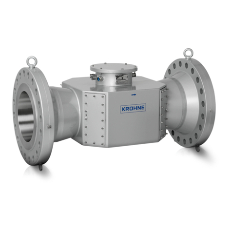
KROHNE ALTOSONIC 5 User manual

Ultrasonic liquid flowmeter for custody transfer
ALTOSONIC 5 Handbook
© KROHNE 12/2022 - 4004360704 - MA ALTOSONIC 5 en R05
All rights reserved. It is prohibited to reproduce this documentation, or any part thereof, without
the prior written authorisation of KROHNE Messtechnik GmbH.
Subject to change without notice.
2
ALTOSONIC 5
www.krohne.com 12/2022 - 4004360704 - MA ALTOSONIC 5 en R05
Copyright 2022 by
KROHNE Messtechnik GmbH - Ludwig-Krohne-Str. 5 - 47058 Duisburg (Germany)
: IMPRINT :::::::::::::::::::::::::::::::::::::::
CONTENTS
3
www.krohne.com12/2022 - 4004360704 - MA ALTOSONIC 5 en R05
ALTOSONIC 5
1 Safety instructions 6
1.1 Intended use ..................................................................................................................... 6
1.2 Certifications .................................................................................................................... 6
1.3 Safety instructions from the manufacturer ..................................................................... 7
1.3.1 Copyright and data protection ................................................................................................ 7
1.3.2 Disclaimer ............................................................................................................................... 8
1.3.3 Product liability and warranty ................................................................................................ 8
1.3.4 Information concerning the documentation........................................................................... 8
1.3.5 Warnings and symbols used................................................................................................... 9
1.3.6 Manufacturer ........................................................................................................................ 10
1.4 Safety instructions for the operator............................................................................... 10
2 Device description 11
2.1 Scope of delivery............................................................................................................. 11
2.2 General device description............................................................................................. 12
2.2.1 Flow sensor........................................................................................................................... 12
2.2.2 The signal converter ............................................................................................................. 13
2.2.3 Cable glands and cables....................................................................................................... 14
2.2.4 Monitoring, Configuration and Diagnostic tool..................................................................... 14
2.3 Explosion safety approval standards and markings...................................................... 15
2.3.1 Approvals .............................................................................................................................. 15
2.3.2 Standards .............................................................................................................................. 16
2.3.3 Flow sensor markings .......................................................................................................... 17
2.3.4 Signal converter markings ................................................................................................... 19
2.4 Nameplates .................................................................................................................... 20
3 Mechanical installation 22
3.1 Notes on installation ...................................................................................................... 22
3.2 Storage ........................................................................................................................... 22
3.3 Transport ........................................................................................................................ 23
3.4 Pre-installation requirements ....................................................................................... 23
3.5 Installation...................................................................................................................... 24
3.5.1 Electrostatic charge.............................................................................................................. 24
3.5.2 Mounting position.................................................................................................................. 24
3.5.3 Pipe diameters...................................................................................................................... 25
3.5.4 Flow conditioners.................................................................................................................. 25
3.5.5 Inlet and outlet...................................................................................................................... 25
3.5.6 Mounting position.................................................................................................................. 26
3.5.7 Support of the flow sensor.................................................................................................... 27
3.5.8 Flange deviation.................................................................................................................... 27
3.5.9 Special considerations.......................................................................................................... 28
3.5.10 Air venting ........................................................................................................................... 29
3.5.11 Pressure and temperature sensors ................................................................................... 29
3.6 Backpressure ................................................................................................................. 30
3.6.1 Open discharge ..................................................................................................................... 32
3.6.2 Control valve ......................................................................................................................... 32
3.6.3 Pump ..................................................................................................................................... 33
3.7 Meteorological conditions.............................................................................................. 33
CONTENTS
4 www.krohne.com 12/2022 - 4004360704 - MA ALTOSONIC 5 en R05
ALTOSONIC 5
4 Electrical installation 34
4.1 Safety instructions.......................................................................................................... 34
4.2 Overview of electrical installation.................................................................................. 35
4.3 Opening the covers......................................................................................................... 36
4.3.1 Flow sensor........................................................................................................................... 36
4.3.2 Signal converter.................................................................................................................... 36
4.4 How to use the cable glands .......................................................................................... 37
4.5 Flow sensor connections................................................................................................ 40
4.6 Signal converter connections......................................................................................... 42
4.6.1 Multiplexer board (MUX) connections .................................................................................. 43
4.6.2 Monitoring Configuration and Diagnostics (COM 1) board connections.............................. 44
4.6.3 Smart IO board (SMART IO) connections.............................................................................. 45
4.6.4 RS485 IO board (COM 2) connections ................................................................................... 53
4.6.5 Power Supply Unit (PSU) connections.................................................................................. 55
4.6.6 Digital Processor Board (DPB) connections ........................................................................ 56
4.6.7 Power Supply Unit Intrinsically Safe (PSU Ex) connections ................................................ 57
4.6.8 Analog Processor Board (APB) connections........................................................................ 57
4.7 Equipotential bonding..................................................................................................... 57
5 Start-up 58
5.1 Switching on the power .................................................................................................. 58
6 Operation 59
7 MCD tool 60
7.1 Introduction .................................................................................................................... 60
7.2 Installation of the software ............................................................................................ 60
7.3 Starting a session........................................................................................................... 60
7.4 Loading a monitoring configuration............................................................................... 65
7.5 Changing and saving a monitoring configuration.......................................................... 68
7.5.1 Creating a monitoring configuration .................................................................................... 68
7.5.2 Saving a monitoring configuration with a new name........................................................... 72
7.5.3 Saving a monitoring configuration with its current name ................................................... 73
7.6 Creating a monitoring configuration.............................................................................. 74
7.7 Viewing data.................................................................................................................... 77
7.7.1 Unformatted data.................................................................................................................. 78
7.8 Customizing the way data is presented ......................................................................... 79
7.8.1 Setting up tabs in the user view window .............................................................................. 79
7.8.2 Creating a new grid definition............................................................................................... 81
7.8.3 Creating a new graphical presentation ................................................................................ 85
7.9 Creating reports ............................................................................................................. 86
7.9.1 Reporting related to parameter settings ............................................................................. 87
7.9.2 Reporting related to process values .................................................................................... 91
7.9.3 Reporting related to calibration parameters ....................................................................... 91
7.9.4 Reporting related to privileges............................................................................................. 91
7.10 Remote logging............................................................................................................. 91
CONTENTS
5
www.krohne.com12/2022 - 4004360704 - MA ALTOSONIC 5 en R05
ALTOSONIC 5
7.11 On-device logging......................................................................................................... 92
7.11.1 Get logged data from flowmeter......................................................................................... 93
7.12 Customizing the data logging process......................................................................... 95
7.13 Adjusting parameter settings..................................................................................... 100
7.13.1 Adjusting meter factor ...................................................................................................... 100
7.14 Adjusting the external display settings...................................................................... 104
8 Service 108
8.1 Availability of services .................................................................................................. 108
8.2 Returning the device to the manufacturer................................................................... 108
8.2.1 Returning the device to the manufacturer ......................................................................... 108
8.2.2 Form (for copying) to accompany a returned device.......................................................... 109
8.3 Disposal ........................................................................................................................ 109
9 Technical data 110
9.1 Measuring principle...................................................................................................... 110
9.2 Transit time measuring principle ................................................................................ 110
9.3 Technical data table ..................................................................................................... 112
9.4 Dimensions and weights .............................................................................................. 119
9.5 Flow table ..................................................................................................................... 123
1 SAFETY INSTRUCTIONS
6
ALTOSONIC 5
www.krohne.com 12/2022 - 4004360704 - MA ALTOSONIC 5 en R05
1.1 Intended use
The ALTOSONIC 5 is a highly accurate flowmeter, intended for custody transfer, fiscal, allocation
and leak detection applications.
1.2 Certifications
This device fulfils the statutory requirements of the relevant directives.
For more information on the directives, standards and the approved certifications, please refer
to the declaration of conformity supplied with the device or downloadable from the
manufacturer’s website.
Other approvals and standards
•Custody transfer approvals according to:
Measurement Instrument Directive 2014/32/EU) /
UK Measuring Instrument Regulations 2016 No. 1153
OIML R117-1 (International Organization for Legal Metrology)
CAUTION!
Responsibility for the use of the measuring devices with regard to suitability, intended use and
corrosion resistance of the used materials against the measured fluid lies solely with the
operator.
INFORMATION!
The manufacturer is not liable for any damage resulting from improper use or use for other than
the intended purpose.
Product marking
Figure 1-1: Examples of marking logo
The manufacturer certifies successful testing of the product by applying the conformity mark on
the device.
SAFETY INSTRUCTIONS 1
7
ALTOSONIC 5
www.krohne.com12/2022 - 4004360704 - MA ALTOSONIC 5 en R05
North America:
•Certified for use in potentially explosive atmospheres according to DIV1 and Zone 1
classification.
•Custody transfer in compliance with API (American Petroleum Institute)
Canada:
•Certified for use in potentially explosive atmospheres according to DIV1 and Zone 1
classification.
•Custody transfer in compliance with Measurement Canada requirements.
•CRN (Canadian Registration Number)
Other standards:
•IECEx according to:
IEC 60079-0
IEC 60079-1
IEC 60079-11
1.3 Safety instructions from the manufacturer
1.3.1 Copyright and data protection
The contents of this document have been created with great care. Nevertheless, we provide no
guarantee that the contents are correct, complete or up-to-date.
The contents and works in this document are subject to copyright. Contributions from third
parties are identified as such. Reproduction, processing, dissemination and any type of use
beyond what is permitted under copyright requires written authorisation from the respective
author and/or the manufacturer.
The manufacturer tries always to observe the copyrights of others, and to draw on works created
in-house or works in the public domain.
The collection of personal data (such as names, street addresses or e-mail addresses) in the
manufacturer's documents is always on a voluntary basis whenever possible. Whenever
feasible, it is always possible to make use of the offerings and services without providing any
personal data.
We draw your attention to the fact that data transmission over the Internet (e.g. when
communicating by e-mail) may involve gaps in security. It is not possible to protect such data
completely against access by third parties.
We hereby expressly prohibit the use of the contact data published as part of our duty to publish
an imprint for the purpose of sending us any advertising or informational materials that we have
not expressly requested.
INFORMATION!
Not all country specific approvals are listed here. Please consult KROHNE in case of a specific
approval that is not listed here.
1 SAFETY INSTRUCTIONS
8
ALTOSONIC 5
www.krohne.com 12/2022 - 4004360704 - MA ALTOSONIC 5 en R05
1.3.2 Disclaimer
The manufacturer will not be liable for any damage of any kind by using its product, including,
but not limited to direct, indirect or incidental and consequential damages.
This disclaimer does not apply in case the manufacturer has acted on purpose or with gross
negligence. In the event any applicable law does not allow such limitations on implied warranties
or the exclusion of limitation of certain damages, you may, if such law applies to you, not be
subject to some or all of the above disclaimer, exclusions or limitations.
Any product purchased from the manufacturer is warranted in accordance with the relevant
product documentation and our Terms and Conditions of Sale.
The manufacturer reserves the right to alter the content of its documents, including this
disclaimer in any way, at any time, for any reason, without prior notification, and will not be liable
in any way for possible consequences of such changes.
1.3.3 Product liability and warranty
The operator shall bear responsibility for the suitability of the device for the specific purpose.
The manufacturer accepts no liability for the consequences of misuse by the operator.
Improper installation or operation of the devices (systems) will cause the warranty to be void.
The respective "Standard Terms and Conditions" which form the basis for the sales contract
shall also apply.
1.3.4 Information concerning the documentation
To prevent any injury to the user or damage to the device it is essential that you read the
information in this document and observe applicable national standards, safety requirements
and accident prevention regulations.
If this document is not in your native language and if you have any problems understanding the
text, we advise you to contact your local office for assistance. The manufacturer cannot accept
responsibility for any damage or injury caused by misunderstanding of the information in this
document.
This document is provided to help you establish operating conditions, which will permit safe and
efficient use of this device. Special considerations and precautions are also described in the
document, which appear in the form of icons as shown below.
SAFETY INSTRUCTIONS 1
9
ALTOSONIC 5
www.krohne.com12/2022 - 4004360704 - MA ALTOSONIC 5 en R05
1.3.5 Warnings and symbols used
Safety warnings are indicated by the following symbols.
• HANDLING
This symbol designates all instructions for actions to be carried out by the operator in the
specified sequence.
iRESULT
This symbol refers to all important consequences of the previous actions.
DANGER!
This warning refers to the immediate danger when working with electricity.
DANGER!
This warning refers to the immediate danger of burns caused by heat or hot surfaces.
DANGER!
This warning refers to the immediate danger when using this device in a hazardous atmosphere.
DANGER!
These warnings must be observed without fail. Even partial disregard of this warning can lead to
serious health problems and even death. There is also the risk of seriously damaging the device
or parts of the operator's plant.
WARNING!
Disregarding this safety warning, even if only in part, poses the risk of serious health problems.
There is also the risk of damaging the device or parts of the operator's plant.
CAUTION!
Disregarding these instructions can result in damage to the device or to parts of the operator's
plant.
INFORMATION!
These instructions contain important information for the handling of the device.
LEGAL NOTICE!
This note contains information on statutory directives and standards.
1 SAFETY INSTRUCTIONS
10
ALTOSONIC 5
www.krohne.com 12/2022 - 4004360704 - MA ALTOSONIC 5 en R05
1.3.6 Manufacturer
The instrument is developed and manufactured by:
KROHNE Altometer
Kerkeplaat 12
3313 LC Dordrecht
The Netherlands
For information, maintenance or service please contact your nearest local KROHNE
representative.
1.4 Safety instructions for the operator
DANGER!
•
Do not change the device. Unauthorised changes may affect the explosion safety of the
devices.
•
The prescriptions and regulations as well as the electrical data described in the EC type
examination certificate must be obeyed.
•
Beside the instructions for electrical installations in non-hazardous locations according to
the applicable national standard (equivalent to HD 384 or IEC 60364, e.g. VDE 0100),
especially the regulations in EN 60079-14 "Electrical installations in hazardous locations" or
equivalent national standard (e.g. DIN VDE 0165 Part 1) or dust hazardous areas such as EN
60079-14:2014 must be strictly followed.
•
Installation, establishment, utilization and maintenance are only allowed to be executed by
personnel with an education in explosion safety!
DEVICE DESCRIPTION 2
11
ALTOSONIC 5
www.krohne.com12/2022 - 4004360704 - MA ALTOSONIC 5 en R05
2.1 Scope of delivery
INFORMATION!
Do a check of the packing list to make sure that you have all the elements given in the order.
INFORMATION!
The instrument is delivered in a seaworthy, reinforced wooden crate. Inspect the packing
carefully for damages or signs of improper handling. Report damage to the carrier and to the
local office of the manufacturer.
Figure 2-1: Scope of delivery
1 Product documentation
2 CE declaration of conformity
3 Flow sensor(Stainless Steel or Carbon Steel)
4 Signal converter
5 Three signal cables, one PT100 cable
6 Inlet spool piece plus flow conditioner
CAUTION!
When multiple meters are delivered, check the serial number on each part so that each flow
sensor is accompanied by its own spool piece, flow conditioner and signal converter.
Serial number is S/N 123456789 1X1
where X = the type hardware, e.g. X = 0 for the flow sensor, X = 1 for the signal converter
etc.
INFORMATION!
Calibration reports and project specific documents are in the meter's data book that is sent
separately.
2 DEVICE DESCRIPTION
12
ALTOSONIC 5
www.krohne.com 12/2022 - 4004360704 - MA ALTOSONIC 5 en R05
2.2 General device description
The ALTOSONIC 5 flowmeter consists of a flow sensor and a signal converter.
2.2.1 Flow sensor
A series of ultrasonic transducers are installed in the measuring tube of the flow sensor. Each
pair of intrinsically safe ultrasonic transducers forms an acoustic measurement path. The
acoustic measurement path consists of one (direct) chord.
The chords in the horizontal plane are used for flow measurement, the chord in the vertical
plane is used for diagnostics only.
The transducers are electrically connected to the connection box on top of the flow sensor with
coaxial cables.
Acoustic signals are transmitted and received by means of ultrasonic transducers. The active
part of an ultrasonic transducer is a small disk of piezo electric ceramic in the front of the
transducer. It is packaged (sealed) in a construction of metal parts and installed behind a metal
acoustic window. The transducer itself is not exposed to the measured liquid. The window is
designed to achieve the best efficiency for transmitting and receiving ultrasound signal through
the liquid.
When servicing the transducers, no special retraction tool is used.
For the ALTOSONIC 5 Generation 1 flow sensor only the inner parts of the transducers need to be
replaced, therefor the complete transducer housing can stay pressurised. Normal toolbox pliers
to release inner parts for removal are used. However, to install a new transducer inner part a
special install tool is recommended and a specific service procedure should be followed. Note
that the meter should not be extremely cold or hot during such a replacement of inner parts.
For the ALTOSONIC 5 Generation 2 flow sensors the complete transducer can simply be
removed using Allen hex keys, but the pipe must be empty and depressurised. This should be
done by KROHNE personnel only.
Figure 2-2: Flow sensor
1 ALTOSONIC UFS-5 Generation 1
2 ALTOSONIC UFS-5 Generation 2
INFORMATION!
In this manual, the ALTOSONIC UFS-5 Generation 1 version is shown in most illustrations.
Please note that all information is applicable for the ALTOSONIC UFS-5 Generation 2 version too,
unless indicated.
DEVICE DESCRIPTION 2
13
ALTOSONIC 5
www.krohne.com12/2022 - 4004360704 - MA ALTOSONIC 5 en R05
2.2.2 The signal converter
Figure 2-3: Signal converter
Number Board name Function Short name
0 Power Supply Unit Power supply for all
cards in signal
converter
PSU
1 SMART IO Configurable IO SMART IO1
2 SMART IO (optional) Configurable IO SMART IO2
3 RS485 IO Board 4x RS485 Serial
communication port COM 2
4 Monitoring
Configuration and
Diagnostics
Logging and
communication COM 1
5 Digital Processor Board Calculation of flow rate DPB
6 Power Supply Unit
Intrinsically Safe Intrinsically safe power
supply PSU Ex
7 Multiplex Board Connection of the
analog signals
(transducers and body
temperature) from the
flow sensor to the APB
MUX
8 Ground (optional) No function GND
9 Analog Processor Board Processes the analog
signals from the flow
sensor
APB
INFORMATION!
Detailed descriptions and connections can be found in Chapter 4.
2 DEVICE DESCRIPTION
14
ALTOSONIC 5
www.krohne.com 12/2022 - 4004360704 - MA ALTOSONIC 5 en R05
2.2.3 Cable glands and cables
The flow sensor and signal converter are installed mostly in a hazardous area. To achieve
compliance with the certifications, it is mandatory that the flow sensor and the signal converter
are installed with the supplied cables, cable glands and blanking elements. If other cable glands
or blanking elements are used, then they must be similar with the removed ones. This means
that the cable glands and the blanking elements must be explosion proof (Ex d) approved with Ex
approval certificates and suitable for braided and armed cable.
2.2.4 Monitoring, Configuration and Diagnostic tool
The KROHNE flowmeter Monitoring, Configuration and Diagnostics Tool (MCD) is a software
package to support the application of the ALTOSONIC 5 flowmeters. It is designed for a PC with a
Windows operating system and can be downloaded from www.krohne.com.
Individual parameters are classified according to “roles” in order to define differentiated access
rights. Each “role” is associated with a “typical” user or operator having specific responsibilities
and/or duties. Users must be registered with a username and a password, when registered the
role of the user is also defined, and by consequence also the access rights of that user.
The following roles have been defined, listed in according to the rank in the hierarchy.
Roles and authorisation
Above mentioned roles can be authorised to multiple users with specific usernames and
passwords. Each specific user can be recognized and his actions are better recognized in the
internal loggings of the UFC5.
In addition to restrictions depending of the defined role of a user, a physical “overwrite disable”
contact with dipswitches protects the configuration parameters, please refer to
Digital
Processor Board (DPB) connections
on page 56. This disables any user from making
modifications to parameters that would influence the measured flow or volume value. This
prevents unintentional or unauthorised changes to the parameters and possibly invalidation of
the calibration.
LEGAL NOTICE!
The parameters are stored in a configuration file. Configuration parameters are password
protected in order to prevent unauthorised modification. Access in order to read, view and
inspect parameter values is restricted by the type of user.
Operator restricted to personnel acting on behalf of the owner/ operator of the meter (for day
to day operation), to the discretion of the owner/operator of the meter.
Supervisor restricted to personnel acting on behalf of the owner/operator of the meter
(administrator function), to the discretion of the owner/operator of the meter.
Service restricted to authorised service personnel, to the discretion of KROHNE.
Service2 restricted to authorised service personnel, to the discretion of KROHNE with time
based password access. The time based password can be requested from KROHNE.
Calibrator restricted to personnel acting on behalf of a legal calibration station.
Factory restricted to KROHNE factory employees, to implement factory settings in the
meter.
DEVICE DESCRIPTION 2
15
ALTOSONIC 5
www.krohne.com12/2022 - 4004360704 - MA ALTOSONIC 5 en R05
Normally the flowmeter is delivered as a calibrated instrument. Therefore the configuration
parameters are meter specific and cannot be changed. Other parameters such as IO parameters
on frequency outputs and communication are application specific and can be changed if needed.
Any change in configuration is logged with time/date/user/previous value. This information can
be retrieved afterwards for auditing and verification purposes.
2.3 Explosion safety approval standards and markings
The flowmeter consists of a flow sensor and a signal converter, that are designed to meet
explosion safety requirements based on:
•an intrinsically safe flow sensor
•an Ex d flameproof / explosion proof signal converter
2.3.1 Approvals
The device is manufactured according to the European Directive 2014/34/EU (ATEX), IEC Scheme
02, UK 2016 Regulations, NEC 500/505 and CEC. The flowmeter is approved for installation and
use in hazardous locations of Zone 1 and 2 respectively Division 1 according to the applicable
international, European, Canadian and American standards as listed in the next section. The
approval numbers are:
Flow sensor
•ATEX: FTZU 14 ATEX 0131X
•IECEx: IECEx FTZU 14.0020X
•DIVISION 1 (CA & USA): LR 1338-1
•ZONE 1 (CA & USA): LR 1338-1
•UKCA: CSAE 21UKEX2734X
Signal converter
•ATEX: FTZU 14 ATEX 0042X
•IECEx: IECEx FTZU 14.0029X
•DIVISION 1 (CA & USA): LR 1338-2
•ZONE 1 (CA & USA): LR 1338-2
•UKCA: CSAE 22UKEX1445X
2 DEVICE DESCRIPTION
16
ALTOSONIC 5
www.krohne.com 12/2022 - 4004360704 - MA ALTOSONIC 5 en R05
2.3.2 Standards
Flow sensor
The flow sensor is manufactured in accordance with:
•IEC/EN 60079-0
•IEC/EN 60079-11
•CSA C22.2 No. 60079-0
•CSA C22.2 No. 60079-11
•CSA C22.2 No. 94
•CSA C22.2 No. 157
•CSA C22.2 No. 61010-1-12
•ANSI/ISA 60079-0
•ANSI/ISA 60079-11
•NEMA 250
•ANSI/UL913
•ANSI/ISA 61010-1
The flow sensor is designed to be used for gas groups and temperature classes as listed in the
following overview and has an ingress protection rating of IP66 or NEMA Type 4X.
Signal converter
The signal converter is manufactured in accordance with:
•IEC/EN 60079-0
•IEC/EN 60079-1
•IEC/EN 60079-11
•CSA C22.2 No. 60079-0
•CSA C22.2 No. 60079-1
•CSA C22.2 No. 60079-11
•CSA C22.2 No. 30
•CSA C22.2 No. 94
•CSA C22.2 No. 157
•CSA C22.2 No. 61010-1-12
•ANSI/ISA 60079-0
•ANSI/ISA 60079-11
•NEMA 250
•ANSI/UL913
•ANSI/ISA 12.22.01-2009 (R2013)
•ANSI/ISA 61010-1-2012
It is designed to be used for gas group IIB or IIB+H2 (Group B for Division 1) and temperature
class T5.
DEVICE DESCRIPTION 2
17
ALTOSONIC 5
www.krohne.com12/2022 - 4004360704 - MA ALTOSONIC 5 en R05
2.3.3 Flow sensor markings
The flow sensor is certified according to the markings in the table below and has temperature
class T6...T2 and has an enclosure protection of IP66 or NEMA Type 4x.
Ex marking
Ambient temperature
Process temperature
The temperature limits apply under the following conditions:
•The instrument is installed and operated in accordance with the installation directions given
in the manual.
Flow sensor approval Marking
IECEx and UKCA Ex ia IIC T6…T2 Gb
ATEX II 2G Ex ia IIC T6…T2 Gb
DIV 1 Class I, DIV 1, Groups B, C, D, temp class T6…T2
Zone 1 (Canada) Ex ia IIB+H2 T6…T2 Gb
Zone 1 (USA) Class I, Zone 1, AEx ia IIB+H2 T6…T2 Gb
Version: Ambient temperature (Ta)
Flanged transducers (incl. HV) -40°C...+65°C
Welded transducers -55°C...+65°C
Version Name Process temperature (Tp)
Standard version UFS 5-R-Ex -40...+120°C
Low process temperature (LT) UFS 5-R-LT-Ex -200...+120°C
High process temperature (HT) UFS 5-R-HT-Ex -40...+250°C
High viscosity (HV) UFS 5-R-HV-Ex -40...+120°C
Temperature class Maximum process temperature [ºC] at Ta = 65ºC
Standard
version
LT version HT version HV version
T6 50 70 70 50
T5 85 85 85 85
T4 120 120 120 120
T3 - - 185 -
T2 - - 250 -
2 DEVICE DESCRIPTION
18
ALTOSONIC 5
www.krohne.com 12/2022 - 4004360704 - MA ALTOSONIC 5 en R05
Electrical data
The flow sensor contains the following intrinsic safety circuits:
Circuit Parameters
Transducer circuit between flow sensor and signal
converter Vmax/Ui = 18 V
Imax/Ii = 210 mA
Pi = 1 W
Li= 700 μH
Ci = 100 nF
PT100 circuit between flow sensor and signal
converter Vmax/Ui = 10 V
Imax/Ii = 25 mA
Pi = 250 mW
Li= 10 μH
Ci = 1 nF
DEVICE DESCRIPTION 2
19
ALTOSONIC 5
www.krohne.com12/2022 - 4004360704 - MA ALTOSONIC 5 en R05
2.3.4 Signal converter markings
The signal converter is certified according to the markings in the table below and has an
enclosure ingress protection of IP66 or NEMA Type 4x.
Ex marking
The converter housing is a flame proof/explosion proof enclosure and is available in two
variants.
Ambient temperature ATEX / IECEx / UKCA
Ambient temperature DIV 1 / Zone 1 (Canada / USA)
Electrical data
Signal converter approval Marking
ATEX II 2G Ex db [ia] IIB T5 Gb
II 2G Ex db [ia] IIB+H2 T5 Gb
IECEx and UKCA Ex db [ia] IIB T5 Gb
Ex db [ia] IIB+H2 T5 Gb
DIV 1 Class I, DIV 1, Groups B, C, D, temp class T5
Zone 1 (Canada) Ex d [ia] IIB+H2 T5 Gb
Zone 1 (USA) Class I, Zone 1, AEx d [ia] IIB+H2 T5 Gb
Version Ambient temperature group
IIB
Ambient temperature group
IIB + H2
Standard version -40...+65°C -40...+60°C
Low ambient temperature -55...+65°C -55...+60°C
Version Ambient temperature
Standard version -40...+65°C
Low ambient temperature -55...+65°C
Circuit Parameters
Power supply DC: 24 VDC +10%/-15%
AC: 100...240 VAC, 50/60 Hz
Power consumption DC: 28 W (with optional 24 VDC heater: 203 W)
AC: 35 W
Intrinsically safe multiplexer circuit of signal
converter Voc/Uo = 6.51 V
Isc/Io = 208 mA
Po = 0.34 W
Ca/Co= 22 μF (IIB) / 6 μF (IIB+H2)
La/Lo= 1.5 mH (IIB) / 500 μH (IIB+H2)
2 DEVICE DESCRIPTION
20
ALTOSONIC 5
www.krohne.com 12/2022 - 4004360704 - MA ALTOSONIC 5 en R05
2.4 Nameplates
Optional PT100 circuit between flow sensor and
signal converter Voc/Uo = 5.88 V
Isc/Io = 21 mA
Po = 31 mW
La/Lo = 100 mH
Ca/Co= 43 μF
Circuit Parameters
Figure 2-4: Example of an ATEX or IECEx nameplate on a sensor
Figure 2-5: Example of a UKCA nameplate on a sensor
Figure 2-6: Example of an ATEX or IECEx nameplate on a converter

Other KROHNE Measuring Instrument manuals

KROHNE OPTIFLEX 1100 C User manual

KROHNE

KROHNE OPTIFLEX 1100 C User manual

KROHNE FLEXMAG 4050 C User manual

KROHNE

KROHNE FLEXMAG 4050 C User manual

KROHNE ALTOSONIC V User manual

KROHNE

KROHNE ALTOSONIC V User manual

KROHNE OPTISWIRL 4200 Series Wiring diagram

KROHNE

KROHNE OPTISWIRL 4200 Series Wiring diagram

KROHNE OPTISONIC 8300 Wiring diagram

KROHNE

KROHNE OPTISONIC 8300 Wiring diagram

KROHNE DK32 Series Wiring diagram

KROHNE

KROHNE DK32 Series Wiring diagram

KROHNE OPTISWIRL 2100 User manual

KROHNE

KROHNE OPTISWIRL 2100 User manual

KROHNE OPTIMASS 1000 Series Instruction Manual

KROHNE

KROHNE OPTIMASS 1000 Series Instruction Manual

KROHNE OPTISWIRL 5080 Wiring diagram

KROHNE

KROHNE OPTISWIRL 5080 Wiring diagram

KROHNE OPTIFLUX 5000 User manual

KROHNE

KROHNE OPTIFLUX 5000 User manual

KROHNE OPTISWITCH 3300 C User manual

KROHNE

KROHNE OPTISWITCH 3300 C User manual

KROHNE OPTISWIRL 4200 User manual

KROHNE

KROHNE OPTISWIRL 4200 User manual

KROHNE DK32 Series Wiring diagram

KROHNE

KROHNE DK32 Series Wiring diagram

KROHNE IFC 090 User manual

KROHNE

KROHNE IFC 090 User manual

KROHNE OPTIWAVE 6300 C Instruction Manual

KROHNE

KROHNE OPTIWAVE 6300 C Instruction Manual

KROHNE ifc 300 Wiring diagram

KROHNE

KROHNE ifc 300 Wiring diagram

KROHNE OPTIFLEX 8200 C User manual

KROHNE

KROHNE OPTIFLEX 8200 C User manual

KROHNE CORIMASS MFM 4085 K/F User manual

KROHNE

KROHNE CORIMASS MFM 4085 K/F User manual

KROHNE OPTIWAVE-M 7400 C Supplement

KROHNE

KROHNE OPTIWAVE-M 7400 C Supplement

KROHNE ALTOSONIC UFM 610 P User manual

KROHNE

KROHNE ALTOSONIC UFM 610 P User manual

KROHNE OPTISONIC 8300 User manual

KROHNE

KROHNE OPTISONIC 8300 User manual

KROHNE DWM 2000 D User manual

KROHNE

KROHNE DWM 2000 D User manual

KROHNE OPTISWIRL 4070 Wiring diagram

KROHNE

KROHNE OPTISWIRL 4070 Wiring diagram

KROHNE 4000 Series User manual

KROHNE

KROHNE 4000 Series User manual

Popular Measuring Instrument manuals by other brands

Promax HD Ranger + user manual

Promax

Promax HD Ranger + user manual

Kyoritsu Electrical Instruments Works, Ltd. KEW6315-03 instruction manual

Kyoritsu Electrical Instruments Works, Ltd.

Kyoritsu Electrical Instruments Works, Ltd. KEW6315-03 instruction manual

Kyoritsu Electrical Instruments Works, Ltd. KEW 2062 instruction manual

Kyoritsu Electrical Instruments Works, Ltd.

Kyoritsu Electrical Instruments Works, Ltd. KEW 2062 instruction manual

Pro's Kit MT-3105 user manual

Pro's Kit

Pro's Kit MT-3105 user manual

Ono Sokki HT-3200 instruction manual

Ono Sokki

Ono Sokki HT-3200 instruction manual

red lion PAXLI Data Sheet / Manual

red lion

red lion PAXLI Data Sheet / Manual

Aqualytic SensoDirect CD 19 operating instructions

Aqualytic

Aqualytic SensoDirect CD 19 operating instructions

Alarmcom Aeon Labs HEM installation guide

Alarmcom

Alarmcom Aeon Labs HEM installation guide

AirPro AP500 Operation user's manual

AirPro

AirPro AP500 Operation user's manual

Challenger Optics CO-OTDR-CWDM-10M Series user guide

Challenger Optics

Challenger Optics CO-OTDR-CWDM-10M Series user guide

Powerline A3 instruction manual

Powerline

Powerline A3 instruction manual

Kyoritsu Electrical Instruments Works, Ltd. 6300 instruction manual

Kyoritsu Electrical Instruments Works, Ltd.

Kyoritsu Electrical Instruments Works, Ltd. 6300 instruction manual

J.P. SELECTA VR 2000 manual

J.P. SELECTA

J.P. SELECTA VR 2000 manual

Lake Shore 475 user manual

Lake Shore

Lake Shore 475 user manual

In-situ RuggedReader Operator's manual

In-situ

In-situ RuggedReader Operator's manual

Unit UTE9802+ user manual

Unit

Unit UTE9802+ user manual

Challenger Optics CO-OLS-MPO12U operating manual

Challenger Optics

Challenger Optics CO-OLS-MPO12U operating manual

ATO Digital Hydrometer Operation manual

ATO

ATO Digital Hydrometer Operation manual

manuals.online logo
manuals.online logoBrands
  • About & Mission
  • Contact us
  • Privacy Policy
  • Terms and Conditions

Copyright 2025 Manuals.Online. All Rights Reserved.