Kongskilde KPC 80 User manual

KPC 80 - 200
Dual strip cutters
Manual
Betriebsanleitung
Manuel de service
Instrucciones de funcionamiento
Podręcznik użytkownika
Brugsanvisning
2
GB
This user manual applies to the Kongskilde guillotine
cutter model KPC 80-200.
Description:
The KPC cutter is designed for cutting down trims of
plastic foils, paper and cardboard.
The maximum thickness of plastic foils is 300 µm, while
the maximum thickness of paper and cardboard is 800
g/m2.
The cutter is designed for mounting in an enclosed pipe
system, that is, with a pipeline mounted both at the inlet
and outlet.
The cutter is designed to work with continuous vacuum
and has no pressure loss on the suction side when it is
cutting. The cutter is built to be an alternative to rotating
cutters that cuts the material into small pieces, gener-
ates a lot of dust and has a high noise level. With the
KPC cutter, the waste can be cut into longer strips, so
it is possible to bale. Furthermore, the reduced number
of cuts makes the dust created by the cutter extremely
low.
Only use the KPC cutter for cutting the materials it is
designed for, due to risk of knife destruction or damage.
Warning notes:
Avoid accidents by always following the safety instruc-
tions given in the user manual and on the safety signs
located on the cutter.
The cutter must be installed in a closed duct system,
without access to moving parts..
Any foreign objects allowed into the system, intentional-
ly or unintentionally, may eventually damage the cutter.
Lack of supervision of the cutter can result in wear
and/or damage to vital parts, see section "Service and
maintenance".
Ensure that both inlet/outlet pipes are intact and prop-
erly secured during operation.
Always disconnect electricity and compressed air to the
cutter prior to repair and maintenance.
Never do any dismounting or service to the cutting
device before disconnecting the power plug and com-
pressed air.
Never put your hand into the cutter inlet or outlet during
operation.
The cutter should be mounted in an accessible location
for maintenance. The working area around the cutter
should be clear and trip free when carrying out main-
tenance. Use gloves when working with the knifes, the
edges are sharp.
Make sure that there is adequate lighting when working
on the cutter.
In cases where is it necessary to remove material
blocking the moveable knife, compressed air and elec-
tricity must always be switched off to prevent start up
of the cutter. If removal of material in the cutter is done
while the power / air is switched on, the cutter will start
as soon as the blocking material is removed. This in-
volves great risk of personal injuries!
In case of abnormal vibrations or noise, stop the cutter
immediately and examine the cause. In case of doubt,
skilled assistance must be called in for repair and main-
tenance.
Take care that the cutter is securely installed, onto a
stable surface, a to avoid unintensional movement of
the cutter.
To avoid any unintentional contact with the moving
knife, pipes of minimum 850 mm length, with a diam-
eter of maximum Ø 200 mm must be installed onto the
inlet and outlet connections.
These pipes must be installed with bolt clamps, where
tools are necessary for dismantling.
In case it is not possible to use minimum 850 mm
tubes, it must be insured that there within minimum
850 mm from the separator are used bolt clamps,
where tools are necessary for dismantling.
The reason for this is, that according to EU-directive
2006/42/EC (Machinery Directive), it is not allowed for
any unauthorized personnel to gain access to rotating
parts. In case quick couplings are used, unautorized
personnel could dismantle the tubing, and have access
to the cutting knife.
Warning signs:
Warning signs with symbols without text are found on
the cutter. The symbols are explained below.
Read the user manual carefully and
observe the warning texts in the user
manual and on the cutter.
3
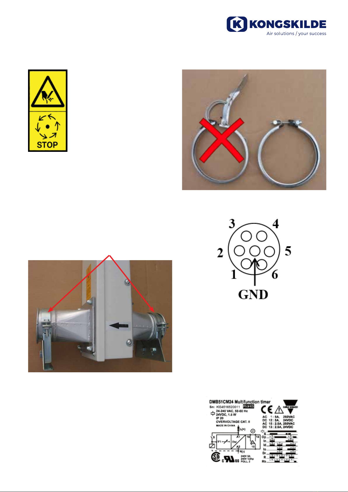
Inlet, outlet or other guards must not
be opened or removed while the cutter
is in operation.
Mounting:
The cutter must always be installed with minimum 850
mm straight pipe on each side of the cutter, so nobody
can reach the cutting device with a hand. Use the en-
closed clear acrylic 1 meter pipe on the exit side. The
operator can then physically se that the cutter is work-
ing correctly.
When placing the cutting device, make sure that the air
ow direction is correct. See the arrow on the cutter´s
enclosure.
The cutter can be xed by using 2 pcs. pipe support,
one on each side of the cutter.
The cutting device can be xed to any stabile layer,
hanging or standing, in any angle, from horizontal to
vertical.
Always use bolt clamps and not quick release clamps
for connecting the cutter with the pipe system.
Electrical installation:
Pin 1 - Solenoid signal
Pin 2 - 24VDC solenoid
GND - Timer box green-yellow connector
Connection:
The power can be taken from the machine, so the cut-
ter is in operation only when the machine is running.
Con A1 24VDC+ (machine run signal)
Con A2 24VDC-
Con 15 24VDC+
Con 18 PIN 1 in connector plug for cutter

4
Timer settings:
Function mode is set on Rb
Examples:
8 sec cut 15 sec cut
Time setting 8 2,5
Time range 1 sec 6 sec
Electrical diagram:
Service and maintenance:
For your safety, read the safety instructions before
you work on the device.
Maintenance
In general there is no frequently maintenance, such as
greasing and oiling.
Cleaning
Cleaning of the cutting devices is needed from time to
time, depending of the type of material that is running.
Exchanging or turning knifes
1. Release air pressure (A)
Disconnect air pipe (B)
Disconnect power plug (C)
A
B
C

5
2. Remove the 4 screws on the lower knife.
Turn it 180º or replace it.
Before the knife is tted, both the knife and the
base must be 100% clean. Use cleaning liquid
like petroleum or similar.
Then attach the knife.
3. Use the same procedure for the upper knife.
4. Turn the cutting device. Use the same proce
dure for the center knife.
This can’t be rotated as its using both sides.
5. Test the cutting device before placing it back in
the box on the pipe system.
Free play on knifes
There can be two reasons for adjusting the distance on
the strip cutter:
1. Material is not cut correctly and material is forced
in between the blades and the middle knife is not
moving up and down. Before making any adjust-
ments, please make sure that the knifes are still
sharp and don’t have any marks on the knife edge.
In this case we will have to make less distance be-
tween the body and the guide rail holders. Typically
0,02mm.
2. Dust can build up in the bushings, so there is no
tolerance in between the bushing and the rail. The
knifes will then go to hard against each other and it
can’t be moved back by the force of the air cylinder.
In this case we will have to make more distance be-
tween the body and the guide rail holders. Typically
0,03mm.
When adjusting the distance you must always start in
the side where the knife touches rst (pos. 1 or 3).
Then test the cutter and see if this is enough or modi-
cation in the other side is necessary (pos. 2 or 4).
12
34

6
Insert or remove precision steel
Loosen the screw in the corner where you want to
modify.
All cutters has precision steel in all 4 points, so when
you add, make sure that the inserted piece is on top of
what’s already inserted (not always one piece).
!! Before testing make sure that all bolts and screws are
tightened.
For distance adjustment use precision steel band:
The steel precision steel band can be purchased in
most professional tool shops.

7
EC Declaration of Conformity
Kongskilde Industries A/S, DK-4180 Sorø - Denmark, hereby declares that:
Kongskilde cutters type KPC 80 - 200
Are produced in conformity with the following EC-directives:
• Machinery Directive 2006/42/EC
• Electro Magnetic Compatibility Directive 2014/30/EC
• Low Voltage Directive 2014/35/EC
Furthermore, all electric components used are UL listed to comply with US standards.
Kongskilde Industries A/S
Sorø 01.07.2016
Mogens Rüdiger
CEO

Kongskilde Industries A/S
Skælskørvej 64
DK - 4180 Sorø
Tel. +45 72 17 60 00
www.kongskilde-industries.com
121 116 344 You can always nd the latest version of the manuals at 20.01.2020
www.kongskilde-industries.com
This manual suits for next models
1
Table of contents
Other Kongskilde Cutter manuals


Popular Cutter manuals by other brands

Milwaukee
Milwaukee HEAVY DUTY M12 FCOT Original instructions

SignWarehouse.com
SignWarehouse.com Bobcat BA-60 user manual

Makita
Makita 4112HS instruction manual

GEISMAR STUMEC
GEISMAR STUMEC MTZ 350S manual

Hitachi
Hitachi CM 4SB2 Safety instructions and instruction manual

Dexter Laundry
Dexter Laundry 800ETC1-20030.1 instruction manual


