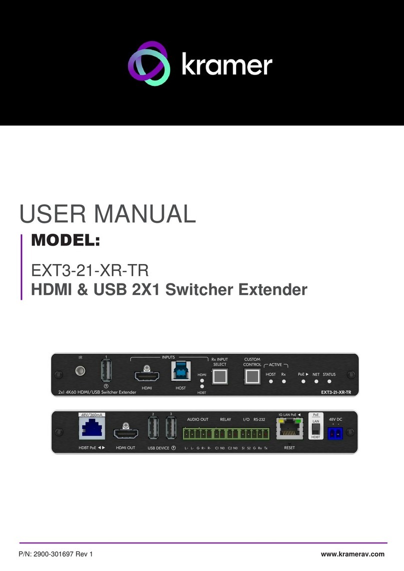
Kramer EXT3-C-XR-TR User manual

Kramer Electronics Ltd.
EXT3-21-XR-TR –Contents
i
Contents
Introduction 1
Getting Started 1
Overview 2
Typical Applications 4
Defining EXT3-21-XR-TR HDMI & USB 2X1 Switcher Extender 5
Mounting EXT3-21-XR-TR 8
Connecting EXT3-21-XR-TR 9
Connecting to EXT3-21-XR-TR via RS-232 11
Operating and Controlling EXT3-21-XR-TR 12
Principles of Operation 12
Using Front and Rear Panel Buttons 16
Operating via Ethernet 17
Using Embedded Web Pages 20
Routing Operations 23
Setting AV Properties 27
Device Settings and Maintenance 30
Setting Control Gateway Properties 39
Diagnostics 54
Administration 55
Viewing the About Page 60
Upgrading Firmware 61
Technical Specifications 62
Default Communication Parameters 64
Protocol 3000 65
Understanding Protocol 3000 65
Protocol 3000 Commands 66
Result and Error Codes 80

Kramer Electronics Ltd.
EXT3-21-XR-TR –Introduction
1
Introduction
Welcome to Kramer Electronics! Since 1981, Kramer Electronics has been providing a world
of unique, creative, and affordable solutions to the vast range of problems that confront the
video, audio, presentation, and broadcasting professional on a daily basis. In recent years, we
have redesigned and upgraded most of our line, making the best even better!
Getting Started
We recommend that you:
•Unpack the equipment carefully and save the original box and packaging materials for
possible future shipment.
•Review the contents of this user manual.
Go to www.kramerav.com/downloads/EXT3-21-XR-TR to check for up-to-date user
manuals, application programs, and to check if firmware upgrades are available (where
appropriate).
Achieving Best Performance
•Use only good quality connection cables (we recommend Kramer high-performance,
high-resolution cables) to avoid interference, deterioration in signal quality due to poor
matching, and elevated noise levels (often associated with low quality cables).
•Do not secure the cables in tight bundles or roll the slack into tight coils.
•Avoid interference from neighboring electrical appliances that may adversely influence
signal quality.
•Position your Kramer EXT3-21-XR-TR away from moisture, excessive sunlight and dust.
Safety Instructions
Caution:
•This equipment is to be used only inside a building. It may only be connected to other
equipment that is installed inside a building.
•For products with relay terminals and GPI\O ports, please refer to the permitted rating
for an external connection, located next to the terminal or in the User Manual.
•There are no operator serviceable parts inside the unit.
Warning:
•Use only the power cord that is supplied with the unit.
•To ensure continuous risk protection, replace fuses only according to the rating
specified on the product label which is located on the bottom of the unit.

Kramer Electronics Ltd.
EXT3-21-XR-TR –Introduction
2
Recycling Kramer Products
The Waste Electrical and Electronic Equipment (WEEE) Directive 2002/96/EC aims to reduce
the amount of WEEE sent for disposal to landfill or incineration by requiring it to be collected
and recycled. To comply with the WEEE Directive, Kramer Electronics has made
arrangements with the European Advanced Recycling Network (EARN) and will cover any
costs of treatment, recycling and recovery of waste Kramer Electronics branded equipment on
arrival at the EARN facility. For details of Kramer’s recycling arrangements in your particular
country go to our recycling pages at www.kramerav.com/il/quality/environment.
Overview
EXT3-21-XR-TR is a high−performance, extended−reach HDBaseT 3.0 extender for 4K60Hz
(4:4:4) HDMI, USB, Ethernet, PoE power, RS−232, and IR signals over twisted pair, flexibly
set as transmitter−side or receiver−side device.
EXT3-21-XR-TR transmitter−side converts all input signals into the transmitted HDBaseT 3.0
signal and extends uncompressed video signals to up 100m (330ft) over CAT copper cables
at up to 4K@60Hz (4:4:4) video resolution.
EXT3-21-XR-TR receiver−side is an auto−switcher with HDMI and HDBaseT inputs that
receives the HDBaseT 3.0 signal and converts it back into the original input signals. The
connected USB 3.1 peripherals, such as a room camera and microphone, are switchable for
use of the active USB host, for convenient hybrid meeting operation with both room and
online participants.
EXT3-21-XR-TR provides exceptional quality, advanced and user-friendly operation, and
flexible control.
Exceptional Quality
•HDMI Signal Switching and Extension –HDCP 2.3, EDID and CEC signals are passed
through from the source to the display. Supports HDR10, deep color, x.v.Color™, lip
sync, HDMI uncompressed audio channels, Dolby TrueHD, DTS–HD, 2K, 4K, and 3D as
specified in HDMI 2.0.
•Flexible USB Switching and Extension–An active USB 3.1 host is connected to the
extender at either the transmitter or receiver sides. USB 2.0 signals are extended
between the extender transmitter and receiver sides, and switched at the receiver side,
enabling connection of the active USB host to both local and remote USB devices, such
as camera and audio devices, or HID (Human Interface Devices) mouse or keyboard
devices.
•Multi–channel Audio Transmission - Up to 32 channels of digital stereo uncompressed
signals for supporting studio–grade surround sound.
•Ethernet Extension - Ethernet interface data flows in both directions, allowing extension
of up to 1 Gbps Ethernet connectivity for LAN communication and device control.

Kramer Electronics Ltd.
EXT3-21-XR-TR –Introduction
3
Advanced and User-friendly Operation
•Hybrid-meeting Collaborative Switching–Controllable coupled−signals switching of both
AV and USB host inputs, for concurrent connection with AV output and room USB
devices, allows collaborative hybrid meeting where multiple meeting participants are
switched to share their content with both room and online meeting participants.
•Auto Switcher Ease of Use –Automatically plays signal of the plugged source on the
connected display, according to user-configured preferences, such as last-connected
input.
•Simple and Flexible Control –Remote IP-controller connection, browser operation
webpage, local panel buttons, or remotely connected contact-closure buttons, for easy
and fully flexible USB host ports selection, and switcher control.
•Convenient Power On/Off Control of Display - Simply press the DISPLAY ON button to
toggle on and off the power of the connected display using the configurable control
interface and commands, and view display power on/off status at all times via button
LED indication.
•Simple Control - Remote IP−controller connection, browser operation webpage, local
panel buttons, or remotely connected contact−closure buttons, for easy and fully flexible
user ports selection, signals routing, and switcher extender control.
Flexible Connectivity
•High Performance Standard Extender - Professional HDBaseT extender for providing
extended–reach signals over twisted–pair copper infrastructures. EXT3–21−XR–TR is a
standard extender that can be connected to any market–available HDBaseT–compliant
extension product. For optimum extension reach and performance, use recommended
Kramer cables.
•HDMI Mirroring - Transmitter–side extender mirrors input HDMI signal to loop output port
for connecting a local monitor or an additional unit in a daisy chain.
•Built-in Intelligent Control Gateway –Remote IP−driven intelligent control of connected
AV, USB, motorized projector screen and sensor devices via CEC, RS−232, IR, I/O or
Relay. Eliminating the need for an external control gateway, this feature reduces
installation complexity and costs, to enable easy integration with control systems, such
as Kramer Control.
•Audio De-embedding - The digital audio signal passing through to the output, is
de−embedded, converted to an analog signal and sent to the stereo balanced analog
audio output. This enables playing the audio on a locally connected professional audio
system (such as DSP) and speakers, in parallel to playing it on the speakers connected
to the AV acceptor device (such as TVs with speakers).
•Bidirectional RS–232 Extension- Serial interface data flows in both directions, allowing
data transmission and device control.
•Bidirectional Infrared Extension - interface data flows in both directions, allowing remote
control of peripheral devices located at either end of the extended line.
•Secured Operation —Standard IT−grade 802.1x authentication for secured IT LAN
connectivity operation.

Kramer Electronics Ltd.
EXT3-21-XR-TR –Introduction
4
•Cost–effective Maintenance - Status LED indicators for HDMI, Loop, HDBT, and USB
active host ports, facilitate easy local maintenance and troubleshooting.
•Comprehensive and Cost–effective Management –Local panel status LED, remote
IP−driven firmware upgrade and management via user−friendly embedded web pages,
and remote IP or local serial service and management via API commands and
responses communication, for flexible service options and ensure lasting, field proven
deployment.
•Easy and Elegant Installation —PoE powering via LAN port connection, or bidirectional
PoE powering via HDBaseT port connection, and MegaTOOLS™fan–less enclosure for
dropped–ceiling mounting, on or under table, or side–by–side mounting of 2 units in a
1U rack space with the recommended rack adapter, for easy switcher extender
deployment.
Typical Applications
EXT3-21-XR-TR is ideal for the following typical applications:
•Advanced switcher extender building-block for enterprise and education hybrid solutions.
•Upgrading deployed room solutions to hybrid-capable, controllable, and managed
solutions.
Controlling your EXT3-21-XR-TR
Control your EXT3-21-XR-TR directly via the front panel push buttons, remote GPIO buttons
or:
•Via the IP commands transmitted by a controller and touch screen system, or a browser
using built-in user-friendly Web pages.
•By RS-232 serial commands transmitted by a touch screen system, PC, or a serial
controller.

Kramer Electronics Ltd.
EXT3-21-XR-TR –Defining EXT3-21-XR-TR HDMI & USB 2X1 Switcher Extender
5
Defining EXT3-21-XR-TR HDMI &
USB 2X1 Switcher Extender
This section defines EXT3-21-XR-TR.
Configuring the device as transmitter (Tx) or receiver (Rx, default) is done via the front panel
button or the embedded webpages settings (see Setting Extender Operation Modes
on page 33).
Figure 1: EXT3-21-XR-TR HDMI & USB 2X1 Switcher Extender Front Panel
#
Feature
Function
IR 3.5mm Mini Jack Connector
Connect to an external IR emitter to control a local IR-controlled device
from the remote extender (for example, EXT3-21-XR-TR).
Connect to an IR sensor to control a remote IR-controlled device connected
to the remote extender side (for example, EXT3-21-XR-TR).
USB-A 3.1
Connect to a USB local peripheral device (for example, a USB camera, a
soundbar, microphone and so on).
HDMI IN Connector
Connect to an HDMI source.
USB-B 3.1 HOST Connector
Connect to a USB host (for example, a laptop) to communicate with the
USB peripheral devices (for example, a smart board) connected to USB
device ports on either the transmitter or the receiver sides of the extender.
HDMI and HDBT LEDs
Each input LED, lights green when a source is selected and active, blue
when a source is selected but not active, and Off when a source is not
selected.
Note: On transmitter mode, HDBT LED is always Off.
Rx INPUT SELECT Button
Press to select an input.
Press and hold for a minimum of 10 seconds to switch between Rx↔Tx
mode.
Switching between modes initiates Factory Reset.
DISPLAY ON Button
Press to toggle turning the display on and off.
Button LED lights ON after sending a DISPLAY ON message.
Button LED lights OFF after sending a DISPLAY OFF message.
ACTIVE HOST LED
Lights orange when local USB host is active.
ACTIVE Rx LED
Lights blue on active receiver mode.
PoE ►LED
Lights green when the device provides PoE to a connected device.
NET LED
Indicates networking status:
LED Color
Indicates
Dark
No IP address acquired.
Lights green
A valid IP address has been acquired.
Flashes green for 60s
A means to identify the device in a system.
Flashes red/green
IP fallback address has been acquired.
1
2
3
4
5
6
7
8
9
10
11

Kramer Electronics Ltd.
EXT3-21-XR-TR –Defining EXT3-21-XR-TR HDMI & USB 2X1 Switcher Extender
6
#
Feature
Function
STATUS
Indicates device status:
LED Color
Indicates
Off (Dark)
Device is powered and no active source
connected.
Blue
Device is powered, and an active source is
connected.
Green
Device is powered, an active source and acceptor
are connected.
12

Kramer Electronics Ltd.
EXT3-21-XR-TR –Defining EXT3-21-XR-TR HDMI & USB 2X1 Switcher Extender
7
Figure 2: EXT3-21-XR-TR HDMI & USB 2X1 Switcher ExtenderRear Panel
#
Feature
Function
HDBT PoE RJ-45 Connector
Connect to the HDBT RJ-45 connector on a paired receiver/transmitter
device (for example, a second EXT3-21-XR-TR device) that receives or
provides PoE.
Note: HDBT provides PoE only when the device is PSU-powered.
HDMI OUT Connector
Transmitter Mode: Connect to a local HDMI acceptor (for example, a
preview monitor).
Receiver Mode: Connect to an HDMI acceptor.
USB-A 3.1 (2 & 3) Connectors
Connect to the USB local peripheral devices (for example, a USB camera,
a soundbar, microphone and so on).
AUDIO OUT 5-pin Terminal Block
Connector
Connect to a balanced stereo analog audio acceptor.
RELAY (1& 2) on a 4-pin
Terminal Block Connector
Connect to relay-controlled devices (for example, a projector screen).
I/O (1 & 2) on a 3-pin Terminal
Block Connector (GND is
common for I/O and RS-232).
Connect the general input and output ports to connect to I/O-controlled
devices (for example, a sensor).
RS-232 3-pin Terminal Block
Connector
Connect to a serial-controlled device (for example, a projector).
1G LAN PoE RJ-45 Connector
Connect to a PC via a LAN. Receives Power (when PoE powered).
RESET Recessed Button
For restoring factory default settings, press the RESET button and connect
power to device (keep pressing longer than 6sec after power connection)
Set to Receiver mode by default.
PoE LAN/HDBT Selection Switch
Select the PoE providing source, either the LAN (default) or the HDBT port.
48V DC Power Connector
Connect to the power supply (when not PoE powered).
13
14
15
16
17
18
19
20
21
22
23

Kramer Electronics Ltd.
EXT3-21-XR-TR –Mounting EXT3-21-XR-TR
8
Mounting EXT3-21-XR-TR
This section provides instructions for mounting EXT3-21-XR-TR. Before installing, verify that
the environment is within the recommended range:
•Operation temperature –0to 40C (32 to 104F).
•Storage temperature –-40to +70C (-40 to +158F).
•Humidity –10% to 90%, RHL non-condensing.
Caution:
•Mount EXT3-21-XR-TR before connecting any cables or power.
Warning:
•Ensure that the environment (e.g., maximum ambient temperature & air flow) is
compatible for the device.
•Avoid uneven mechanical loading.
•Appropriate consideration of equipment nameplate ratings should be used for avoiding
overloading of the circuits.
•Reliable earthing of rack-mounted equipment should be maintained.
•Maximum mounting height for the device is 2 meters.
Mount EXT3-21-XR-TR in a rack:
•Use the recommended rack adapter
(see www.kramerav.com/product/EXT3-21-XR-TR).
Mount EXT3-21-XR-TR on a surface using one of the following
methods:
•Attach the rubber feet and place the unit on a flat surface.
•Fasten a bracket (included) on each side of the unit and attach it to
a flat surface. For more information go to
www.kramerav.com/downloads/EXT3-21-XR-TR.

Kramer Electronics Ltd.
EXT3-21-XR-TR –Connecting EXT3-21-XR-TR
9
Connecting EXT3-21-XR-TR
Always switch off the power to each device before connecting it to your EXT3-21-XR-TR.
After connecting your EXT3-21-XR-TR, connect its power and then switch on the power to
each device.
Figure 3: Connecting to the EXT3-21-XR-TR Rear Panels
To connect EXT3-C-XR-T to EXT3-21-XR-TR as illustrated in the example in Figure 3:
1. Connect the HDBT OUT port on the EXT3-21-XR-TR transmitter to the HDBT PoE port
on the EXT3-21-XR-TR receiver side.
2. On the EXT3-C-XR-T transmitter:
•Connect a USB-C source (for example, a laptop that supports Display Port Alternate
Mode) to the USB-C IN connector.
•Connect an HDMI LOOP connector to an HDMI acceptor.
3. On the EXT3-21-XR-TR receiver side:
▪Connect the HDMI OUT connector to an HDMI acceptor (for example, a
projector).
▪Connect the HDMI IN connector and HOST USB-B 3.1 port to an input source
(for example, a room PC).
4. Connect the USB DEVICE ports:
▪On the transmitter side, ports to USB devices (for example, the room microphone,
mouse, and keyboard).
▪On the receiver side, ports , to USB devices (for example, a smart board,
soundbar and PTZ camera).
USB devices can be connected to both the transmitter and receiver sides, as
necessary.
13
14
3
4
15

Kramer Electronics Ltd.
EXT3-21-XR-TR –Connecting EXT3-21-XR-TR
10
5. To control the projector via IR, connect the following:
▪On the EXT3-C-XR-T transmitter, connect an IR sensor cable to the IR 3.5mm mini
jack.
▪On the EXT3-21-XR-TR receiver side, connect the IR 3.5mm mini jack to an IR
emitter cable and attach the cable emitter side to the IR sensor of the projector.
Point the projector IR remote control to the IR sensor to pass an IR command via HDBT
to the projector.
6. To control the room devices via Ethernet, connect the following:
▪On the EXT3-C-XR-T transmitter LAN port, connect a touch panel designed to
operate Kramer Control (for example, KT-208).
▪On EXT3-21-XR-TR receiver side connect the 1G LAN PoE port to LAN.
▪Send IP commands via the LAN-connected room controller (for example SL-240C) to
control via LAN the Room PC, Active speakers, Projector screen, Occupancy
detector etc.
7. To serially control the PTZ camera, connect the following:
▪On EXT3-21-XR-TR receiver side connect the RS-232 port to the PTZ camera.
▪Send serial commands from LAN-connected SL-240C controller to the camera via
extender control gateway.
8. Connect the EXT3-21-XR-TR to power source(s), as follows:
▪Switch up the PoE power selector to LAN position and connect the 1G LAN PoE
port to a PoE-providing LAN switch.
▪Connect the power adapter to the power connector and to the mains electricity.
▪Switch down the PoE power selector to HDBT position and receive / provide PoE
via the HDBT.
To provide PoE power over the HDBT to the device that is connected to the HDBT port, you
need to use a power adapter for powering the EXT3-21-XR-TR.
1
20
19
22
20
23
22

Kramer Electronics Ltd.
EXT3-21-XR-TR –Connecting EXT3-21-XR-TR
11
Connecting to EXT3-21-XR-TR via RS-232
You can connect to EXT3-21-XR-TR via an RS-232 connection using, for example, a PTZ
camera, PC, or display.
EXT3-21-XR-TR features an RS-232 3-pin terminal block connector allowing the RS-232 to
control either the EXT3-21-XR-TR or a serially controllable device.
Connect the RS-232 terminal block on the rear panel of EXT3-21-XR-TR to a PC/controller,
as follows:
From the RS-232 9-pin D-sub serial port connect:
•Pin 2 to the TX pin on the EXT3-21-XR-TR RS-232
terminal block
•Pin 3 to the RX pin on the EXT3-21-XR-TR RS-232
terminal block
•Pin 5 to the G pin on the EXT3-21-XR-TR RS-232 terminal
block
RS-232 Device
EXT3-21-XR-TR

Kramer Electronics Ltd.
EXT3-21-XR-TR –Operating and Controlling EXT3-21-XR-TR
12
Operating and Controlling
EXT3-21-XR-TR
Principles of Operation
•Pair-synched Coupled AV+USB Auto Switching on page 12.
•Coupled or Individual AV+USB Switching on page 14.
•Flexible EXT3-21-XR-TR Auto Switching Policy on page 15.
•Online Meeting Systems Integration on page 15.
•Routing IP-Driven Control Signals via Built-in Control Gateway on page 15.Flexible
Remote Buttons Control on page 16.
•EXT3-21-XR-TR Flexible Powering on page 16.
•Single Device Operates as Either Tx or Rx on page 16.
Pair-synched Coupled AV+USB Auto Switching
Two paired EXT3-21-XR-TR devices, one set as a transmitter (Tx mode) and the other set as
a receiver (Rx mode), feature a default inter-synched pairing operation; No additional control
system is needed to synch the pairing operation. This kit-like pair operation provides a cost-
effective solution for standard rooms with flexible support for both Room-Based Meeting
(RBM) or Bring Your Own Meeting (BYOM) hybrid meeting scenarios, as follows:
RBM scenario:
•Rx-connected room PC/NUC is running the room-based meeting app, such as Zoom
Room.
•The room PC/NUC is auto-connected to all room USB devices, both the Tx-connected
and Rx-connected USB devices.

Kramer Electronics Ltd.
EXT3-21-XR-TR –Operating and Controlling EXT3-21-XR-TR
13
•Room-located participants use the Tx-connected room USB devices for collaborating
and sharing content via the room PC/NUC.
Figure 4: RBM Scenario
BYOM scenario:
•Room-located hybrid meeting participants bring their portable laptops running their own
meeting app, such as Microsoft Teams.
•When the laptop connects to Tx, the laptop is auto-connected to all room USB devices,
both the Tx-connected and Rx-connected USB devices.

Kramer Electronics Ltd.
EXT3-21-XR-TR –Operating and Controlling EXT3-21-XR-TR
14
•Room-located participants use the Tx-connected room USB devices for collaborating
and sharing content via the laptop.
Figure 5: BYOM Scenario
Same synched pair operation applies also to mixed pairs of any Tx and Rx devices,
providing that each device supports the pair-synced operation feature
Coupled or Individual AV+USB Switching
When operating EXT3-21-XR-TR as a receiver switcher, multi-signal switching of any of the
inputs to the AV output and connected USB devices, is configurable to use one of the
following operation modes:
•USB follows AV coupled routing ( ) –Selecting an AV input, routes the AV signal to
the AV output and connects, in parallel, the input-associated USB host with the
connected USB devices.
•USB signal individual routing ( ) –Selecting an AV input, routes the AV signal to the
AV output only. The USB host can be independently selected to connect with the
connected USB devices.
This is very useful in hybrid sessions, for convenient switching between multiple presenters
using either their BYOD laptops and/or connected space PC devices.
(see Independent USB Host Routing on page 26).

Kramer Electronics Ltd.
EXT3-21-XR-TR –Operating and Controlling EXT3-21-XR-TR
15
Flexible EXT3-21-XR-TR Auto Switching Policy
This feature is relevant only for the receiver switcher mode.
Set the inputs switching policy to connected output and room devices to:
•Manual –Select an input manually and switching occurs whether input live signals are
present or not.
•Auto –Auto Switching selection is performed in either Last Connected or Priority policy.
In Last Connected policy, if the signal on the current input is lost, EXT3-21-XR-TR
automatically selects the last connected input. The auto-switching delay depends on the
configurable signal-lost timeout.
In Priority policy, when the input sync signal is lost for any reason, the input host with a live
signal and next in priority is selected automatically. The auto-switching delay depends on the
configurable signal-lost timeout. Inputs priority is configurable.
Following power up, the last selected input, either HDMI or HDBT, is active.
(see Setting the Auto-Switching Policy on page 27).
Online Meeting Systems Integration
USB device ports can be set to auto-disconnect following presenter disconnection, to allow
smooth integration and auto-activation of connected online meeting room systems.
(see Auto-disconnecting a USB Device on Inactive Host on page 37).
Routing IP-Driven Control Signals via Built-in Control Gateway
•Remote IP connected clients can communicate and control (send commands, and
receive responses and notifications), via the LAN, using the EXT3-21-XR-TR built-in and
I/O control gateway:
▪RS-232 commands, to control devices connected to EXT3-21-XR-TR serial control
ports or HDBT serial channels. The built-in control gateway sends the serial control
commands (converted from the client received IP messages) to the serially controlled
connected devices and distributes their received responses to all connected clients.
▪IR commands, to control devices connected to EXT3-21-XR-TR IR control ports or
HDBT IR channels. The built-in control gateway sends the IR control commands
(converted from the client received IP messages) to the IR controlled connected
devices.
▪Relay commands, to control devices connected to EXT3-21-XR-TR relay control
ports. The built-in control gateway sends the relay control commands (converted
from the client received IP messages) to the relay controlled connected devices.
▪Send or receive I/O digital triggers or detected triggers, to I/O control devices
connected to EXT3-21-XR-TR control ports. The built-in control gateway sends the

Kramer Electronics Ltd.
EXT3-21-XR-TR –Operating and Controlling EXT3-21-XR-TR
16
I/O control commands (converted from the client received IP messages) to the I/O
controlled connected devices and distributes their received detected triggers to all
connected clients.
(see Setting Control Gateway Properties on page 39).
Flexible Remote Buttons Control
Remote contact-closure buttons can be connected to the I/O ports, for easy end user control
of device functions by button press and release operation. Flexible configuration of button
press/release actions and latching (default) or momentary operation mode, enable simple and
custom control according to user needs.
(see Configuring Remote Buttons on page 49).
EXT3-21-XR-TR Flexible Powering
The EXT3-21-XR-TR, when connected to the power supply, can supply power to the
connected transmitter / receiver via HDBT. The EXT3-21-XR-TR, can also accept power from
either LAN or HDBT.
Single Device Operates as Either Tx or Rx
Using the front panel button or the embedded webpage, enables the EXT3-21-XR-TR to be
easily set to operate either as a transmitter (Tx) or receiver (Rx).
(see Setting Extender Operation Modes on page 33)
Using Front and Rear Panel Buttons
EXT3-21-XR-TR front panel buttons enable the following actions:
•Switching between Rx↔Tx mode.
Switching between modes initiates Factory Reset.
•Selecting an INPUT, when in Rx mode.
•Turning the display on or off via the DISPLAY ON or sending on or off commands that
are configured via the UI (see Associating Commands to DISPLAY ON/OFF (Custom
control) on page 50).
•Resetting device to its factory settings (for additional instructions on resetting and
resetting device (see Resetting and Restarting Device on page 34).

Kramer Electronics Ltd.
EXT3-21-XR-TR –Operating and Controlling EXT3-21-XR-TR
17
Operating via Ethernet
•Directly to the PC using a crossover cable (see Connecting Ethernet Port Directly to a
PC on page 17).
•Via a network switch or router, using a straight-through cable (see Connecting Ethernet
Port via a Network Hub on page 19).
If you want to connect via a router and your IT system is based on IPv6, speak to your IT
department for specific installation instructions.
Connecting Ethernet Port Directly to a PC
You can connect the Ethernet port of EXT3-21-XR-TR directly to the Ethernet port on your PC
using a crossover cable with RJ-45 connectors.
This type of connection is recommended for identifying EXT3-21-XR-TR
with the factory configured default IP address.
After connecting EXT3-21-XR-TR to the Ethernet port, configure your PC as follows:
1. Click Start > Control Panel > Network and Sharing Center.
2. Click Change Adapter Settings.
3. Highlight the network adapter you want to use to connect to the device and click Change
settings of this connection.
The Local Area Connection Properties window for the selected network adapter appears
as shown in Figure 6.
Figure 6: Local Area Connection Properties Window
4. Highlight either Internet Protocol Version 6 (TCP/IPv6) or Internet Protocol Version 4
(TCP/IPv4) depending on the requirements of your IT system.

Kramer Electronics Ltd.
EXT3-21-XR-TR –Operating and Controlling EXT3-21-XR-TR
18
5. Click Properties.
The Internet Protocol Properties window relevant to your IT system appears as shown in
Figure 7 or Figure 8.
Figure 7: Internet Protocol Version 4 Properties Window
Figure 8: Internet Protocol Version 6 Properties Window
6. Select Use the following IP Address for static IP addressing and fill in the details as
shown in Figure 9.
Table of contents
Other Kramer Extender manuals

Kramer
Kramer KW-14R User manual

Kramer
Kramer VM-2DT User manual

Kramer
Kramer PL-18 User manual

Kramer
Kramer VM-4DT User manual

Kramer
Kramer EXT3-U-KIT User manual

Kramer
Kramer EXT3-XR-TR User manual

Kramer
Kramer FC-50 User manual

Kramer
Kramer WP-789T User manual

Kramer
Kramer PT-5R/T User manual

Kramer
Kramer DS Vision 3000 User manual

Kramer
Kramer VP-14 User manual

Kramer
Kramer VM-3DT User manual

Kramer
Kramer TP-400FW User manual

Kramer
Kramer VM-2HDT User manual

Kramer
Kramer VP-43 User manual

Kramer
Kramer PT-871/2-KIT User manual

Kramer
Kramer TP-780RXR User manual

Kramer
Kramer PT-571HDCP User manual

Kramer
Kramer RS-232 User manual

Kramer
Kramer TP-600TRxr User manual