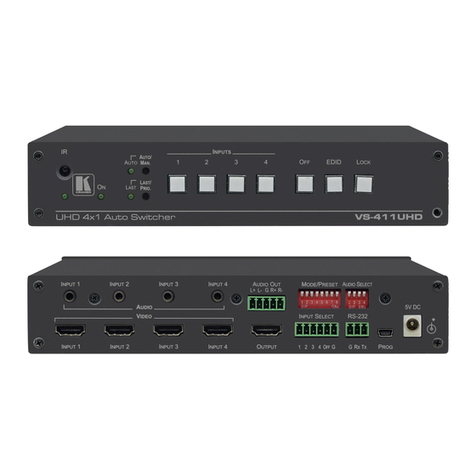
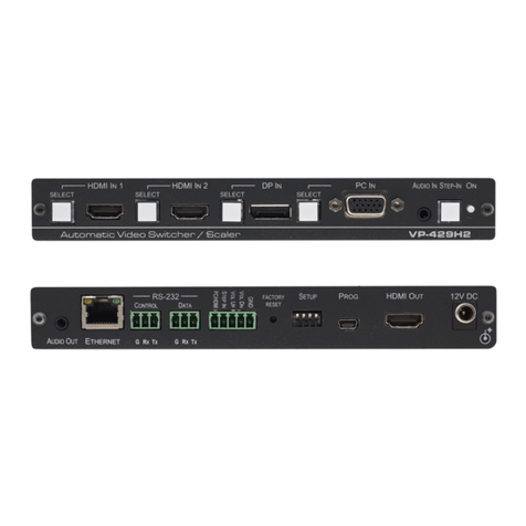
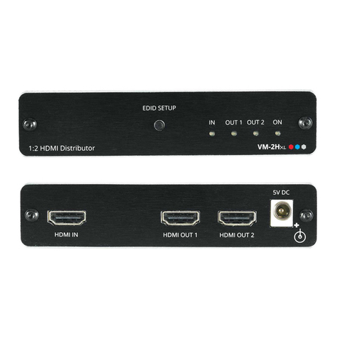
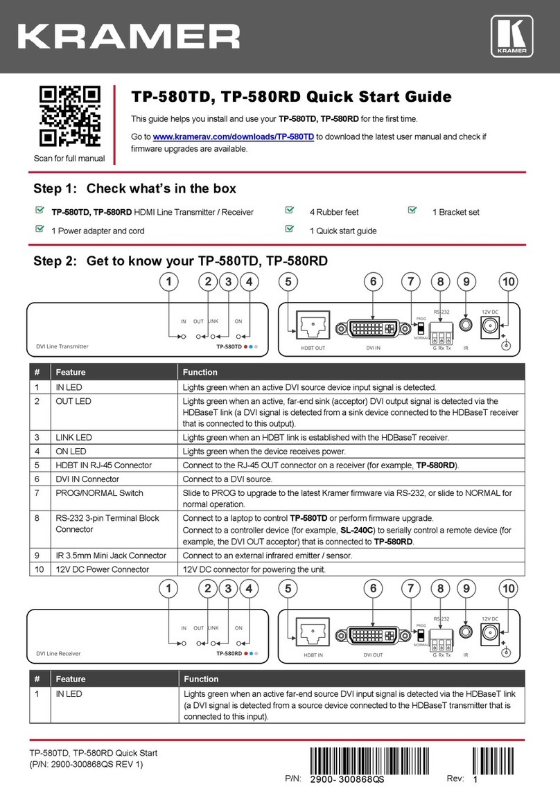
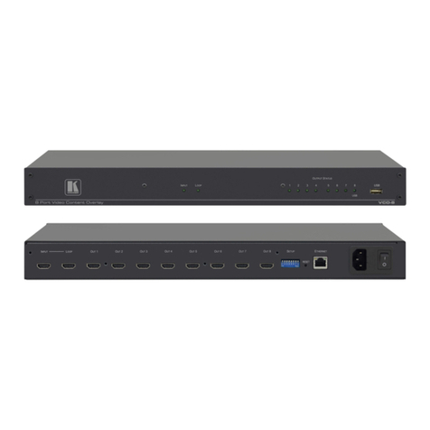
Kramer VP-551X User manual

KramerElectronicsLtd.
VP-551X–Contents
i
Contents
Introduction 1
Getting Started 1
Overview 2
Typical Applications 3
Defining VP-551X 4K Presentation Matrix Switcher Scaler 4
Mounting VP-551X 6
Connecting VP-551X 7
Connecting Output to Balanced/Unbalanced Stereo Audio Acceptor 8
Connecting Balanced/Unbalanced Stereo Audio Source to Balanced Input 8
Microphone Setup 9
Wiring the RJ-45 Connectors 9
Operating and Controlling VP-551X 10
Using Front Panel Buttons 10
Controlling Device Via OSD Menu 11
Operating via Ethernet 19
Using the Embedded Webpages 22
Browsing VP-551X Webpages 22
Selecting Input 24
Setting Device Parameters 27
Changing Output Settings 30
Managing HDCP 33
Managing EDID 34
Setting Audio Parameters 35
Setting RS-232 Port Function 37
Setting Webpage Access 41
Defining Auto Sync Off 44
Defining Auto Switching Mode 45
Defining Lock Mode 45
System Maintenance 46
Viewing Device Information 47
Upgrading the Firmware 48
Technical Specifications 49
Default Communication Parameters 51
Input Resolutions Support 51
Output Resolution Support 52
Default EDID 52
Protocol 3000 55
Understanding Protocol 3000 55
Protocol 3000 Commands 56
Result and Error Codes 64

KramerElectronicsLtd.
VP-551X–Introduction
1
Introduction
Welcometo KramerElectronics! Since1981, KramerElectronics has been providing a world
of unique, creative,and affordablesolutions to the vast range of problems that confrontthe
video, audio, presentation, and broadcasting professional on a daily basis. In recent years,
we have redesigned and upgraded most of our line, makingthe best even better!
Getting Started
We recommendthat you:
•Unpack the equipment carefully and save the original box and packaging materials for
possible future shipment.
•Reviewthe contents of this user manual.
Go to www.kramerav.com/downloads/VP-551X tocheck forup-to-date user manuals,
application programs, and to check if firmwareupgrades are available (where appropriate).
Achieving the Best Performance
•Use only good quality connection cables (we recommendKramerhigh-performance,
high-resolution cables) to avoid interference, deterioration in signal quality due to poor
matching, and elevated noise levels (oftenassociated with low quality cables).
•Do not secure the cables in tight bundles or roll the slack into tight coils.
•Avoid interferencefrom neighboring electrical appliances that may adversely influence
signal quality.
•Position your Kramer VP-551X away from moisture, excessivesunlight and dust.
Safety Instructions
Caution:
•This equipment is to be used only inside a building. It may only be connected to other
equipment that is installed inside a building.
•For products with relay terminals and GPI\O ports, please referto the permitted rating
foran external connection, located next to the terminal or in the User Manual.
•There are no operator serviceable parts inside the unit.
Warning:
•Use only the power cordthat is supplied with the unit.
•Disconnect the power and unplug the unit from the wall before installing.
•Do not open the unit. High voltages can cause electrical shock! Servicingby qualified
personnel only.
•To ensure continuous risk protection, replace fuses only according to the rating
specified on the product label which located on the bottom of the unit.

KramerElectronicsLtd.
VP-551X–Introduction
2
Recycling Kramer Products
The Waste Electrical and Electronic Equipment (WEEE)Directive2002/96/EC aims to reduce
the amount of WEEEsent fordisposal to landfill or incineration by requiring it to be collected
and recycled.To comply withthe WEEEDirective,KramerElectronics has made
arrangements with the European AdvancedRecyclingNetwork (EARN)and will coverany
costs of treatment, recyclingand recovery of waste Kramer Electronicsbranded equipment
on arrival at the EARN facility. For details of Kramer’s recycling arrangements in your
particular country go to our recyclingpages at www.kramerav.com/support/recycling.
Overview
Congratulations on purchasing your Kramer VP-551X 4K Presentation MatrixSwitcher
Scaler.
VP-551X is a versatile, professional presentation scaler/switcher for4K@60 (4:4:4) HDMI™,
and forVGAand composite video signals. The unit scales the video and provides options to
use the embedded HDMIaudio or to select the companionaudio channel from one of ten
analog audio input signals. Afterprocessing and scaling, the embedded AV signal is sent to
the HDMIand the HDBaseT outputs simultaneously, and the audio is also sent to a balanced
stereo audio output, S/PDIFdigital output and a pair of loudspeakers.
VP-551X provides exceptional quality, advanced and user-friendly operation, and flexible
control.
Exceptional Quality
•High-Resolution Video –Supports and scales to/from resolutions up to 4K@60Hz
(4:4:4) on the HDMIinputs and output, and 4K@60Hz (4:2:0) on the HDBaseToutput.
•Complies with HDMI,HDCP 2.2 and HDR10standards.
•HDMISupport –HDR10, CEC,xvYCC color(on input), Dolby TrueHD/DTS-HD Master
Audio (by-pass), as specified in HDMI2.0 as specified in HDMI2.0.
•Professional Video Quality –Provides selectable aspect ratios (full, best fit,over scan,
under scan, letter box and pan scan). Includes built-in ProcAmpforcolor, hue,
sharpness, noise, contrast and brightness control. Supports PixPerfect™ Scaling
Technology, Kramer’s precision pixel mapping and high-quality scaling technology.
High-quality 3:2 and 2:2 pull-down de-interlacing and full up-scaling and down-scaling of
all video input signals.
•High-PerformanceSwitcher/Scaler –Scales HDMI,VGAand Composite video signals
foroutput to two mirrored outputs: HDMIand HDBaseT. Constant output sync prevents
signal disruption when switching between inputs and when no video is detected.
•PowerfulAudio Features –Including DSP with audio equalization, mixing,delay and
more.
•HDTVCompatible.

KramerElectronicsLtd.
VP-551X–Introduction
3
Advanced and User-friendly Operation
•4K and Legacy Inputs –8 4K@60 (4:4:4) HDMIinputs, 1 VGAinput, and 1 CV
(composite video) input.
•Versatile Powering Options –Powered by universal power supply (100-240V AC)and
provides PoEpower to a compatible HDBaseT device.
•Non-Volatile Memory –Savesfinal settings before shutdown and retains them fornext
power up.
•Convenient Control Options –Local control via frontpanel buttons, RS-232, IR remote,
and OSD.Long-distance control via embedded webpages and Ethernet.
•Easy Installation –19” enclosure for rack mounting a unit in a 1U rack space with
included rack ears and universal 100-240V AC power connection.
•Auto-switching and auto-scanning of inputs.
•AdvancedEDID management per input.
Flexible Connectivity
•Versatile Audio Options –Includes a companionanalog audio input foreach of the 10
video inputs, enabling the user to embed a separate analog audio channel into each
video signal or to bypass an embedded audio input (forexample, to support
multi-channel, compressed audio formatslike Dolby and DTS).
•Provides 2 independent microphone inputs on 6.3mm connectors(each with optional
48V phantom power) formixing, switching or talk–over.
•On the output, besides the audio embedded on HDMIand HDBaseT outputs, the audio
signal is also extracted (de-embedded) and output as balanced stereo analog audio,
and as digital audio through an S/PDIFconnected device, as well as amplified to 20W
per channel forconnection to loudspeakers.
•Video Inputs –8 HDMI,1 PC and 1 CV.
•Video Outputs –1 HDBaseTand 1 HDMI.
Typical Applications
VP-551X is ideal forthe following typical applications:
•Projection systems in conferencerooms,boardrooms, hotels and churches.
•Hometheater up-scaling.
Controlling your VP-551X
Control your VP-551X directly via the frontpanel push buttons (with on-screen menus, or:
•By RS-232 serial commandstransmitted by a touch screen system,PC, or other serial
controller.
•Remotely,from the infrared remote control transmitter.
•Via the Ethernet using built-in user-friendly webpages.

KramerElectronicsLtd.
VP-551X–DefiningVP-551X4KPresentation Matrix SwitcherScaler
4
Defining VP-551X 4K
Presentation Matrix Switcher
Scaler
This section defines VP-551X.
Figure1: VP-551X4K PresentationMatrix SwitcherScaler Front Panel
#
Feature
Function
IR Receiver
Receives signals from the remote-control transmitter.
IR LED
Lights when the unit accepts IR remote commands.
HDMI™
Press to select the HDMI input (from INPUT 1 to INPUT 8).
PC
Press to select the computer graphics input.
CV
Press to select the composite video input.
FREEZE Button
Press to freeze/unfreeze the output video image.
Not applicable when in video bypass mode.
MUTE Button
Press to toggle between muting (blocking out thesound) and enabling the
audio output (both line and speakers).
Muting the audio is not applicable when in audio bypass mode.
MENU Button
Press to enter/escape the on-screen display (OSD)menu.
Navigation
Buttons
Press to decrease numerical values or select from several definitions.
When not within the OSD menu mode, press to decrease the output volume.
Press to move up the menu list.
Press to increase numerical values orselect from several definitions.
When not within the OSD menu mode, press to increase the output volume.
Press to move down the menu list.
ENTER
Press to accept changes and change the SETUP parameters.
RESET TO
XGA/1080p Button
Press and hold for about 5 seconds to toggle resetting the video resolution to
XGA or 1080p.
PANEL LOCK Button
Press and hold forabout 3 seconds to lock/unlock thefront panel buttons
(see Locking and Unlocking Front Panel Buttons on page 10).
1
2
3
4
5
6
7
8
9
10
11

KramerElectronicsLtd.
VP-551X–DefiningVP-551X4KPresentation Matrix SwitcherScaler
5
Figure2: VP-551X4K PresentationMatrix SwitcherScaler Rear Panel
#
Feature
Function
VIDEO INPUT
Connectors
HDMI™
Connect to an HDMI source (from INPUT 1 to INPUT 8).
PC 15-pin HD
Connect to a computer graphics source.
CV RCA
Connect to a composite video source.
48V MIC 1 Switch
Move up (ON) to select phantom power for a condenser type
microphone; down (OFF) to select a dynamic type microphone.
MIC 1 6mm Jack
Connect to the microphone source 1.
48V MIC 2 Switch
Move up (ON) to select phantom power for a condenser type
microphone; down (OFF) to select a dynamic type microphone.
MIC 2 6mm Jack
Connect to the microphone source 2.
AUDIO INPUT
Unbalanced
Stereo
Terminal
Blocks
HDMI
Connect to an analog audio HDMI source (from 1 to 8).
PC IN
Connect to an analog audio computergraphics source.
CV IN
Connect to an analog audio composite video source.
LINE OUT Balanced Stereo 5-pin
Terminal Block Connector
Connect to a balanced stereo analog audio acceptor.
S/PDIF OUT RCA Connector
Connect to a digital audio acceptor.
SPEAKER 4-pin Terminal Block
Connector
Connect to a pair of loudspeakers.
Mains Socket
Connect the mains power cord.
Mains Fuse Holder
Fuse forprotecting thedevice.
Power Switch
Switch forturning the unit ON or OFF.
HDMI™ OUT
Connect to the HDMI acceptor.
HDBT OUT RJ-45 Connector
Connect to an HDBaseT receiver.
RS-232 9-pin
D-sub
Connector
DATA
Connect to a PC or controller to tunnel RS-232 via HDBT OUT or
connect to the output display to control it.
CTRL
Connect to a PC or remote controller to control VP-551X or
connect to a device which you want to control via the VP-551X
(see Controlling an External Device onpage 38).
ETHERNET RJ-45 Connector
Connects to the PC or other Serial Controller through computer
networking.
12
13
14
15
16
17
18
19
20
21
22
23
24
25
26
27
28
29
30
31
32

KramerElectronicsLtd.
VP-551X–MountingVP-551X
6
Mounting VP-551X
This section provides instructions formounting VP-551X. Beforeinstalling, verify that the
environment is within the recommendedrange:
•Operation temperature –0to 40C (32 to 104F).
•Storage temperature –-40to +70C (-40 to +158F).
•Humidity –10% to 90%, RHLnon-condensing.
Caution:
•Mount VP-551X beforeconnecting any cables or power.
Warning:
•Ensure that the environment(e.g., maximum ambienttemperature & air flow)is
compatible forthe device.
•Avoid uneven mechanicalloading.
•Appropriate consideration of equipment nameplate ratings should be used foravoiding
overloading of the circuits.
•Reliable earthing of rack-mountedequipment should be maintained.
Tomount the VP-551X on a rack
Attach both rack ears by removing the screws from eachside of the
machine and replacing those screwsthrough the rack ears or place
the machine on a table.
For more informationgo to www.kramerav.com/downloads/VP-551X

KramerElectronicsLtd.
VP-551X–ConnectingVP-551X
7
Connecting VP-551X
Always switchoff the power to each devicebefore connecting it to your VP-551X. After
connecting your VP-551X, connectits power and then switch on the power to each device.
Figure3: Connectingtothe VP-551X Rear Panel
Toconnect the VP-551X as illustrated in the example in Figure 3:
1. Connect a computergraphics source (forexample, a laptop) to the 15-pin HD Input
connector .
2. Connect a composite video source (forexample, a DVDplayer) to the CVRCA
connector .
3. Connect up to 8 HDMIsources (forexample,a Blu-ray player to HDMI5) to the HDMI
connectors .
4. Connect up to 10 balanced audio sources (forexample, the PC audio source to the CV
IN AUDIO INPUT) to the AUDIO IN terminal block connectors .
5. Connect a microphone to the MIC2 6mm jack and set the 48V switchon or off,as
required .
6. Connect the HDMIOUTconnector to an acceptor(for example,a display).
7. Connect the HDBTOUTconnector to an acceptor (forexample, Kramer TP-580R
receiverthat is connected to a projector).
8. Connect the S/PDIF OUT RCAconnector to a digital audio acceptor (forexample,
an audio power amplifier).
9. Connect the SPEAKER 4-pin terminal block connector to speakers (for example,
KramerYarden 6-O speakers).
10.Connect the RS-232 DATA9-pin D-sub connector to the RS-232port on the display
to control it.
11.Connect the RS-232 CTRL9-pin D-sub connector to the RS-232 port on a controller
(forexample, a laptop) to control the VP-551X.
12.Connect the ETHERNETRJ-45port to the Ethernet.
13
14
12
21
18
14
28
28
28
24
30
31
32

KramerElectronicsLtd.
VP-551X–ConnectingVP-551X
8
13.Connect the power cord to the VP-551X mains socket and to the mains electricity
(not shown in Figure 3).
The LINE OUT 5-pin terminal block connector , audio acceptor, and power cord are not
shown in Figure 3.
Connecting Output to Balanced/Unbalanced Stereo
Audio Acceptor
The following are the pinouts forconnecting the output to a balanced or unbalanced stereo
audio acceptor:
Figure 4: Connecting to aBalanced Stereo Audio
Acceptor
Figure 5: Connecting to an Unbalanced Stereo Audio
Acceptor
Connecting Balanced/Unbalanced Stereo Audio
Source to Balanced Input
The following are the pinouts for connecting a balanced or unbalanced stereo audio source to
the balanced input:
Figure 6: Connecting a Balanced Stereo Audio
Source to the Balanced Input
Figure 7: Connecting an Unbalanced Stereo Audio
Source to the Balanced Input
22
13

KramerElectronicsLtd.
VP-551X–ConnectingVP-551X
9
Microphone Setup
The following are the microphone pinouts.
Condenser Microphone Pinout
Dynamic Microphone Pinout
Figure8: CondenserMicPinout
Figure9: DynamicMicPinout
Wiring the RJ-45 Connectors
This section defines the HDBaseT pinout, using a straight pin-to-pin cable with RJ-45
connectors.
For HDBTcables, it is recommendedthat the cable ground shielding be connected/soldered
to the connector shield.
EIA /TIA 568B
PIN
Wire Color
1
Orange / White
2
Orange
3
Green / White
4
Blue
5
Blue / White
6
Green
7
Brown / White
8
Brown

KramerElectronicsLtd.
VP-551X–Operatingand ControllingVP-551X
10
Operating and Controlling VP-
551X
Using Front Panel Buttons
Press the VP-551X frontpanel buttons to:
•Select the required INPUT(HDMI,PC or CV).
•Freeze and/or mute the output.
•Reset the resolution to XGA/1080p.
•Lock / Unlock the frontpanel buttons (see Locking and Unlocking Front Panel Buttons
on page 10).
•Control the devicevia the OSD menu,using the MENU,ENTER,and navigation buttons
(see Controlling DeviceVia OSD Menu on page 11).
Locking and Unlocking Front Panel Buttons
The front panel buttons can be locked (disabled) to prevent unintentional pressing of the
buttons. Locking modes are set via the Advanced webpage (see Defining Lock Mode
on page 45) or the ADVANCED OSD menu (see Setting Lock Mode Functionality
on page 18).
Locking Procedure
The locking procedure is the same for all locking modes.
To lock the front panel buttons:
•Press and hold PANEL LOCK forabout 3 seconds.
The Panel Lock button lights blue and the front panel buttons are locked.
Unlocking Procedure
Unlocking procedure is specific for lockingmodes.
Tounlock the front panel buttons:
•For All or MenuOnly Lock modes –Press and hold PANEL LOCK forabout 3
seconds.
•For All & Save or Menu Only & Save Lock modes –Press and hold PANEL LOCK
and RESETTO XGA/1080P simultaneously forabout 3 seconds.
The Panel Lock button light goes out and the front panel buttons are unlocked.
11
11
11
10

KramerElectronicsLtd.
VP-551X–Operatingand ControllingVP-551X
11
Controlling Device Via OSD Menu
Use the OSD buttons to control the VP-551X via the OSD menu(for moreinformation,
see Navigating OSD Buttons on page 11).
The default OSD timeout is set to 10 seconds.
Use the OSD menuto perform the following operations:
•Setting Image Parameters on page 12.
•Selecting the Input Signal on page 12.
•Setting Output Parameters on page 13.
•Setting the Audio Source on page 14.
•Setting OSD Parameters on page 15.
•Managing EDID on page 16.
•Setting HDCP on page 16.
•Setting Sleep Mode on page 17.
•Setting Switching Mode on page 17.
•Setting Ethernet Parameters on page 17.
•Setting Lock Mode Functionality on page 18.
•Setting Daily Reset Schedule on page 18.
•Viewing DeviceHours. on page 18.
•Viewing DeviceInformation on page 19.
•PerformingFactory Reset on page 19.
Navigating OSD Buttons
Toenter and use the OSD menu buttons:
1. Press MENU.
2. Press:
▪ENTER toacceptchanges and to change the menusettings.
▪Arrow buttonsto movethrough the OSD menu, whichis displayed on the video
output.
▪EXIT to exit the menu.

KramerElectronicsLtd.
VP-551X–Operatingand ControllingVP-551X
12
Setting Image Parameters
Toset the image parameters:
1. On the front panel press MENU.Themenu appears.
2. Click Picture and define the image parameters according to the informationin the
following table:
Menu Item
Function
Contrast
Set the contrast.
Brightness
Set the brightness.
Finetune
Input Signal
Function
PC
Phase –set the phase of the sampling clock.
Clock –set the frequency of the sampling clock.
H-Position –set the horizontal picture position.
V-Position –set the vertical picture position.
Video
HUE –set the color hue.
Saturation –set the color saturation.
Sharpness –set the sharpness of the picture.
NR (Noise Reduction) –select the noise reduction filter:
Off (default), Low, Middle or High.
Color
Set the Red, Green and Blue shades.
Selecting the Input Signal
Toset the input source:
1. On the front panel press MENU.Themenu appears.
2. Click Input and select the input source:
▪HDMI1(default) to HDMI8.
▪PC.
▪CV.

KramerElectronicsLtd.
VP-551X–Operatingand ControllingVP-551X
13
Setting Output Parameters
Toset the output parameters:
1. On the front panel press MENU.Themenu appears.
2. Click Output and define the output parameters according to the informationin the
following table:
Menu Item
Function
Size
Set the size of the image: Full, Overscan, Under 1, Under 2, Letterbox, Panscan, Best fit
(default), Follow In.
Bypass mode
(4Kin->4Kout)
Yes (Bypass): Select for 4K HDMI signals to bypass thescaler (no video processing).
No (Scaler): Select to always scale the HDMI signals.
Resolution
Select the output resolution(default, NATIVE HDMI):
Appears as
Output Resolution
Appears as
Output Resolution
640x48060
640x480@60Hz
800x60060
800x600@60Hz
1024x76860
1024x768@60Hz
1280x76860
1280x768@60Hz
1280x80060
1280x800@60Hz
1280x102460
1280x1024@60Hz
1360x76860
1360x768@60Hz
1400x105060
1400x1050@60Hz
1440x90060
1440x900@60Hz
1600x120060
1600x1200@60Hz
1680x105060
1680x1050@60Hz
1920x120060RB
1920x1200@60HzRB
2560x160060RB
2560x1600@60HzRB
1920x108060
1920x1080@60Hz
1280x72060
1280x720@60Hz
2560x144060RB
2560x1440@60HzRB
720x480P60
720x480P@60Hz
720x576P50
720x576P@50Hz
1280x720P50
1280x720P@50Hz
1280x720P60
1280x720P@60Hz
1920x1080P24
1920x1080P@24Hz
1920x1080P25
1920x1080P@25Hz
1920x1080P30
1920x1080P@30Hz
1920x1080P50
1920x1080P@50Hz
1920x1080P60
1920x1080P@60Hz
2560x1080P50
2560x1080P@50Hz
2560x1080P60
2560x1080P@60Hz
3840x2160P24
3840x2160P@24Hz
3840x2160P25
3840x2160P@25Hz
3840x2160P30
3840x2160P@30Hz
3840x2160P50(420)
4k2k @50Hz(4:2:0)
3840x2160P60(420)
4k2k @60Hz(4:2:0)
For HDMI only
3840x2160P50
3840x2160P@50Hz
3840x2160P60
3840x2160P@60Hz

KramerElectronicsLtd.
VP-551X–Operatingand ControllingVP-551X
14
Setting the Audio Source
Toset the audio source:
1. On the front panel press MENU.Themenu appears.
2. Click Audio and define the audio parameters according to the information in the
following table:
Menu Item
Function
Input Volume
Set the analog audio input volume forHDMI 1 to HDMI 8, PC and CV.
Output Volume
Set the LINE OUT output volume
Speaker Volume
Set the SPEAKER volume.
Setting
Delay
Set the audio delay time to 40ms (default),50ms, 60ms to 200ms
(in 10ms steps).
DRC
Set dynamic range compression Off (default) or On.
Bass
Set the output bass level.
Treble
Set the output treble level.
Loudness
Set loudness Off (default) or On.
Mute
Set audio mute to Off (default)orOn.
Speaker Mute
Set audio speaker mute to Off (default) orOn.
Source
Set each HDMI input (1 to 8) audio source to Automatic (default), Analog or
Embedded.
Mic Settings
Mic Mode
Set to Off (default), Mixer, Talkover or Mic Only.
Mic Select
Set to Mic 1 (default), Mic 2 or Both.
When Mic Mode is set to Talkover (see Talkover Mode on page 15), set the
following:
Depth [%]
Set the depth value to determine the decrease of theaudio
level during microphone takeover (press + to further
decrease the talkoveraudio output level; press –to lessen
the talkover output audio decrease level).
Trigger [dB]
Set the triggervalue to determine the microphone threshold
level that triggers the audio output level decrease.
Attack Time
Set the attack time to set the transitiontime of the audio level
reduction after the signal rises above the threshold level.
Hold Time
Set the hold time to definethe time period talkoverremains
active although the signal falls belowthe threshold level (for
a short period of time).
Release Time
Set the release time to definethe transition time forthe
audio level to return from its reduced level to its normal level
afterthe Hold Time period.
Mic Volume
Set microphone volume (MIC 1, MIC 2).
Embedded In -> Out
Apply DSP (default)to the embedded audio or ByPass it.

KramerElectronicsLtd.
VP-551X–Operatingand ControllingVP-551X
15
Talkover Mode
Figure10: Talkover Mode
Setting OSD Parameters
Toset the OSD parameters:
1. On the front panel press MENU.Themenu appears.
2. Click OSD and define the OSD parameters according to the information in the following
table:
Menu Item
Function
H-Position
Set the horizontal position of the OSD.
V-Position
Set the vertical position of the OSD.
Timer
Set the timeout period to Off orup to 60 seconds (default 10).
Transparency
Set the OSD background between 100 (transparent) and 0 (opaque).
Display
Select the information displayed on-screen during operation:
Info (default) –the information appears for 10 seconds.
On –the information appears constantly.
Off –the information does not appear.

KramerElectronicsLtd.
VP-551X–Operatingand ControllingVP-551X
16
Managing EDID
Tomanage the EDID:
1. On the front panel press MENU.Themenu appears.
2. Click EDID Manage and define the EDIDparameters according to the informationin the
following table:
Menu Item
Function
EDID on HDMI (1 to 8)
For each HDMI input, select a built-in EDID and press enter:
Def.1080P (default), Def. 4K(3G), Def. 4K(4:2:0), Def. 4K(6G),
HDMI Output or HDBT Output.
EDID on PC
Default
Setting HDCP
Toset the HDCP on the inputs and output:
1. On the front panel press MENU.Themenu appears.
2. Click Advanced and define the HDCP parameters according to the informationin the
following table:
Menu Item
Function
HDCP On Input
Set HDCP support on HDMI 1 to HDMI 8 inputs to ON (default) or
OFF.
Note that:
1. HDCP must be enabled (ON) in orderto support HDCP
encrypted sources.
2. Sources such as Mac computers always encrypt their outputs
when detecting that the sink supports HDCP. If the content
does not require HDCP, you can prevent these sources from
encrypting by disabling (OFF) HDCP on the input.
HDCP On Output
Select Follow Output (default) or Follow Input on each output (HDMI
OUT and HDBT OUT).
Select FollowOutput (recommended) for thescaler to match its HDCP
output to the HDCP setting of the HDMI/HDCP acceptor to which it is
connected.
Select FollowInput to change its HDCP output setting according to
the HDCP of the input (recommended when the HDMI/HDCP output is
connected to a splitter/switcher).

KramerElectronicsLtd.
VP-551X–Operatingand ControllingVP-551X
17
Setting Sleep Mode
VP-551X enables configuring if and when a connecteddisplay enters sleep mode using the
Auto Sync Off feature.Auto Sync Off turnsoff the output after a period of not detecting a valid
video signal on the input(s) until a valid input is again detected or any keypadis pressed.
Toset the Auto Sync Off:
1. On the front panel press MENU.Themenu appears.
2. Click ADVANCED andselect Auto Sync Off.
3. DefineAuto Sync Off accordingtothe informationin the following table:
Menu Item
Function
Disable (default)
To leave outputs active at all times.
Slow
To disable outputs after ~ 2 minutes of no input detection.
Fast
To disable outputs after ~ 10 seconds of no input detection.
Immediate
To disable outputs ~ 0.5 seconds afterdetecting a loss of input signal.
Setting Switching Mode
Toset the switching mode:
1. On the front panel press MENU.Themenu appears.
2. Click Advanced and select Auto Switching.
3. Select the switching mode accordingto the information in the following table:
Menu Item
Function
Off (default)
For manual switching.
Auto Scan
Scans for avalid input when no signal is found on the selected input.
Last Connected
Automatically switches to the last connected input and reverts back
to the last selected input afterthat input is lost.
Setting Ethernet Parameters
Toset the Ethernet :
1. On the front panel press MENU.Themenu appears.
2. Click Advanced and define the Ethernet parameters according to the information in the
following table:
Menu Item
Function
IP Mode
Select Static IP (default) or DHCP.
Static IP Address
Enter to change the IP address.
Subnet Mask
Enter to change the subnet mask.
Default Gateway
Enter to change the default gateway.
TCP Port
Enter TCP port # (5000, by-default).
UDP Port
Enter UDP port # (50000, by-default).
IP
View the current IP address.
MAC ADDRESS
View the MAC address.
Link Status
View the link status.

KramerElectronicsLtd.
VP-551X–Operatingand ControllingVP-551X
18
Setting Lock Mode Functionality
Toset the functionality of the LOCK frontpanel button:
1. On the front panel press MENU.Themenu appears.
2. Click Advanced and select Lock Mode.
3. Set a panel lock mode according to the informationin the following table:
Menu Item
Function
All
All front panel buttons are locked.
All & Save
All front panel buttons are locked and remain locked after cycling power.
Menu Only
Menu buttons are locked.
Menu & Save
Menu buttons are locked and remain locked after cycling power.
To unlock the front panels, see Lockingand UnlockingFront Panel Buttons on page 10.
Setting Daily Reset Schedule
For units operating 24/7, the Daily Reset Timermay be used to automatically reset the unit
each day.
Note that this functionreboots the unit –it does not reset any of the parameters.
Toset a daily reset schedule:
1. On the front panel press MENU.Themenu appears.
2. Click Advanced and select Daily Reset.
3. Set the daily reset schedule.
Menu Item
Function
Daily Reset
Disable daily reset (Off, default) or enable daily reset (On).
Next Reset (h)
Set the number of hours before
the next reset.
Set for the “Next Reset” to fix the time
that the unit will be reset each day.
Next Reset (m)
Set the number of minutes
before the next reset.
AfterPower-Up
Define behavior following a power cycle:
Disable –The Daily Reset Timer is turned off.
Restart –The timer restarts when the unit is powered up (i.e., from then
onwards, the unit resets each day at the time that the unit is powered up).
Resume –The timer continues running afterpower returns (while
powered down, the timer does not run).
Viewing Device Hours.
Lifetimeshows the total number of hours that the machine has been in operation.
Toview device hours:
1. On the front panel press MENU.Themenu appears.
2. Click Advanced.
3. View Lifetimeand view device hours.
Other manuals for VP-551X
2
Table of contents
Other Kramer Media Converter manuals

Kramer
Kramer VP-740 ProScale User manual

Kramer
Kramer FC-331A User manual

Kramer
Kramer VP-426C User manual

Kramer
Kramer KDS-EN6 User manual

Kramer
Kramer VP-505 User manual

Kramer
Kramer VP-424 User manual

Kramer
Kramer VM-212HDMI User manual

Kramer
Kramer FC-331 User manual

Kramer
Kramer VP-505 User manual

Kramer
Kramer TOOLS VP-100 User manual

Kramer
Kramer VM-100CB User manual

Kramer
Kramer VP-481 User manual

Kramer
Kramer VP-701XL User manual

Kramer
Kramer 6808HDxl User manual

Kramer
Kramer VP-791 User manual

Kramer
Kramer VW-16 User manual

Kramer
Kramer VP-426C User manual

Kramer
Kramer FC-332 User manual

Kramer
Kramer DigiTOOLS VM-2HDMI User manual

Kramer
Kramer VP-441 User manual