Kramer VP-505 User manual

Kramer Electronics, Ltd.
USER MANUAL
Model:
VP-505
3G HD-SDI to Video Scan Converter

Contents
i
Contents
1Introduction 1
2Getting Started 1
2.1 Quick Start 2
3Overview 3
4Defining the VP-505 3G HD-SDI to Video Scan Converter 4
5Connecting the VP-505 3G HD-SDI to Video Scan Converter 5
6Operating the VP-505 3G HD-SDI to Video Scan Converter 6
6.1 Using the Front Panel Buttons 6
6.2 Using the OSD 6
6.2.1 The Main Menu 7
6.2.2 The Display Submenu 7
6.2.3 The Color Submenu 8
7Technical Specifications 9
Figures
Figure 1: VP-505 3G HD-SDI to Video Scan Converter Front Panel 4
Figure 2: VP-505 3G HD-SDI to Video Scan Converter Rear Panel 4
Figure 3: Connecting the VP-505 3G HD-SDI to Video Scan Converter 5
Tables
Table 1: VP-505 3G HD-SDI to Video Scan Converter Front Panel Features 4
Table 2: VP-505 3G HD-SDI to Video Scan Converter Rear Panel Features 4
Table 3: The Main Menu Parameters and Functions 7
Table 4: The Display Submenu Parameters 7
Table 5: The Color Submenu Parameters 8
Table 6: Technical Specifications of the VP-505 3G HD-SDI to Video Scan Converter 9

Introduction
1
1 Introduction
Welcome to Kramer Electronics! Since 1981, Kramer Electronics has been
providing a world of unique, creative and affordable solutions to the vast range of
problems that confront the video, audio, presentation and broadcasting professional
on a daily basis. In recent years, we have redesigned and upgraded most of our
line, making the best even better! Our 1,000-plus different models now appear in
11 groups1
Thank you for purchasing your Kramer MegaTOOLS®VP-505 3G HD-SDI to
Video Scan Converter which is ideal for:
that are clearly defined by function.
•Projection systems in conference rooms, boardrooms, hotels and churches
•Monitoring of SDI signals using cheap video displays
•Displaying down-scaled SDI in legacy systems
•Making video recordings of SDI content
The package includes the following items:
•VP-505 3G HD-SDI to Video Scan Converter
•Power adapter
•This user manual2
2 Getting Started
We recommend that you:
•Unpack the equipment carefully and save the original box and packaging
materials for possible future shipment
•Review the contents of this user manual
•Use Kramer high-performance, high-resolution cables3
1 GROUP 1: Distribution Amplifiers; GROUP 2: Switchers and Matrix Switchers; GROUP 3: Control Systems;
GROUP 4: Format/Standards Converters; GROUP 5: Range Extenders and Repeaters; GROUP 6: Specialty AV Products; GROUP 7:
Scan Converters and Scalers; GROUP 8: Cables and Connectors; GROUP 9: Room Connectivity;
GROUP 10: Accessories and Rack Adapters; GROUP 11: Sierra Products
2 Download up-to-date Kramer user manuals from http://www.kramerelectronics.com
3 The complete list of Kramer cables is available at http://www.kramerelectronics.com

KRAMER: SIMPLE CREATIVE TECHNOLOGY
Getting Started
2
2.1 Quick Start
This quick start chart summarizes the basic setup and operation steps.

Overview
3
3 Overview
The Kramer VP-505 3G HD-SDI to Video Scan Converter is a high-quality scan
converter for down-scaling SDI, HD-SDI and 3G HD-SDI signals to PAL or
NTSC video.
The VP-505 also features:
•A maximum data rate of 3Gbps
•An SDI input
•An equalized and re-clocked loop output (up to 3G HD-SDI)
•Multi-standard operation: SDI (SMPTE 259M and SMPTE 344M), HD-SDI
(SMPTE 292M) and 3G HD-SDI (SMPTE 424M)
•Simultaneous high-quality composite video and s-Video (Y/C) outputs
•A unbalanced stereo audio output
•An OSD (On-screen Display) accessible via the front panel buttons for easy
setup and adjustment
•A built-in ProcAmp for convenient signal adjustment
•A non-volatile memory that retains the last settings used
•A freeze button
•An external 5V DC source, making it suitable for field operation
•Operation directly via the front panel push buttons and the OSD
To achieve the best performance:
•Use only good quality connection cables1
•Avoid interference from neighboring electrical appliances that may adversely
influence signal quality
to avoid interference, deterioration
in signal quality due to poor matching, and elevated noise levels (often
associated with low quality cables)
•Position your Kramer VP-505 away from moisture, excessive sunlight and
dust
Caution: No operator serviceable parts inside the unit
Warning: Use only the Kramer Electronics input power wall
adapter that is provided with the unit
Warning: Disconnect the power and unplug the unit from the wall
before installing
1 Available from Kramer Electronics at http://www.kramerelectronics.com
!

KRAMER: SIMPLE CREATIVE TECHNOLOGY
Defining the VP-505 3G HD-SDI to Video Scan Converter
4
4 Defining the VP-505 3G HD-SDI to Video Scan Converter
Figure 1 and Table 1 define the front panel of the VP-505.
Figure 1: VP-505 3G HD-SDI to Video Scan Converter Front Panel
Table 1: VP-505 3G HD-SDI to Video Scan Converter Front Panel Features
# Feature Function
1 ON LED Lights green when the unit is powered on
2 SDI LED Lights blue when an SDI signal is detected on the input
3 MENU Button Press to display the OSD (On-screen Display) menu.
When the OSD is not displayed, press together with the – button to set the output
resolution to NTSC
4 ENTER Button In the OSD, press to select the highlighted menu item.
When the OSD is not displayed, press together with the + button to set the output
resolution to PAL
5 – Button In the OSD, press to step up through the options or to decrement the parameter value
6 + / FREEZE Button In the OSD, press to step down through the options or to increment the parameter
value.
When the OSD is not displayed, press to freeze the display
Figure 2 and Table 2 define the rear panel of the VP-505.
Figure 2: VP-505 3G HD-SDI to Video Scan Converter Rear Panel
Table 2: VP-505 3G HD-SDI to Video Scan Converter Rear Panel Features
# Feature Function
1 SDI IN BNC Connector Connect to the SDI source
2 SDI OUT BNC Connector Connect to the SDI acceptor (loop). The signal is
re-clocked and equalized

Connecting the VP-505 3G HD-SDI to Video Scan Converter
5
# Feature Function
3
AUDIO OUT RCA
Connectors
LEFT Channel
Unbalanced Stereo
Audio
Connect to the left channel of the unbalanced stereo audio
acceptor
4 RIGHT Channel
Unbalanced Stereo
Audio
Connect to the right channel of the unbalanced stereo
audio acceptor
5 CV OUT BNC Connector Connect to the composite video acceptor
6 Y/C OUT 4-pin Connector Connect to the Y/C (s-Video) acceptor
7 5V DC Connect to the power adapter, center pin positive
5 Connecting the VP-505 3G HD-SDI to Video Scan Converter
Always switch off the power to each device before connecting them to
your VP-505. After connecting your VP-505, connect its power and then
switch on the power to each device.
Figure 3: Connecting the VP-505 3G HD-SDI to Video Scan Converter
To connect the VP-505, as illustrated in the example in Figure 3:
1. Connect the SDI video source (for example, a digital camera) to the SDI IN
BNC connector.
2. Connect the SDI OUT BNC connector to the SDI acceptor (for example, an
SDI display).
i

KRAMER: SIMPLE CREATIVE TECHNOLOGY
Operating the VP-505 3G HD-SDI to Video Scan Converter
6
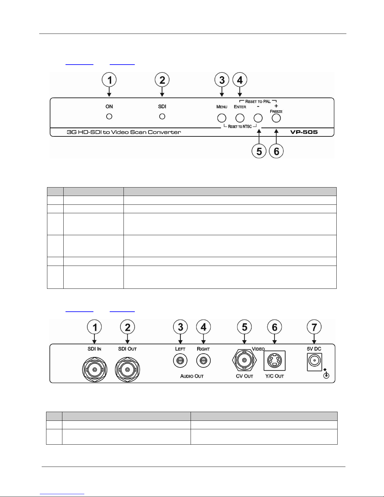
3. Connect the LEFT and RIGHT AUDIO OUT RCA connectors to the audio
acceptor (for example, a stereo audio amplifier).
4. Connect the VIDEO CV OUT BNC connector to the composite video
acceptor (for example, a composite video display).
5. Connect the VIDEO Y/C OUT 4-pin connector to a Y/C (s-Video) acceptor
(for example, an s-Video recorder).
6. Connect the power adapter to the 5V DC power socket and to the mains
electricity (not shown in the illustration).
6 Operating the VP-505 3G HD-SDI to Video Scan Converter
The VP-505 is operated directly via the front panel buttons and via the OSD menu
(see Section 6.2
6.1 Using the Front Panel Buttons
).
During normal operation (without the OSD), the front panel buttons perform in the
following manner:
•MENU: Displays the OSD Main Menu (see Section 6.2
•FREEZE: Freezes the display. Press a second time to unfreeze the display
). Press a second
time to close the OSD
•MENU and –: Press together to set the output to NTSC
•ENTER and FREEZE: Press together to set the output to PAL
6.2 Using the OSD
The OSD is used to set a variety of parameters.
When using the OSD, the front panel buttons operate in the following manner:
•MENU: Opens the OSD main menu (see Table 3). Press a second time to
close the OSD
•ENTER: Selects the highlighted menu item or parameter
•– : Steps up through the menu list or decrements the parameter value
•+ : Steps down through the menu list or increments the parameter value
Note: After a period of 15 sec with no button activity, the OSD menu times-out
automatically.
Example of Using the OSD Menu
To set the green offset value of the display output (for example, to 42):
1. From normal operation, press MENU.
The OSD main menu appears on the screen.
2. Press the + or –button to highlight COLOR.
COLOR changes to green.
3. Press ENTER.

Operating the VP-505 3G HD-SDI to Video Scan Converter
7
The Display submenu is displayed.
4. Press the + or –button to highlight G OFFSET.
G OFFSET changes to green.
5. Press ENTER.
The G OFFSET parameter changes to red.
6. Press the + button to increase the value to 42.
7. Press ENTER to set the value.
G OFFSET is highlighted in green.
8. To exit to normal operation, press MENU or wait for the OSD to timeout.
6.2.1 The Main Menu
Table 3 defines the Main menu parameters and functions.
Table 3: The Main Menu Parameters and Functions
Parameter Function
DISPLAY Sets the output resolution, size and aspect ratio (see Table 4)
CONTRAST Sets the output contrast Value range: 0-255 Default: 105
BRIGHTNESS Sets the output
brightness
Value Range: 0-192 Default: 96
COLOR Sets the output color parameters (see Table 5)
SDI AUDIO Selects which embedded audio to output: Group 1, Group 2, Group 3, Group 4,
Auto 1, Off 2
Default: Auto
FACTORY RESET Resets all parameters to factory defaults
INFORMATION Displays current input resolution, output resolution and firmware revision
AUTO SYNC OFF When on, this de-activates the output after a few minutes if no input is present3
EXIT
Exits the Main menu
6.2.2 The Display Submenu
The Display submenu sets the display output resolution, size and aspect ratio.
Table 4 defines the display output parameters.
Table 4: The Display Submenu Parameters
Parameter
Parameters
Factory Default
OUTPUT PAL, NTSC
(PAL: 768x567i, NTSC: 720x480i)
NTSC
SIZE Sets the output size/aspect ratio: Full, Pan scan, Letter box, Under 2,
Under 1, Over scan
Full
EXIT Exits the Display menu
1 When set to Auto, the unit searches for the lowest group number which has audio and selects this audio group
2 Audio is not outputted
3 Useful, for example, when the output is connected to a projector, and the projector will automatically shut down when it has no input

KRAMER: SIMPLE CREATIVE TECHNOLOGY
Operating the VP-505 3G HD-SDI to Video Scan Converter
8
6.2.3 The Color Submenu
The Color submenu sets the display output color parameters. Table 5 defines the
color output parameters.
Table 5: The Color Submenu Parameters
Parameter Function Value Range Factory Default
R Sets the output red value 0-255 128
G Sets the output green value 0-255 128
B Sets the output blue value 0-255 128
R OFFSET Sets the output red signal level offset 0-63 32
G OFFSET Sets the output green signal level offset 0-63 32
B OFFSET Sets the output blue signal level offset 0-63 32
EXIT Exits the Color submenu

Technical Specifications
9
7 Technical Specifications
Table 6 lists the technical specifications of the VP-505 3G HD-SDI to Video Scan
Converter.
Table 6: Technical Specifications1
INPUT:
of the VP-505 3G HD-SDI to Video Scan Converter
1 SDI/HD-SDI/3G HD-SDI on a BNC connector
OUTPUTS:
VIDEO:
1 SDI/HD-SDI/3G HD-SDI on a BNC connector (loop)
1 Composite video on a BNC connector
1 Y/C (s-Video) on a 4-pin s-Video connector
AUDIO: 1 Unbalanced stereo audio on 2 RCA connectors
OUTPUT RESOLUTIONS: PAL, NTSC
OUTPUT SIZE: Full, Over scan, Under 1, Under 2, Letter box, Pan scan
PROCESSING DELAY: 30ms
CONTROLS: Menu, ENTER, – and Freeze front panel buttons
POWER SOURCE: 5V DC, 1.25A
OPERATING TEMPERATURE: 0° to +55°C (32° to 131°F)
STORAGE TEMPERATURE: -45° to +72°C (-49° to 162°F)
HUMIDITY: 10% to 90%, RHL non-condensing
DIMENSIONS: 18.8cm x 11.3cm x 2.6cm (7.4” x 4.5” x 1”) W, D, H
WEIGHT: 0.57kg (1.26lbs) approx.
ACCESSORIES: Power supply
OPTIONS: RK-T2B 19" rack adapter
1 Specifications are subject to change without notice

KRAMER: SIMPLE CREATIVE TECHNOLOGY
10
LIMITED WARRANTY
WHO IS PROTECTED?
WHAT IS COVERED AND WHAT IS NOT COVERED
WHATWE WILLPAYFOR AND WHATWE WILL NOT PAY FOR
HOW YOU CAN GET WARRANTY SERVICE
LIMITATION OFIMPLIED WARRANTIES
EXCLUSION OF DAMAGES
CAUTION!
We warrant this product free from defects in material and workmanship under the following terms.
HOW LONG IS THE WARRANTY
Labor and parts are warranted for seven years from the date of the first customer purchase.
Only the first purchase customer may enforce this warranty.
We will pay labor and material expenses for covered items. We will not pay for the following:
The liability of Kramer for any effective products is limited to the repair or replacement of the product at our option. Kramer
shall not be liable for:
This warranty gives you specific legal rights, and you may also have other rights, which vary from place to place.
: All products returned to Kramer for service must have prior approval. This may be obtained from your dealer.
This equipment has been tested to determine compliance with the requirements of:
EN-50081: "Electromagnetic compatibility (EMC);
generic emission standard.
Residential, commercial and light industry"
EN-50082: "Electromagnetic compatibility (EMC) generic immunity standard.
Part 1: Residential, commercial and light industry environment".
CFR-47: FCC* Rules and Regulations:
Part 15: “Radio frequency devices
Subpart B Unintentional radiators”
Except as below, this warranty covers all defects in material or workmanship in this product. The following are not
covered by the warranty:
1. Any product which is not distributed by us or which is not purchased from an authorized Kramer dealer. If you are
uncertain as to whether a dealer is authorized, please contact Kramer at one of the agents listed in the Web site
www.kramerelectronics.com.
2. Any product, on which the serial number has been defaced, modified or removed, or on which the WARRANTY VOID
TAMPERED sticker has been torn,
3. Damage, deterioration or malfunction resulting from:
i) Accident, misuse, abuse, neglect, fire, water, lightning or other acts of nature
ii) Product modification, or failure to follow instructions supplied with the product
iii) Repair or attempted repair by anyone not authorized by Kramer
iv) Any shipment of the product (claims must be presented to the carrier)
v) Removal or installation of the product
vi) Any other cause, which does not relate to a product defect
vii) Cartons, equipment enclosures, cables or accessories used in conjunction with the product
1. Removal or installations charges.
2. Costs of initial technical adjustments (set-up), including adjustment of user controls or programming. These costs are
the responsibility of the Kramer dealer from whom the product was purchased.
3. Shipping charges.
1. To obtain service on you product, you must take or ship it prepaid to any authorized Kramer service center.
2. Whenever warranty service is required, the original dated invoice (or a copy) must be presented as proof of
warranty coverage, and should be included in any shipment of the product. Please also include in any mailing a
contact name, company, address, and a description of the problem(s).
3. For the name of the nearest Kramer authorized service center, consult your authorized dealer.
All implied warranties, including warranties of merchantability and fitness for a particular purpose, are limited in duration
to the length of this warranty.
1. Damage to other property caused by defects in this product, damages based upon inconvenience, loss of use of the
product, loss of time, commercial loss; or:
2. Any other damages, whether incidental, consequential or otherwise. Some countries may not allow limitations on
how long an implied warranty lasts and/or do not allow the exclusion or limitation of incidental or consequential
damages, so the above limitations and exclusions may not apply to you.
Servicing the machines can only be done by an authorized Kramer technician. Any user who makes changes or
modifications to the unit without the expressed approval of the manufacturer will void user authority to operate the
equipment.
Use the supplied DC power supply to feed power to the machine.
Please use recommended interconnection cables to connect the machine to other components.
IF reattached, removed or otherwise interfered with.
* FCC and CE approved using STP cable (for twisted pair products)
NOTE
Part 1:

Kramer Electronics, Ltd.
Web site: www.kramerelectronics.com
E-mail: info@kramerel.com
P/N: 2900-300013 REV 2
For the latest information on our products and a list of
Kramer distributors visit
where updates to this user manual may be found.
www.kramerelectronics.com
We welcome your questions, comments and feedback.
Safety Warning:
Disconnect the unit from the power supply
before opening/servicing.
Caution
Other manuals for VP-505
1
Table of contents
Other Kramer Media Converter manuals

Kramer
Kramer OC-1N User manual

Kramer
Kramer KDS-EN7 User manual

Kramer
Kramer KIT-500 User manual

Kramer
Kramer VM-50AN User manual

Kramer
Kramer VM-4UHD User manual

Kramer
Kramer FC-42 User manual

Kramer
Kramer VM-2DH User manual

Kramer
Kramer VP-409 User manual

Kramer
Kramer VM-24HDMI User manual

Kramer
Kramer VM-1110xl User manual

Kramer
Kramer 482 User manual

Kramer
Kramer FC-10Dxl User manual

Kramer
Kramer VP-773AMP User manual

Kramer
Kramer VP-558 User manual

Kramer
Kramer VW-16 User manual

Kramer
Kramer VP-436N User manual

Kramer
Kramer VP-424C User manual

Kramer
Kramer VP-506 User manual

Kramer
Kramer VA-256P User manual

Kramer
Kramer VP-791 User manual